
A Full Bandwidth ATM Firewall Olivier Paul Maryline
A Full Bandwidth ATM Firewall Olivier Paul, Maryline Laurent, Sylvain Gombault ENST de Bretagne in collaboration with France Telecom R&D DRET
Introduction n ATM (Asynchronous Transfer Mode) : – – – Specified to transport various kind of flows. Allows applications to request Quality of Service. Connection oriented. Data transported through small packets (cells). High Speed (155 M->2. 4 Gb/s). Usage: n n Directly: Some native ATM applications (ANS, Vo. D). Indirectly: IP over ATM (IPOA, LANE, MPOA, MPLS): most common use.
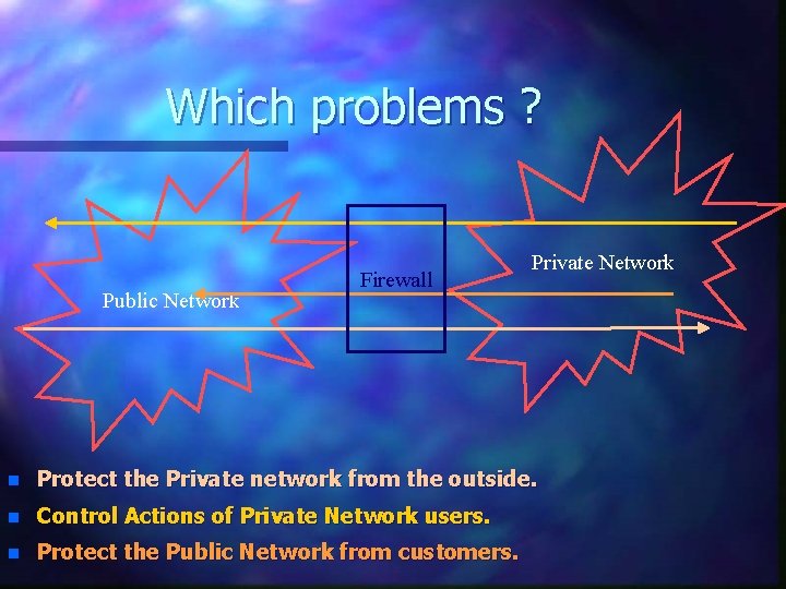
Which problems ? Public Network Firewall Private Network n Protect the Private network from the outside. n Control Actions of Private Network users. n Protect the Public Network from customers.
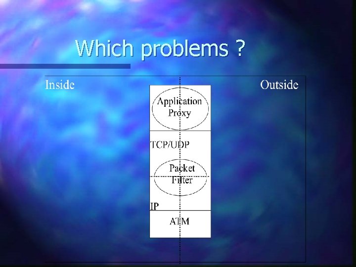
Which problems ?
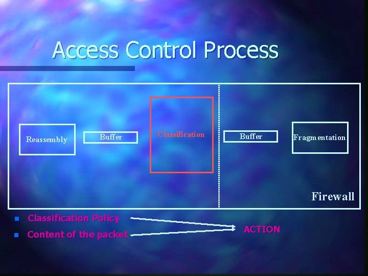
Access Control Process Reassembly Buffer Classification Buffer Fragmentation Firewall n Classification Policy n Content of the packet ACTION
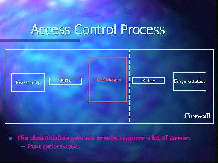
Access Control Process Reassembly Buffer Classification Buffer Fragmentation Firewall n The classification process usually requires a lot of power. – Poor performance.
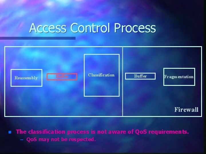
Access Control Process Reassembly Buffer Classification Buffer Fragmentation Firewall n The classification process is not aware of Qo. S requirements. – Qo. S may not be respected.
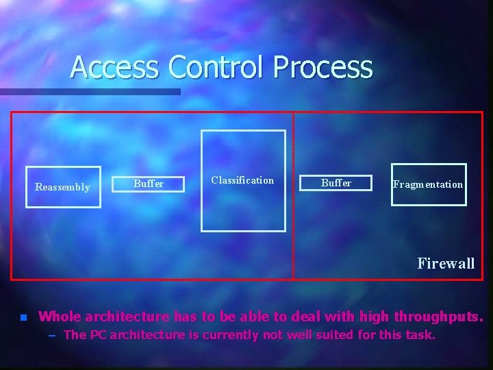
Access Control Process Reassembly Buffer Classification Buffer Fragmentation Firewall n Whole architecture has to be able to deal with high throughputs. – The PC architecture is currently not well suited for this task.
CARAT - Goals Security level similar to a stateless packet filter. n Improving access control on ATM Signalling. n High speed. n – Worst case throughput = 620 Mb/s. n Qo. S preservation. – Delay has to be small and bounded. n Easy to manage.
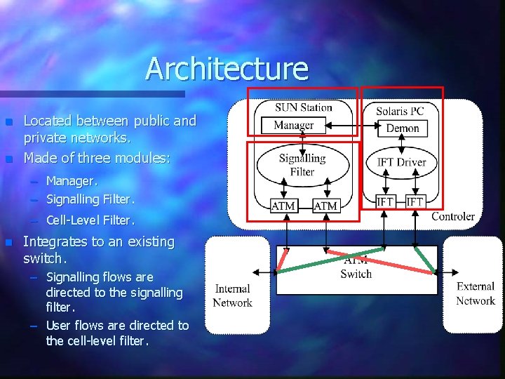
Architecture n n Located between public and private networks. Made of three modules: – Manager. – Signalling Filter. – Cell-Level Filter. n Integrates to an existing switch. – Signalling flows are directed to the signalling filter. – User flows are directed to the cell-level filter.
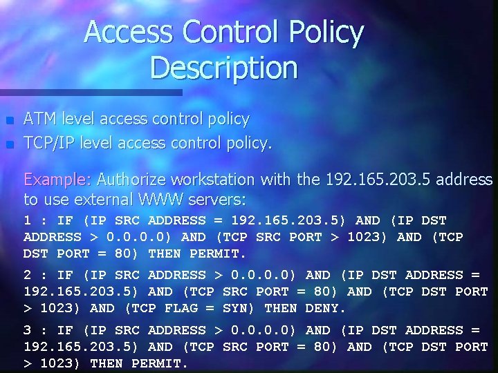
Access Control Policy Description n n ATM level access control policy TCP/IP level access control policy. Example: Authorize workstation with the 192. 165. 203. 5 address to use external WWW servers: 1 : IF (IP SRC ADDRESS = 192. 165. 203. 5) AND (IP DST ADDRESS > 0. 0) AND (TCP SRC PORT > 1023) AND (TCP DST PORT = 80) THEN PERMIT. 2 : IF (IP SRC ADDRESS > 0. 0) AND (IP DST ADDRESS = 192. 165. 203. 5) AND (TCP SRC PORT = 80) AND (TCP DST PORT > 1023) AND (TCP FLAG = SYN) THEN DENY. 3 : IF (IP SRC ADDRESS > 0. 0) AND (IP DST ADDRESS = 192. 165. 203. 5) AND (TCP SRC PORT = 80) AND (TCP DST PORT > 1023) THEN PERMIT.
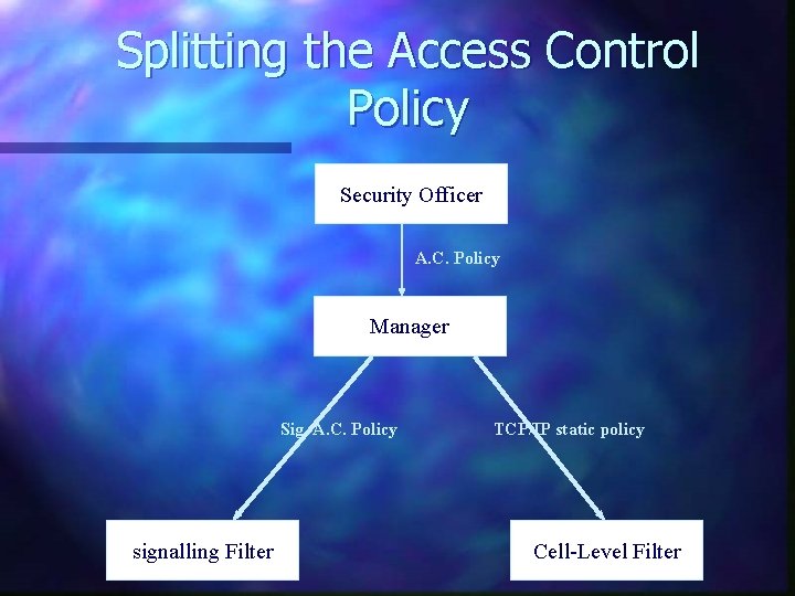
Splitting the Access Control Policy Security Officer A. C. Policy Manager Sig. A. C. Policy signalling Filter TCP/IP static policy Cell-Level Filter
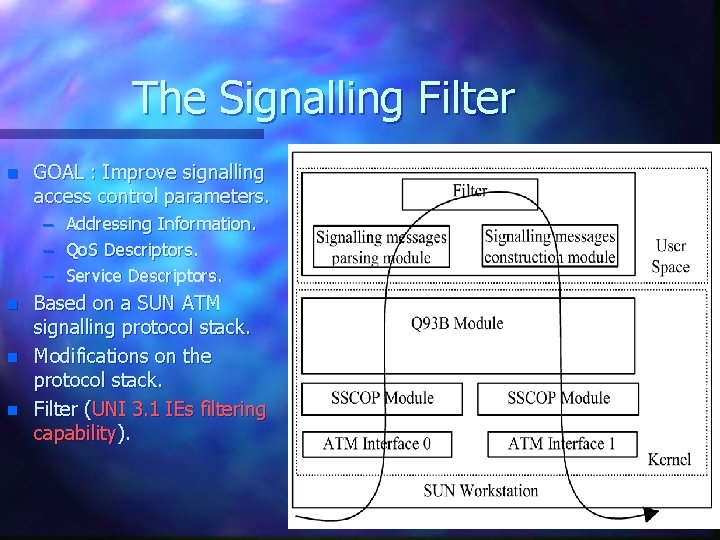
The Signalling Filter n GOAL : Improve signalling access control parameters. – – – n n n Addressing Information. Qo. S Descriptors. Service Descriptors. Based on a SUN ATM signalling protocol stack. Modifications on the protocol stack. Filter (UNI 3. 1 IEs filtering capability).
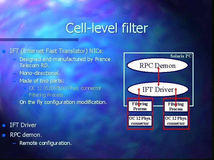
Cell-level filter n IFT (Internet Fast Translator) NICs: – Designed and manufactured by France Telecom RD. – Mono-directional. – Made of two parts: n n OC 12 (620 Mb/s) Phys. connector. Filtering Process. – On the fly configuration modification. n IFT Driver n RPC demon. – Remote configuration. Solaris PC RPC Demon IFT Driver Filtering Process OC 12 Phys. connector
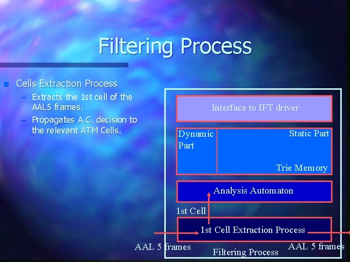
Filtering Process n Cells Extraction Process – Extracts the 1 st cell of the AAL 5 frames. – Propagates A. C. decision to the relevant ATM Cells. Interface to IFT driver Static Part Dynamic Part Trie Memory Analysis Automaton 1 st Cell Extraction Process AAL 5 frames Filtering Process AAL 5 frames
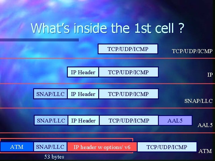
What’s inside the 1 st cell ? SNAP/LLC TCP/UDP/ICMP IP Header TCP/UDP/ICMP IP IP Header TCP/UDP/ICMP SNAP/LLC ATM SNAP/LLC IP Header SNAP/LLC IPIPHeader TCP/UDP/ICMP header w options/ v 6 TCP/UDP/ICMP 53 bytes TCP/UDP/ICMP AAL 5 ATM
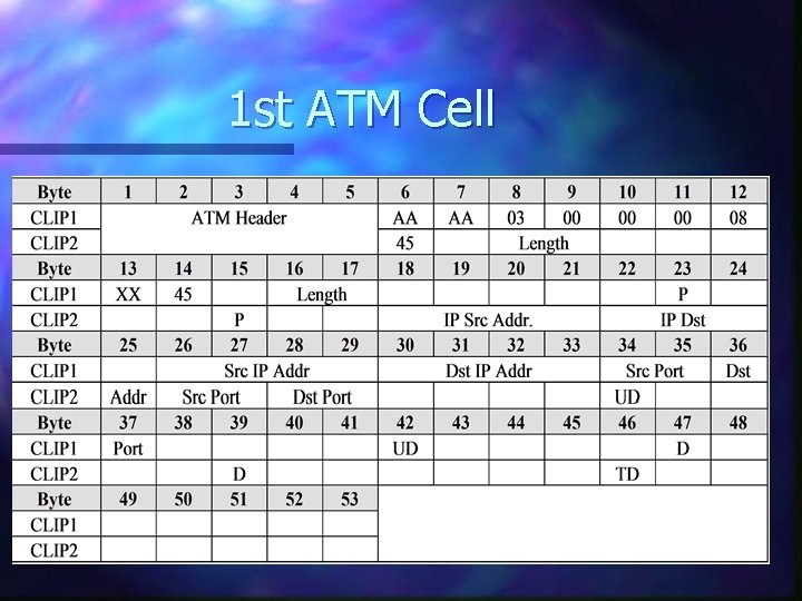
1 st ATM Cell
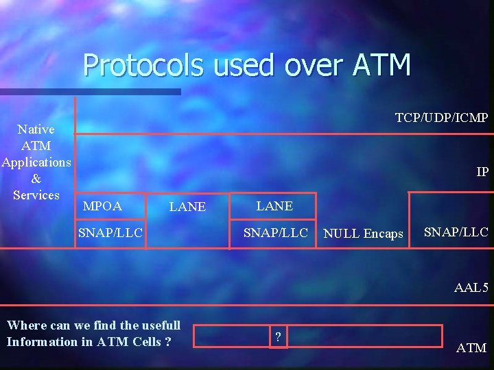
Protocols used over ATM Native ATM Applications & Services TCP/UDP/ICMP IP MPOA LANE SNAP/LLC NULL Encaps SNAP/LLC AAL 5 Where can we find the usefull Information in ATM Cells ? ? ATM
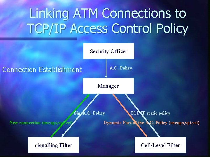
Linking ATM Connections to TCP/IP Access Control Policy Security Officer Connection Establishment A. C. Policy Manager Sig. A. C. Policy New connection (encaps, vpi, vci) signalling Filter TCP/IP static policy Dynamic Part of the A. C. Policy (encaps, vpi, vci) Cell-Level Filter
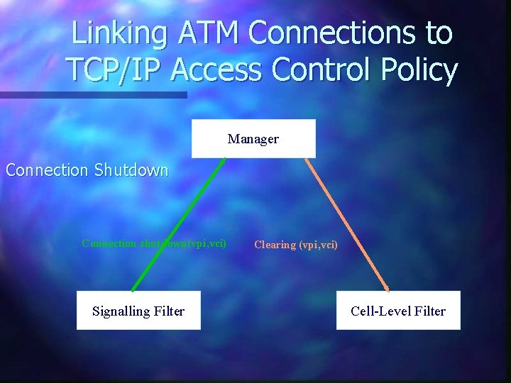
Linking ATM Connections to TCP/IP Access Control Policy Manager Connection Shutdown Connection shutdown(vpi, vci) Signalling Filter Clearing (vpi, vci) Cell-Level Filter
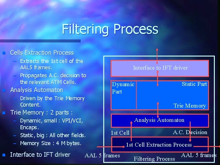
Filtering Process n Cells Extraction Process – Extracts the 1 st cell of the AAL 5 frames. – Propagates A. C. decision to the relevant ATM Cells. n Analysis Automaton – Driven by the Trie Memory Content. n Interface to IFT driver Static Part Dynamic Part Trie Memory : 2 parts : – Dynamic, small : VPI/VCI, Encaps. – Static, big : All other fields. – Memory Size : 4 M bytes. n Interface to IFT driver Analysis Automaton 1 st Cell AAL 5 frames A. C. Decision 1 st Cell Extraction Process Filtering Process AAL 5 frames
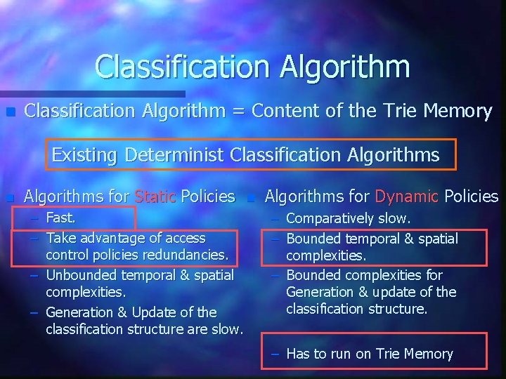
Classification Algorithm n Classification Algorithm = Content of the Trie Memory Existing Determinist Classification Algorithms for Static Policies – Fast. – Take advantage of access control policies redundancies. – Unbounded temporal & spatial complexities. – Generation & Update of the classification structure are slow. n Algorithms for Dynamic Policies – Comparatively slow. – Bounded temporal & spatial complexities. – Bounded complexities for Generation & update of the classification structure. – Has to run on Trie Memory
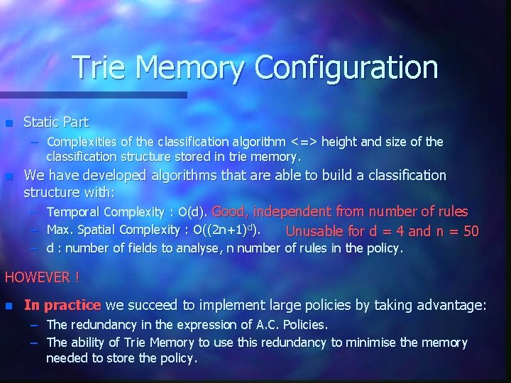
Trie Memory Configuration n Static Part – Complexities of the classification algorithm <=> height and size of the classification structure stored in trie memory. n We have developed algorithms that are able to build a classification structure with: – Temporal Complexity : O(d). Good, independent from number of rules – Max. Spatial Complexity : O((2 n+1)d). Unusable for d = 4 and n = 50 – d : number of fields to analyse, n number of rules in the policy. HOWEVER ! n In practice we succeed to implement large policies by taking advantage: – The redundancy in the expression of A. C. Policies. – The ability of Trie Memory to use this redundancy to minimise the memory needed to store the policy.
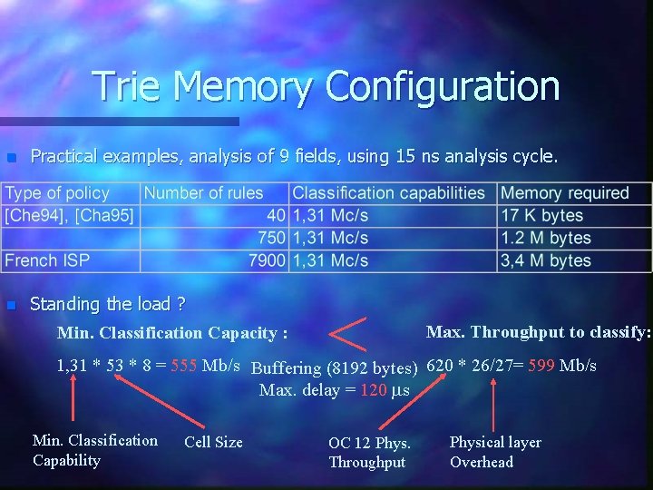
Trie Memory Configuration n Practical examples, analysis of 9 fields, using 15 ns analysis cycle. n Standing the load ? Min. Classification Capacity : < Max. Throughput to classify: 1, 31 * 53 * 8 = 555 Mb/s Buffering (8192 bytes) 620 * 26/27= 599 Mb/s Max. delay = 120 s Min. Classification Capability Cell Size OC 12 Phys. Throughput Physical layer Overhead
Conclusion n Security – Similar to a stateless packet filter. n Good performance – High Speed (577 Mb/s) and small delay (<120 s) – Throughput and delay don’t depend on policy and packets sizes. n Improved ATM signalling access control. – Almost all the information provided by signalling IEs can be used. n Easy to manage – Single access control policy definition language. n However some problems remain to be solved: – IP options problem and IPv 6.
Future n Possible evolutions for our prototype – – – n Tests in real networks. Translators for popular router filtering languages. Classification algorithms improvements. Possible evolutions for the IFTs – – IP Version (Without ATM support). New physical connector (1 Gb/s). In deep analysis (255 bytes). New tools to improve classification algorithms. n QUESTION : Can we still take advantage of rules redundancy with application level policies ?
- Slides: 26