A Diesel cycle The ideal cycle for CI

 (1) Temperature rise")


- Slides: 20
A. Diesel cycle : The ideal cycle for CI engines • An CI power cycle useful in many forms of automotive transportation, railroad engines, and ship power plants • Replace (the spark plug + carburetor) in SI by fuel injector in CI engines. Spark plug Air-fuel mixture Gasoline engine Fuel injector Fuel spray Diesel engine
A. Diesel cycle : The ideal cycle for CI engines (2) (1) Temperature rise about the autoignition temperature of the fuel. Inlet valve open and fresh air is drawn into the cylinder (3) Intake compression Evaporation, mixing, ignition and combustion of diesel fuel. In the later stages, expansion process occur. Diesel fuel is sprayed into the combustion chamber. (4) Burned gases is pushed out to the exhaust valve Combustion Exhaust
A Diesel cycle : The ideal cycle for CI engines Processes: 1 -2 Compression (s = Const) 2 -3 Combustion (P = Const. ) 3 -4 Expansion (s = Const) 4 -1 Exhaust (V = Const) T P 2 3 3 Is ex en pa tro ns pic io n co Ise m ntr pr op es ic si on (a) P-v diagram t nstan P=co 2 4 4 nt 1 1 v ta ns co v= (b) T-s diagram • Eliminates pre-ignition of the fuel-air mixture when compression ratio is high. • The combustion process in CI engines takes place over a longer interval and is approximated as constantpressure heat addition process. s
2. 6 Diesel cycle : The ideal cycle for CI engines • Energy balance for closed system: p = Constant 2 qin qout 1 3 4 V = Constant s
A. Diesel cycle : The ideal cycle for CI engines • Define a new quantity
A. Diesel cycle : The ideal cycle for CI engines • As the cut off ratio decreases, increases • The diesel engines operate at much higher r and usually more efficient than spark-ignition engines. • The diesel engines also burn the fuel more completely since they usually operate at lower rpm than SI engines. • CI engines operate on lower fuel costs.
A. Diesel cycle : The ideal cycle for CI engines • At rc = 1, the Diesel and Otto cycles have the same efficiency. • Physical implication for the Diesel cycle: No change in volume when heat is supplied. • A high value of k compensates for this. • For rc > 1, the Diesel cycle is less efficient than the Otto cycle.
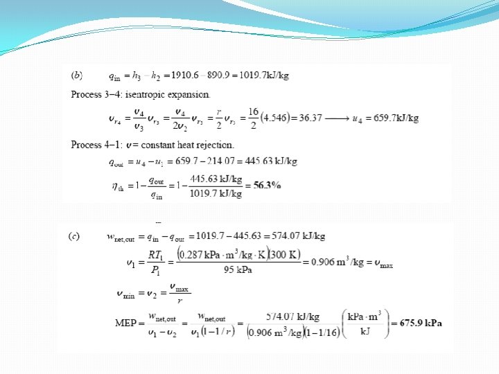
Example An air standard Diesel cycle has a compression ratio of 16 and cut off ratio of 2. At beginning of the compression process, air is at 95 k. Pa and 27 o. C. Accounting for the variation of specific heat with temperature, determine a) Temperature after the heat additional process. b) Thermal efficiency c) The mean effective pressure Solution :
Solution :
Dual cycle: A more realistic ideal cycle model for modern, high-speed compression ignition engine. P-v diagram of an ideal dual cycle.
A. Diesel cycle : The ideal cycle for CI engines The ideal Dual cycle • The dual cycle is designed to capture some of the advantages of both the Otto and Diesel cycles. • It it is a better approximation to the actual operation of the compression ignition engine.
A. Diesel cycle : The ideal cycle for CI engines The ideal Dual cycle p 3 qin, V` qin, P 4 s = Constant 2 5 1 qout, V
A. Diesel cycle : The ideal cycle for CI engines The ideal Dual cycle 3 qin, P 4 qin, V 2 5 1 qout, P V
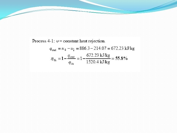
Example 9 -54 The compression cycle of an ideal dual cycle is 14. Air is at 100 k. Pa and 300 K at beginning of the compression process and at 2, 200 K at the end of heat addition process. Heat transfer process to air is take place partly at constant volume and partly at constant pressure and its amount to 1, 520. 4 k. J/kg. Assume variable specific heat for air, determine thermal efficiency of the cycle.
Solution 9 -54
Example: An ideal Diesel engine has a diameter of 15 cm and stroke 20 cm. The clearance volume is 10 percent of swept volume. Determine the compression ratio and the air standard efficiently of engine if the cut off takes place at 6 percent of the stroke. Solution: Given that: Swept volume Vs = π/4 d 2. L = π/4 (15)2 X 20 = 3540 cm 3 Clearance volume Vc = 0. 1 Vs = 354 cm 3 Total volume V 1 = Vc + Vs = (354 + 3540) cm 3 ⇒ V 1 = 3894 cm 3 Compression ratio, r = V 1/V 2 = V 1/Vc = 3894 / 354 = 11 Cut off ratio; ß = V 3 / V 2 = V 2 + (V 3 – V 2) / V 2 = 354 + 3540 X 0. 06 / 354 = 1. 6 Air standard efficiency of the cycle: ∏diesel = 1 – 1/r∏– 1 [ß∏– 1 / ∏(ß– 1)] = 1 – 1/(11)0. 4 [(1. 6)1. 4 – 1 / 1. 4 (1. 6 – 1)] = 0. 5753 (or 57. 53 percent)
Example: A diesel engine receives air at 0. 1 MPa and 300 o K in the beginning of compression stroke. The compression ratio is 16. Heat added per kg of air is 1506 k. J/kg. Determine fuel cut off ratio and cycle thermal efficiency. Assume Cp = 1. 0 k. J / kg K, R = 0. 286 k. J/kg K Solution: For process (1 -2) T 2 / T 1 = r∏– 1 ∏ = Cp / Cv = 1. 0 / 0. 714 = 1. 4 (Cv = Cp – R = 1. 0 – 0. 286 = 0. 714 k. J/kg K) T 2 = T 1. (16)1. 4– 1 = 300 (16)(1. 4– 1) = 909. 43 K For Process (2 -3) T 3 / T 2 = v 3 / v 2 = ∏ Heat added = Cp (T 3 – T 2) 1500 = 1 (T 3 – 909. 43) ⇒ T 3 = 2409. 43 K ∴ T 3 / T 2 = 2409. 43 / 909. 43 = 2. 65 Fuel cut off ratio, ∏ = T 3 / T 2 = 2. 65 ∴ ∏cycle = 1 – 1/r∏– 1 [∏∏– 1 / ∏ (∏– 1)] = 1 – 1 / 160. 4 (2. 651. 4 – 1 / 1. 4(2. 65 – 1)) = 1 – 0. 32987 (1. 26117) = 0. 5839 = 58. 39%