
A Detector for the ILC Ties Behnke DESY
A Detector for the ILC Ties Behnke, DESY
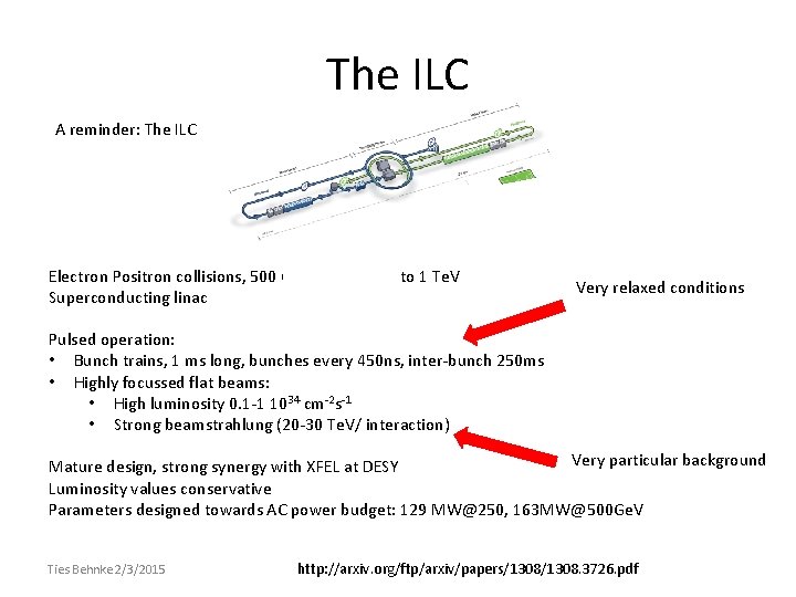
The ILC A reminder: The ILC Electron Positron collisions, 500 Ge. V upgradable to 1 Te. V Superconducting linac Very relaxed conditions Pulsed operation: • Bunch trains, 1 ms long, bunches every 450 ns, inter-bunch 250 ms • Highly focussed flat beams: • High luminosity 0. 1 -1 1034 cm-2 s-1 • Strong beamstrahlung (20 -30 Te. V/ interaction) Very particular background Mature design, strong synergy with XFEL at DESY Luminosity values conservative Parameters designed towards AC power budget: 129 MW@250, 163 MW@500 Ge. V Ties Behnke 2/3/2015 http: //arxiv. org/ftp/arxiv/papers/1308. 3726. pdf
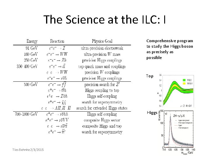
The Science at the ILC: I Comprehensive program to study the Higgs boson as precisely as possible Top Higgs Ties Behnke 2/3/2015
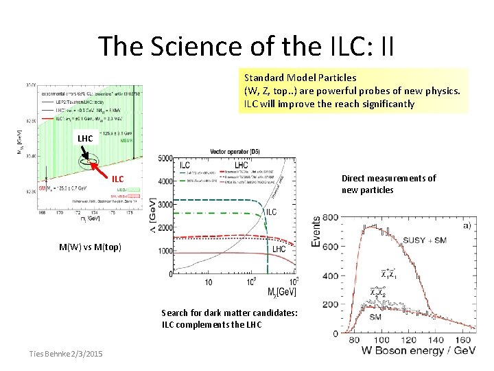
The Science of the ILC: II Standard Model Particles (W, Z, top. . ) are powerful probes of new physics. ILC will improve the reach significantly LHC Direct measurements of new particles ILC M(W) vs M(top) Search for dark matter candidates: ILC complements the LHC Ties Behnke 2/3/2015
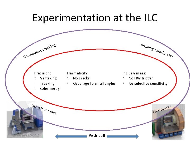
Experimentation at the ILC Ima g ous u n i nt kin trac ging Co Precision: • Vertexing • Tracking • calorimetry Ultra Ties Behnke 2/3/2015 low- mas Hermeticity: • No cracks • Coverage to small angles calo r Push-pull er Inclusiveness: • No HW trigger • No selective sensitivity Low s ime t r e pow
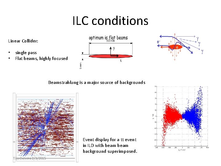
ILC conditions Linear Collider: • • single pass Flat beams, highly focused Beamstrahlung is a major source of backgrounds Event display for a tt event in ILD with beam background superimposed. Ties Behnke 2/3/2015
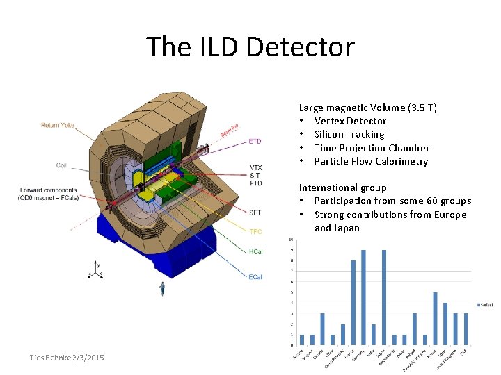
The ILD Detector Large magnetic Volume (3. 5 T) • Vertex Detector • Silicon Tracking • Time Projection Chamber • Particle Flow Calorimetry International group • Participation from some 60 groups • Strong contributions from Europe and Japan Ties Behnke 2/3/2015
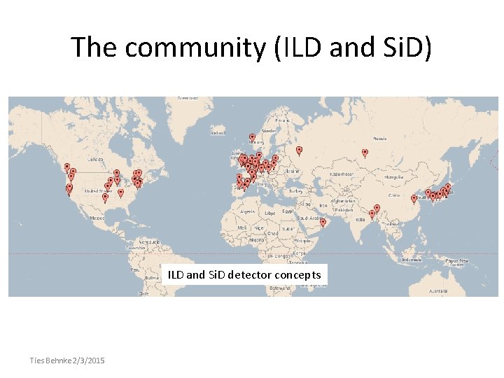
The community (ILD and Si. D) ILD and Si. D detector concepts Ties Behnke 2/3/2015
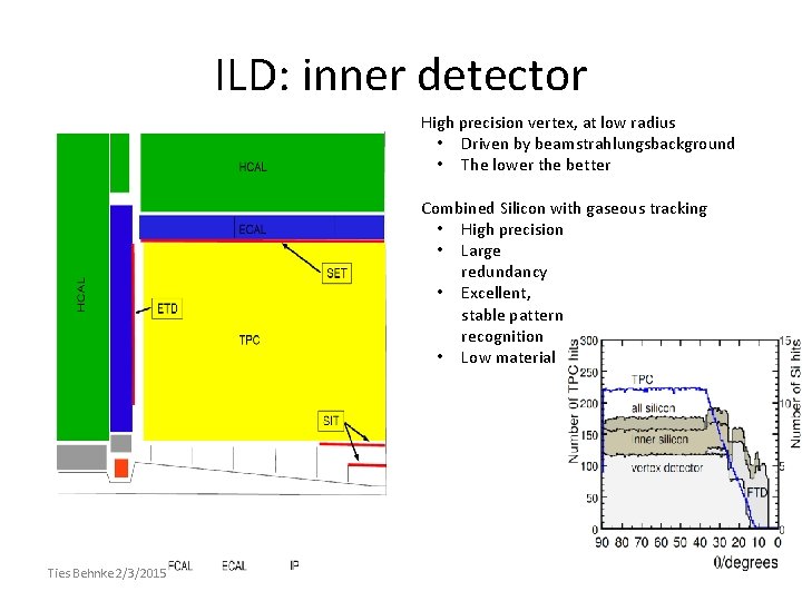
ILD: inner detector Ties Behnke 2/3/2015 • High precision vertex, at low radius • Driven by beamstrahlungsbackground • The lower the better • Combined Silicon with gaseous tracking • High precision • Large redundancy • Excellent, stable pattern recognition • Low material
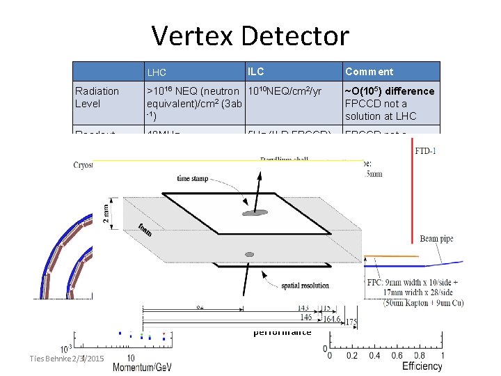
Vertex Detector ILC LHC Radiation Level >1016 NEQ (neutron 1010 NEQ/cm 2/yr equivalent)/cm 2 (3 ab -1) Readout 40 MHz speed requirement (time structure of beam) Hit density 2. 4 hits/cm 2/bunch (r=8 cm) 12. 5 ns ~O(105) difference FPCCD not a solution at LHC 5 Hz (ILD FPCCD) 100 k. Hz (ILD CMOS) 3 MHz (Si. D) FPCCD not a solution at LHC ~6 hits/cm 2/bunch (r=1. 6 cm) 300 ns Factor of ~3 difference for a given pixel size IP resolution vs. momentum Flavour tag performance Ties Behnke 2/3/2015 Comment
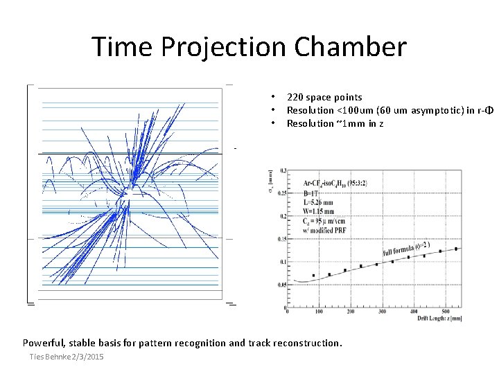
Time Projection Chamber • • • 220 space points Resolution <100 um (60 um asymptotic) in r-Φ Resolution ~1 mm in z Powerful, stable basis for pattern recognition and track reconstruction. Ties Behnke 2/3/2015
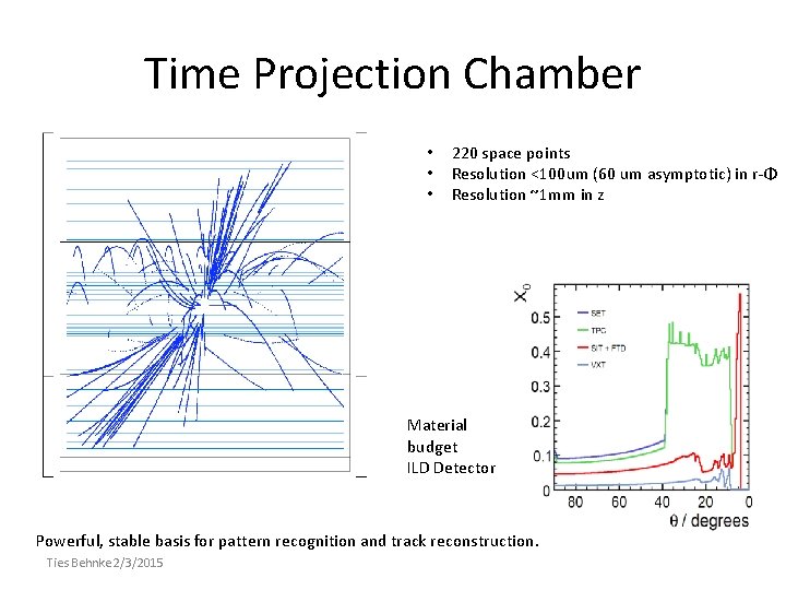
Time Projection Chamber • • • 220 space points Resolution <100 um (60 um asymptotic) in r-Φ Resolution ~1 mm in z Material budget ILD Detector Powerful, stable basis for pattern recognition and track reconstruction. Ties Behnke 2/3/2015
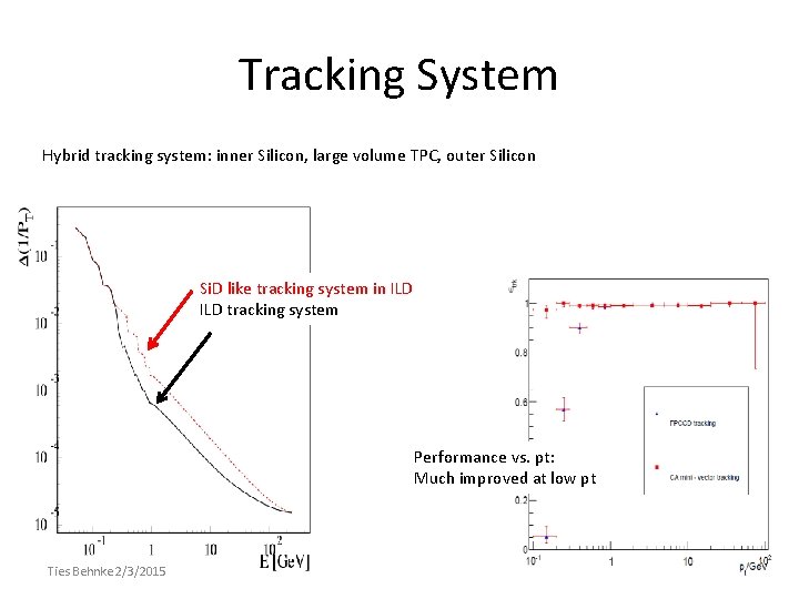
Tracking System Hybrid tracking system: inner Silicon, large volume TPC, outer Silicon Si. D like tracking system in ILD tracking system Performance vs. pt: Much improved at low pt Ties Behnke 2/3/2015
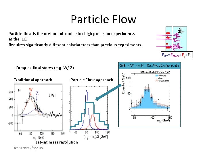
Particle Flow Particle flow is the method of choice for high precision experiments at the ILC. Requires significantly different calorimeters than previous experiments. Complex final states (e. g. W/ Z) Traditional approach Particle Flow approach Jet-jet mass resolution Ties Behnke 2/3/2015
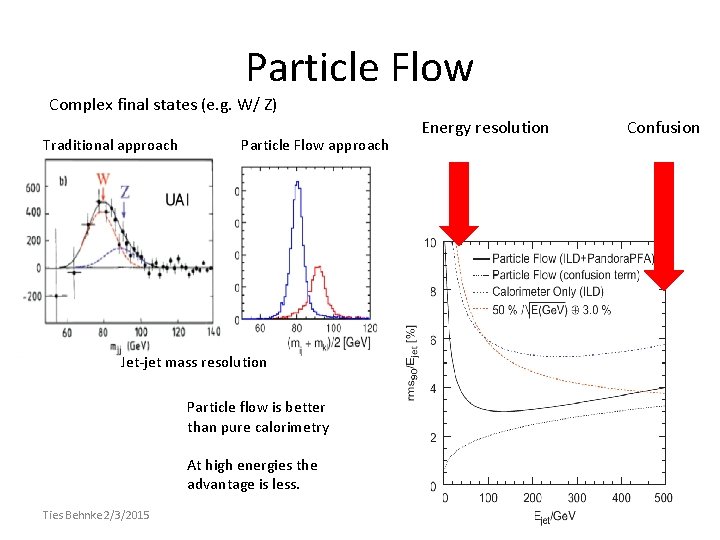
Particle Flow Complex final states (e. g. W/ Z) Traditional approach Particle Flow approach Jet-jet mass resolution Particle flow is better than pure calorimetry At high energies the advantage is less. Ties Behnke 2/3/2015 Energy resolution Confusion
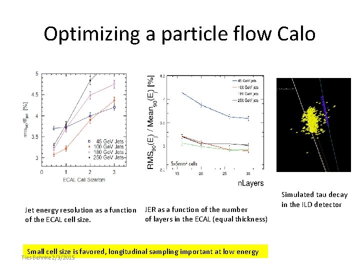
Optimizing a particle flow Calo Jet energy resolution as a function of the ECAL cell size. JER as a function of the number of layers in the ECAL (equal thickness) Small cell size is favored, longitudinal sampling important at low energy Ties Behnke 2/3/2015 Simulated tau decay in the ILD detector
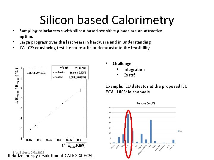
Silicon based Calorimetry • • • Sampling calorimeters with silicon based sensitive planes are an attractive option. Large progress over the last years in hardware and in understanding CALICE: convincing test beam results to demonstrate the feasibility • Challenge: • Integration • Costs! Example: ILD detector at the proposed ILC ECAL 100 Mio channels Ties Behnke 2/3/2015 Relative energy resolution of CALICE SI-ECAL
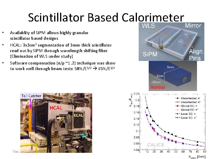
Scintillator Based Calorimeter • • • Availablity of Si. PM allows highly granular scintillator based designs HCAL: 3 x 3 cm 2 segmentation of 3 mm thick scintillator read out by Si. PM through wavelength shifting fiber (Elimination of WLS under study) Software compensation (e/p ~1. 2) technique was show to work well through beam tests: 58%/E 1/2 45%/E 1/2 Ties Behnke 2/3/2015
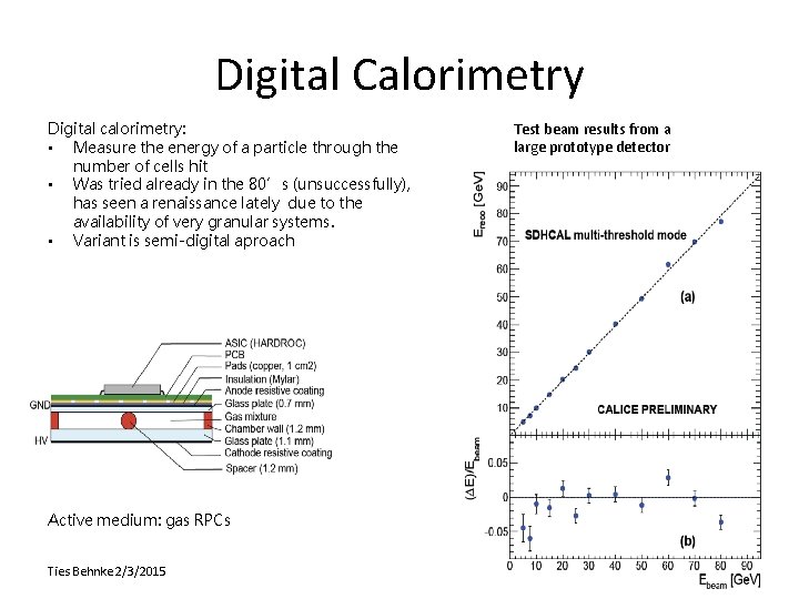
Digital Calorimetry Digital calorimetry: • Measure the energy of a particle through the number of cells hit • Was tried already in the 80’s (unsuccessfully), has seen a renaissance lately due to the availability of very granular systems. • Variant is semi-digital aproach Active medium: gas RPCs Ties Behnke 2/3/2015 Test beam results from a large prototype detector
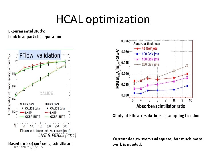
HCAL optimization Experimental study: Look into particle separation Study of Pflow resolutions vs sampling fraction Based on 3 x 3 cm 2 cells, scintillator Ties Behnke 2/3/2015 Current design seems adequate, but much more work is needed.
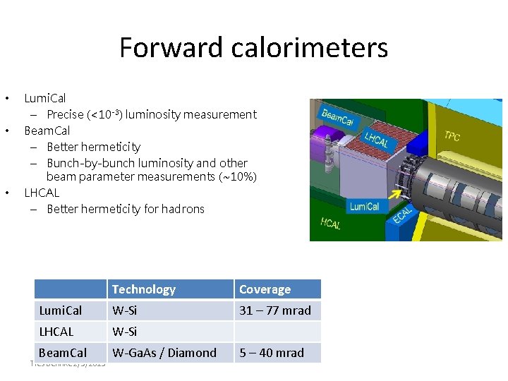
Forward calorimeters • • • Lumi. Cal – Precise (<10 -3) luminosity measurement Beam. Cal – Better hermeticity – Bunch-by-bunch luminosity and other beam parameter measurements (~10%) LHCAL – Better hermeticity for hadrons Technology Coverage Lumi. Cal W-Si 31 – 77 mrad LHCAL W-Si Beam. Cal W-Ga. As / Diamond Ties Behnke 2/3/2015 5 – 40 mrad
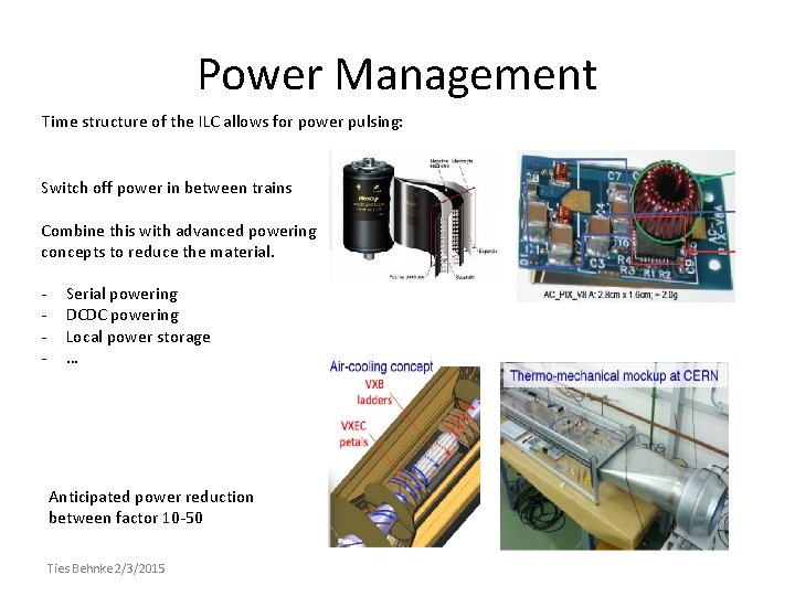
Power Management Time structure of the ILC allows for power pulsing: Switch off power in between trains Combine this with advanced powering concepts to reduce the material. - Serial powering DCDC powering Local power storage … Anticipated power reduction between factor 10 -50 Ties Behnke 2/3/2015
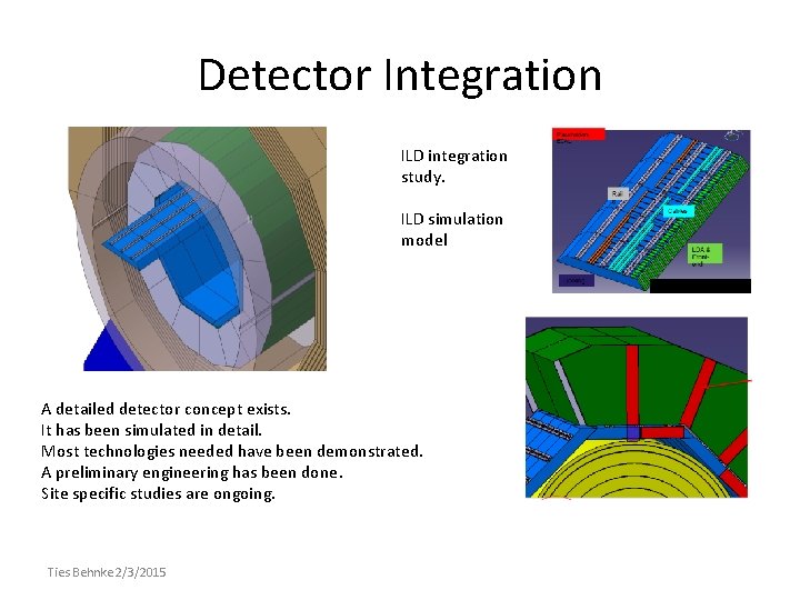
Detector Integration ILD integration study. ILD simulation model A detailed detector concept exists. It has been simulated in detail. Most technologies needed have been demonstrated. A preliminary engineering has been done. Site specific studies are ongoing. Ties Behnke 2/3/2015
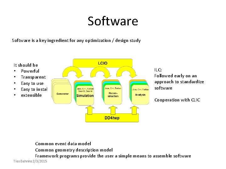
Software is a key ingredient for any optimization / design study It should be • Powerful • Transparent • Easy to use • Easy to install • extensible ILC: Followed early on an approach to standardize software Cooperation with CLIC Common event data model Common geometry description model Framework programs provide the user a simple means to assemble software Ties Behnke 2/3/2015
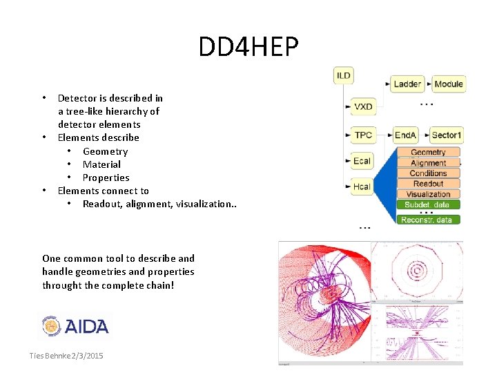
DD 4 HEP • • • Detector is described in a tree-like hierarchy of detector elements Elements describe • Geometry • Material • Properties Elements connect to • Readout, alignment, visualization. . One common tool to describe and handle geometries and properties throught the complete chain! Ties Behnke 2/3/2015
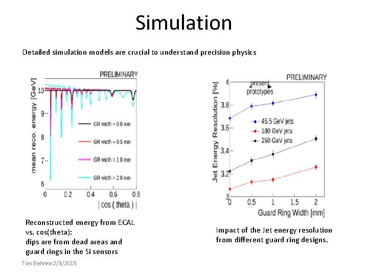
Simulation Detailed simulation models are crucial to understand precision physics Reconstructed energy from ECAL vs. cos(theta): dips are from dead areas and guard rings in the Si sensors Ties Behnke 2/3/2015 Impact of the Jet energy resolution from different guard ring designs.
Structures ILD concept group: • Fairly loose organisation • Slowly moving towards a more formal “club”, but still far from a collaboration R&D collaborations • Technical questions are mostly addressed by R&D collaborations (CALICE, LCTPC, …) • Have their own structures • Get their own funding • Powerful tool to leverage R&D funds from different sources Cooperation • Tried to maintain common basis with other groups (concepts, general studies …) • Common tools played an important role in this. Ties Behnke 2/3/2015
Summary Detector studies have been ongoing at the ILC for some time Integrated detector concepts have been developed • • • Fairly detailed designs exist Most key technologies are beyond “proof of principle” Detailed models of the detector exist Close cooperation between R&D groups and detector concept group is essential Next step: much more detailed engineering needed, full integration model is needed, site specific studies are needed. Ties Behnke 2/3/2015
- Slides: 28