
A Course on Hydropower Engineering SEE 7092 By

A Course on “ Hydropower Engineering (SEE 7092)” By: Dr. Tilahun Nigussie Assistant Professor in Thermal and Energy Systems Engineering: Addis Ababa Institute of Technology, Addis Ababa University Course Break down
Hydropower Engineering (SEE 7069) Chapter one Introduction to Hydropower
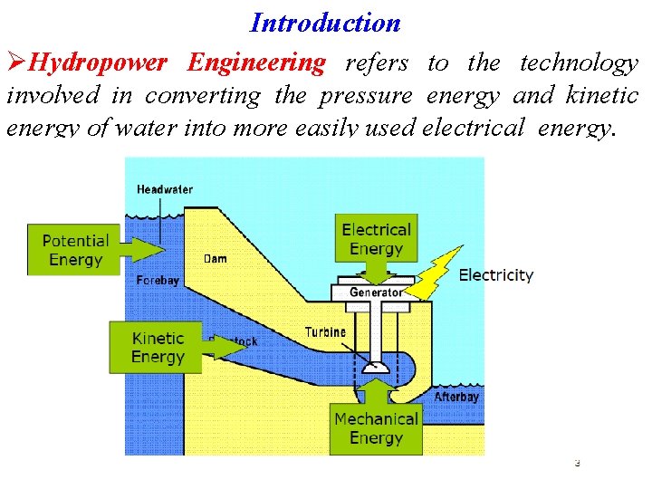
Introduction ØHydropower Engineering refers to the technology involved in converting the pressure energy and kinetic energy of water into more easily used electrical energy.
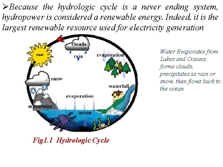
ØBecause the hydrologic cycle is a never ending system, hydropower is considered a renewable energy. Indeed, it is the largest renewable resource used for electricity generation Water Evaporates from Lakes and Oceans, forms clouds, precipitates as rain or snow, then flows back to the ocean Fig 1. 1 Hydrologic Cycle
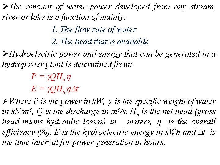
ØThe amount of water power developed from any stream, river or lake is a function of mainly: 1. The flow rate of water 2. The head that is available ØHydroelectric power and energy that can be generated in a hydropower plant is determined from: P = QHn E = QHn t ØWhere P is the power in k. W, is the specific weight of water in k. N/m 3, Q is the discharge in m 3/s, Hn is the net head (gross head minus hydraulic losses) in meters, is the overall efficiency (%), E is the hydroelectric energy in k. Wh and t is the time interval for power generation in hours.
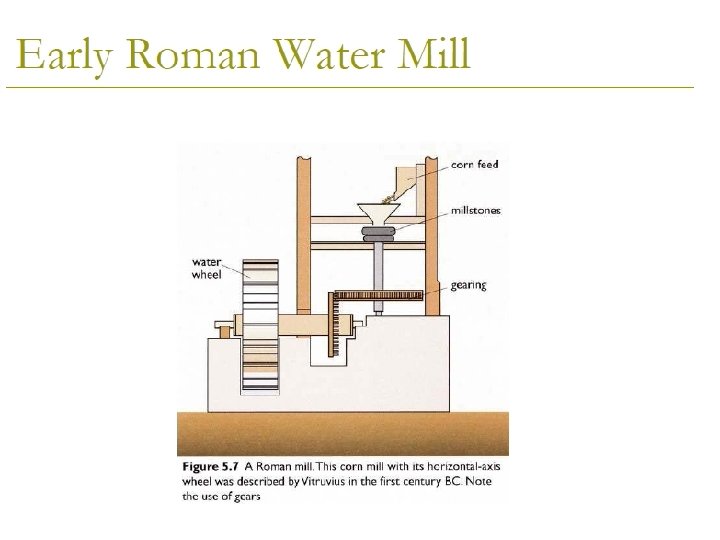
History of Hydropower ØEarlier in the history of energy development and use, water wheels provided power by direct connection or with pulley and gear systems to drive various machines, such as grist mills and textile mills. ØSince ancient times, water wheels have been used for lifting water from a lower to a higher elevation in irrigation systems. ØThe ancient Greeks invented the water wheel and were, along with the Romans, the first to use it in nearly all of the forms and functions. ØThe modern turbine has been developed as a result of the improvements of the waterwheel. Most of the developments were achieved by French engineers.
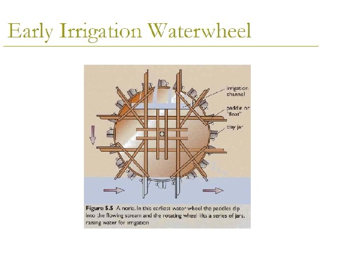
Water Wheels • Types of water wheels are based upon where the water strikes it – Pitchback – water drops from top and is deflected backwards to fall back towards the dam/river – Overshot – shoots over the top onto the wheel; the usual kind – Breastshot – strikes about 50% to 80% of height of the near side of the wheel – Undershot – pushes underneath and need not be more than immersed in a stream • Waterwheels turn slowly compared with turbines – one to fifty rpm 10
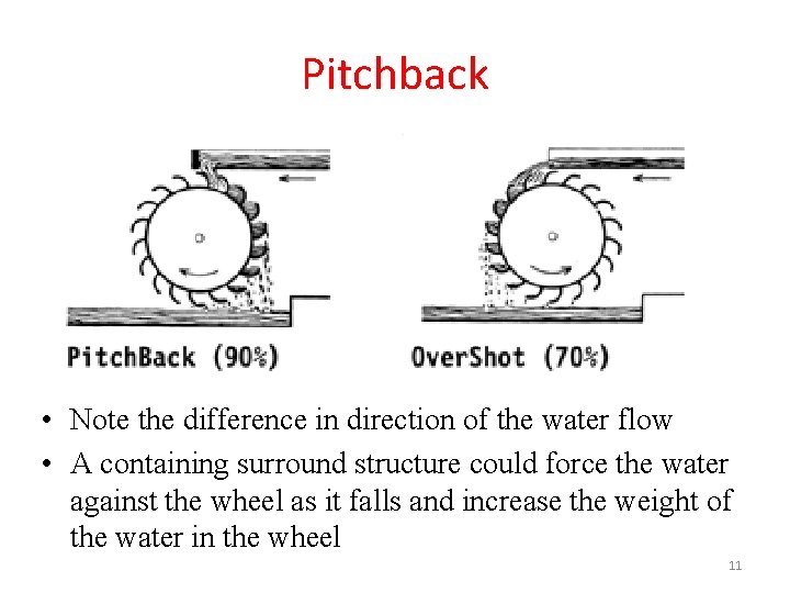
Pitchback • Note the difference in direction of the water flow • A containing surround structure could force the water against the wheel as it falls and increase the weight of the water in the wheel 11
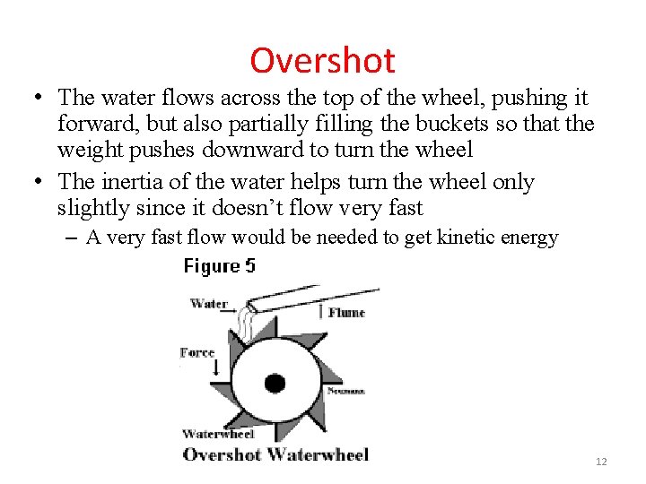
Overshot • The water flows across the top of the wheel, pushing it forward, but also partially filling the buckets so that the weight pushes downward to turn the wheel • The inertia of the water helps turn the wheel only slightly since it doesn’t flow very fast – A very fast flow would be needed to get kinetic energy 12
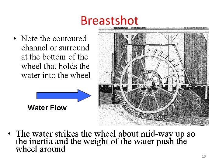
Breastshot • Note the contoured channel or surround at the bottom of the wheel that holds the water into the wheel Water Flow • The water strikes the wheel about mid-way up so the inertia and the weight of the water push the wheel around 13
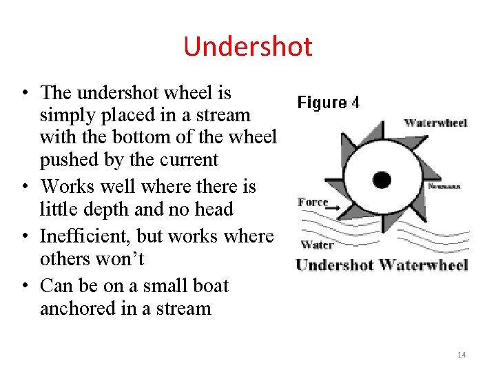
Undershot • The undershot wheel is simply placed in a stream with the bottom of the wheel pushed by the current • Works well where there is little depth and no head • Inefficient, but works where others won’t • Can be on a small boat anchored in a stream 14
ØIn 1849, the Francis turbine was invented and later used in world’s first hydroelectric power plant. ØAlternating current is used today. That breakthrough came when the electric generator was coupled to the turbine, which resulted in the worlds, and the United States', first hydroelectric plant located in Appleton, Wisconsin, in 1882. ØPresent-day hydroelectric plant is the end-product of 2000 years of technological advance, from the creaking wooden wheel, converting a few percent of water power into useful mechanical output, to the modern turbo-generator spinning at 1500 revolutions per minute and producing electric power at efficiencies which can reach 90 %.
ØThe existing development of hydropower has resulted from a fairly uniform rate of increase in competition with other modes of electrical energy production. ØUntil the mid-1970 s, the pattern of hydro development was to develop bigger and bigger units because smaller hydro plants were not competitive with fossil fuel power plants. ØDuring the period from 1940 to 1970, small units were actually forced out of production because of the high cost of operation and the ready availability of electrical energy from large steam power plants and large high-capacity hydro plants. ØRecently, with rising costs of fossil fuels, the economic feasibility of small-scale hydro has changed making it an attractive energy production alternative.
Terminology and Turbine Types Terminology Ø Power capacity is often used in referring to the rated capability of the hydro plant to produce energy. Manufacturers of hydraulic turbines are usually required to specify what the rated capacity of their units is in either horsepower or kilowatts. Ø Demand Load • Demand refers' to the amount of power needed or desired; • load refers to the rate at which electrical energy is actually delivered to or by a system. In this context, load can include the output from several hydropower plants.
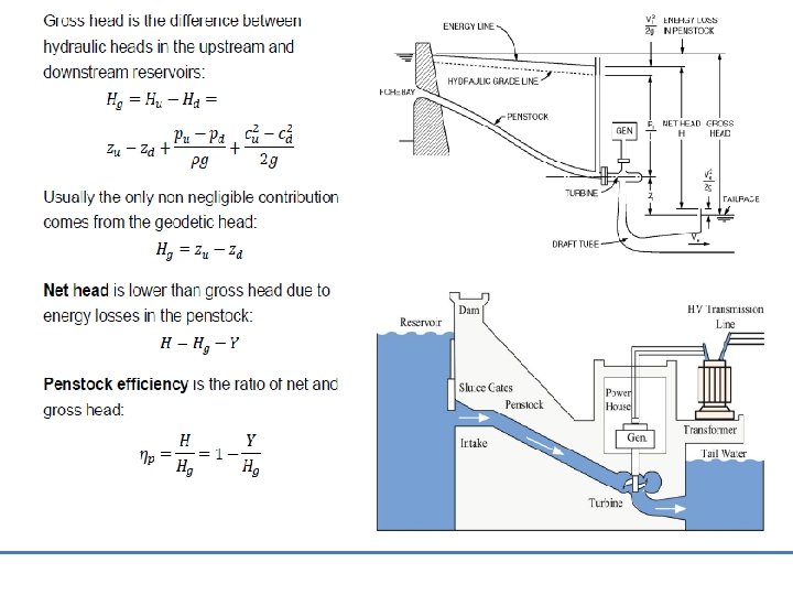
Ø Full gate Discharge : is the flow condition which prevails when turbine gates or valves are fully open. At maximum rated head and full gate, the maximum discharge will flow through the turbine. Ø Rated discharge refers to a gate opening or plant discharge which at rated head produces the rated power output of the turbine. Ø Hydraulic head is the elevation difference the water falls in passing through the plant. Ø Gross head of a hydropower facility is the difference between head water elevation and tail water elevation. (Headwater is the water in the forebay or impoundment supplying the turbine; tail water is the water issuing from the draft tube exit. )
Ø Net head is the effective head on the turbine and is equal to the gross head minus the hydraulic losses before entrance to the turbine and outlet losses. Ø Design head is the effective head for which the turbine is designed for best speed and efficiency. Ø Rated head is the lowest head at which the full-gate discharge of the turbine will produce the rated capacity of the generator. The term is sometimes used interchangeably with the term effective head. Ø Critical head is the net head or effective head at which fullgate output of the turbine produces the permissible overload on the generator at unit power factor. "Critical head" is used in studies of cavitation and turbine setting.
Types of turbines Ø Hydraulic turbines are machines that develop torque from the dynamic and pressure action of water. Ø The turbine has vanes, blades, or buckets that rotate about an axis by the action of the water. The rotating part of the turbine or water wheel is often referred to as the runner. Ø Rotary action of the turbine in turn drives an electrical generator that produces electrical energy or could drive other rotating machinery. Ø there are two different categories of turbines, § Impulse turbines and § Reaction turbines
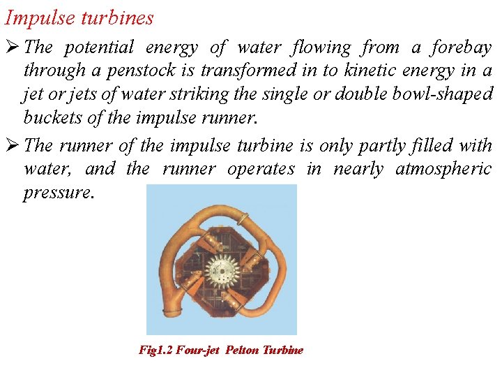
Impulse turbines Ø The potential energy of water flowing from a forebay through a penstock is transformed in to kinetic energy in a jet or jets of water striking the single or double bowl-shaped buckets of the impulse runner. Ø The runner of the impulse turbine is only partly filled with water, and the runner operates in nearly atmospheric pressure. Fig 1. 2 Four-jet Pelton Turbine
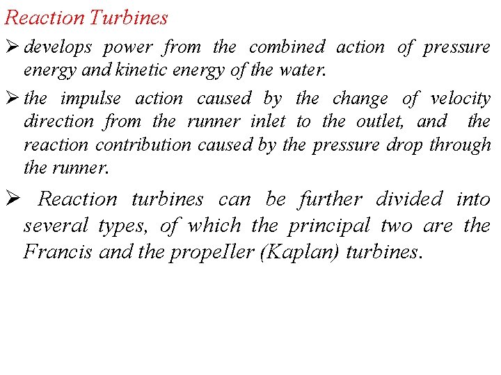
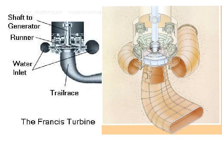
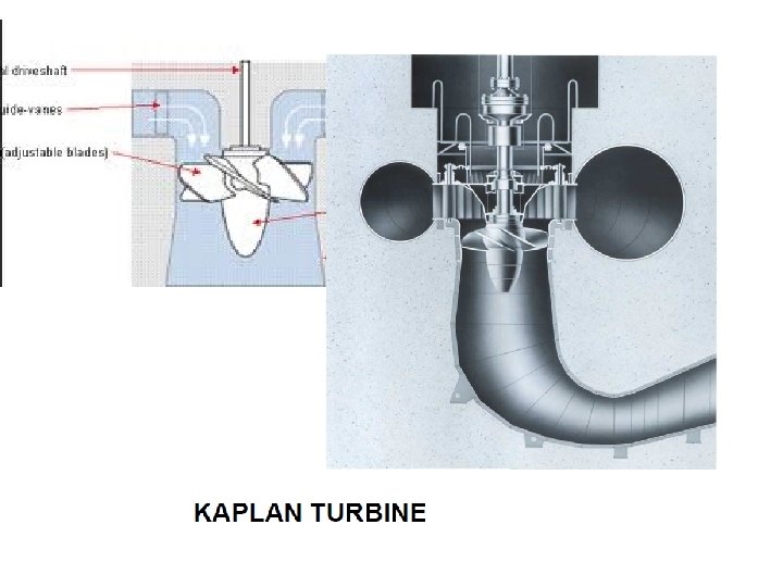
Reaction Turbines Ø develops power from the combined action of pressure energy and kinetic energy of the water. Ø the impulse action caused by the change of velocity direction from the runner inlet to the outlet, and the reaction contribution caused by the pressure drop through the runner. Ø Reaction turbines can be further divided into several types, of which the principal two are the Francis and the prope. Iler (Kaplan) turbines.
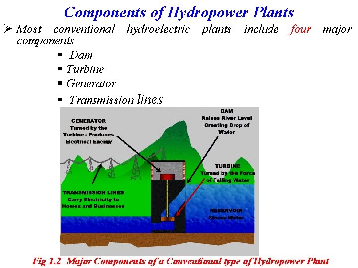
Components of Hydropower Plants Ø Most conventional hydroelectric components § Dam § Turbine § Generator § Transmission lines plants include four major Fig 1. 2 Major Components of a Conventional type of Hydropower Plant
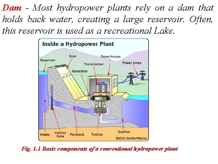
Dam - Most hydropower plants rely on a dam that holds back water, creating a large reservoir. Often, this reservoir is used as a recreational Lake. Fig. 1. 3 Basic components of a conventional hydropower plant
Intake - Gates on the dam open and gravity pulls the water through the penstock, a pipeline that leads to the turbine. Water builds up pressure as it flows through this pipe. Turbine - The water strikes and turns the large blades of a turbine, which is attached to a generator above it by way of a shaft. Generators - As the turbine blades turn, so do a series of magnets inside the generator. Giant magnets rotate past copper coils, producing alternating current (AC) by moving electrons. Transformer - The transformer inside the powerhouse takes the AC and converts it to a higher- voltage current. Power lines - Out of every power plant come four wires: the three phases of power being produced simultaneously plus a neutral or ground common to all three.
Outflow - Used water is carried through pipelines, called tailraces, and re-enters the river downstream. Penstock pipe- The penstock pipe transports water under pressure from the forebay tank to the turbine, where the potential energy of the water is converted into kinetic energy in order to rotate the turbine. The hydropower plant components area is categorized as: • Civil works: Includes dam, powerhouse and spillway(structures used to provide for the controlled release of flows from a dam into a downstream area, typically being the river that was dammed) • Mechanical work: includes turbine, penstock, valves and gates • Electrical and other Equipments: includes transformer, generators and auxiliary equipments
Potential and Developed Hydropower Resources Ø Hydropower potential is generally evaluated in three categories, namely theoretical, technical and economical potential. Ø Theoretical potential is defined as the sum of the annual energy potentially available from all natural flows from the largest rivers to the smallest creek, regardless of the losses. Ø Technical potential is the part of theoretical potential which can be utilized with the current technology regardless of economic and other considerations. This definition of potential subtracts friction losses in water ways and efficiencies in the electromechanical equipment as well as the extreme low heads which are considered as infeasible.
ØEconomic potential is the part of the technical potential which can be regarded as economic when compared to alternative sources of power like oil and coal. ØIt is dependent on the cost of alternative sources. Therefore, it may change with time and should be updated regularly. ØUnion of the Electricity Industry uses a definition called exploitable hydropower potential for the portion of the economical potential which can be harnessed considering environmental and other special restrictions. • The Estimated total technical potential for hydropower in the world is as much as 15955 TWh/year or 4. 8 times greater than today's hydropower production.
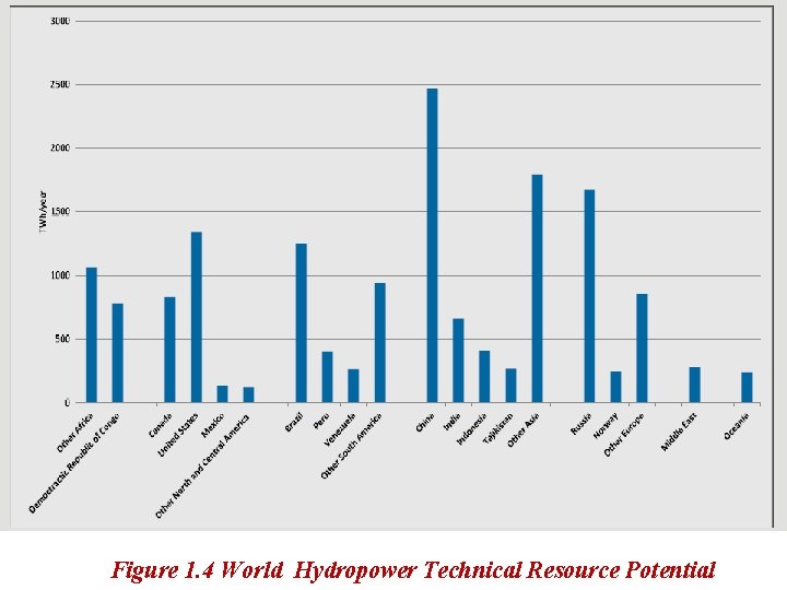
Figure 1. 4 World Hydropower Technical Resource Potential
Classification of Hydro-Electric Power Plants Ø In studying the subject of hydropower engineering, it is important to understand the different types of development. Hydroelectric power plants can be classified in different ways according to their characteristics. Classification According to Operation Mode I. Impoundment Plants Ø Also called ‘storage plants’ or ‘reservoir plants’ is the most common type of hydroelectric power plants. These plants are usually large hydropower schemes and use a dam to store river water in a reservoir.
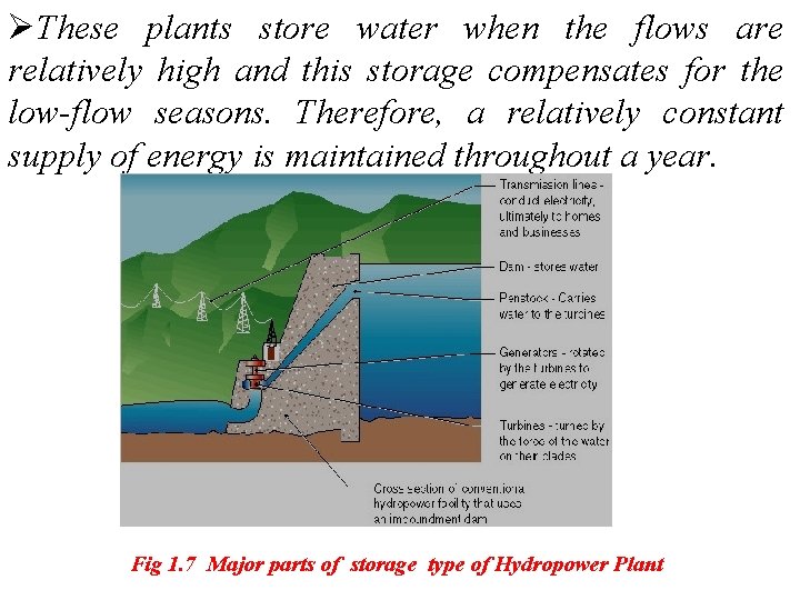
ØThese plants store water when the flows are relatively high and this storage compensates for the low-flow seasons. Therefore, a relatively constant supply of energy is maintained throughout a year. Fig 1. 7 Major parts of storage type of Hydropower Plant
II. Run-of-river Plants ØThis type of plant generally does not have a storage. By means of a diversion weir, water is diverted from the river and given to the transmission canal or sometimes tunnel. ØAt the end of the transmission canal lies a head pond or forebay facilitating a gentle approach to the intake of penstock. Forebays also serve in surge reduction and sediment removal. ØSince these plants do not have storage, energy generation is dependent on the flow in the river.
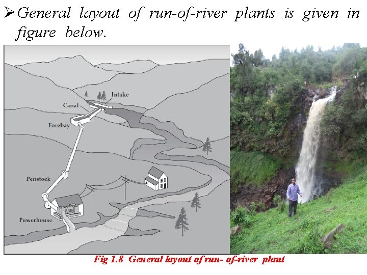
Ø General layout of run-of-river plants is given in figure below. Fig 1. 8 General layout of run- of-river plant
III. Pumped-Storage Plants ØIn contrast to conventional hydropower plants, pumped storage plants reuse water. They store electrical energy as potential energy. ØThey pump water to an upper reservoir at times of surplus energy on an electrical supply grid-typically, at night. This potential energy is then released through a hydro-electrical generator at times of high demand. Therefore, pumped-storage plants function like a large battery. ØThe combined use of pumped storage facilities with other types of electricity generation creates large cost savings through more efficient utilization of base-load plants.
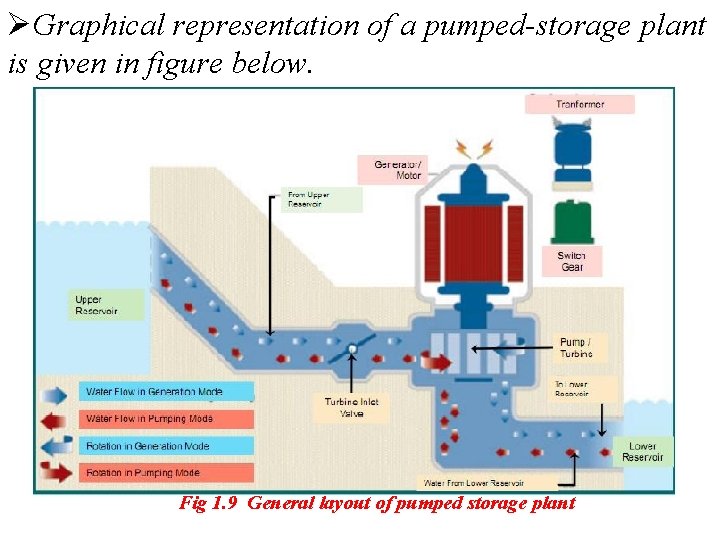
ØGraphical representation of a pumped-storage plant is given in figure below. Fig 1. 9 General layout of pumped storage plant
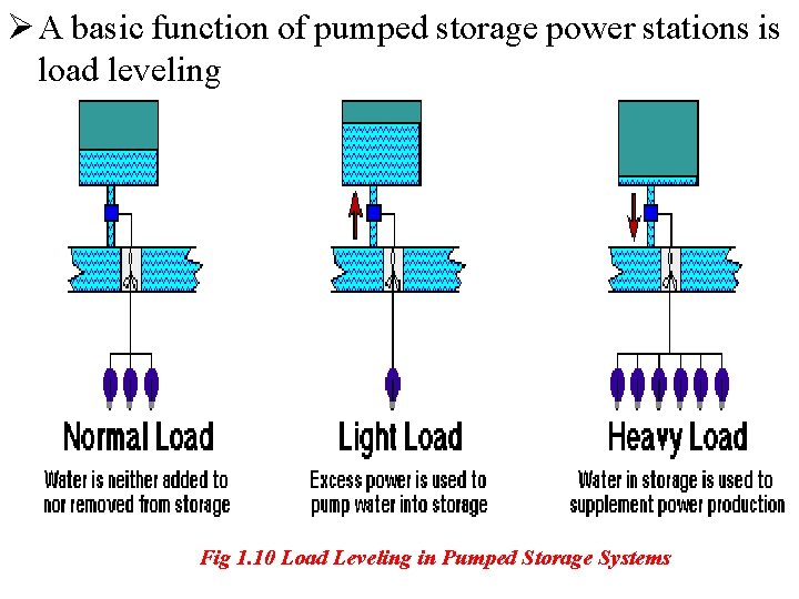
Ø A basic function of pumped storage power stations is load leveling Fig 1. 10 Load Leveling in Pumped Storage Systems
Classification According to the Installed Capacity ØThere is no consensus in the world on the classification of hydropower plants according to installed capacity. They can be classified as large, small, mini, micro and pico hydropower plants. ØMini, micro and pico hydropower plants could be regarded as small hydro power plants; however, they have specific technical characteristics and deserve their own definition. • Different countries and organizations have different definitions. An example is the one made by Natural Resources Canada. According to this definition:
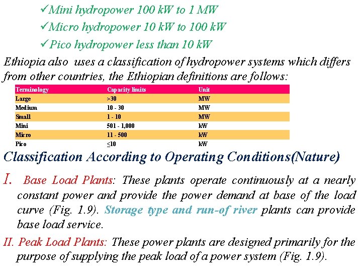
üMini hydropower 100 k. W to 1 MW üMicro hydropower 10 k. W to 100 k. W üPico hydropower less than 10 k. W Ethiopia also uses a classification of hydropower systems which differs from other countries, the Ethiopian definitions are follows: Terminology Capacity limits Unit Large >30 MW Medium 10 - 30 MW Small 1 - 10 MW Mini 501 - 1, 000 k. W Micro 11 - 500 k. W Pico ≤ 10 k. W Classification According to Operating Conditions(Nature) I. Base Load Plants: These plants operate continuously at a nearly constant power and provide the power demand at base of the load curve (Fig. 1. 9). Storage type and run-of river plants can provide base load service. II. Peak Load Plants: These power plants are designed primarily for the purpose of supplying the peak load of a power system (Fig. 1. 9).
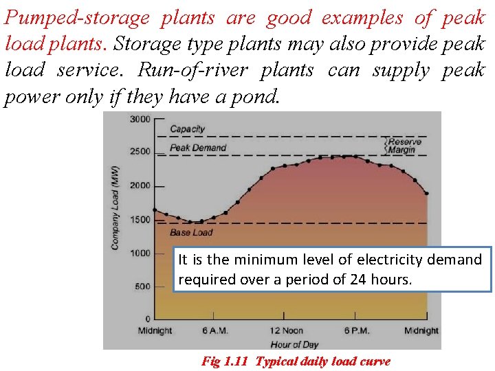
Pumped-storage plants are good examples of peak load plants. Storage type plants may also provide peak load service. Run-of-river plants can supply peak power only if they have a pond. It is the minimum level of electricity demand required over a period of 24 hours. Fig 1. 11 Typical daily load curve
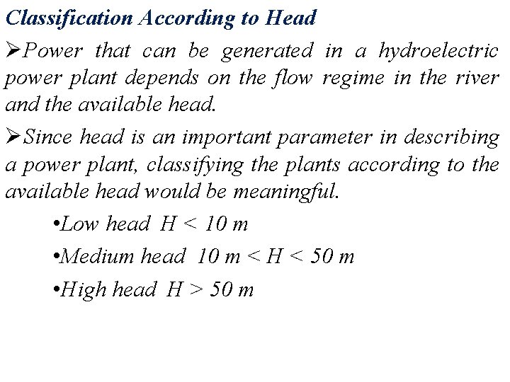
Classification According to Head ØPower that can be generated in a hydroelectric power plant depends on the flow regime in the river and the available head. ØSince head is an important parameter in describing a power plant, classifying the plants according to the available head would be meaningful. • Low head H < 10 m • Medium head 10 m < H < 50 m • High head H > 50 m
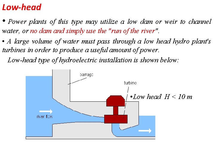
Low-head • Power plants of this type may utilize a low dam or weir to channel water, or no dam and simply use the "run of the river". • A large volume of water must pass through a low head hydro plant's turbines in order to produce a useful amount of power. Low-head type of hydroelectric installation is shown below: • Low head H < 10 m
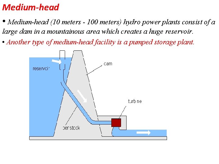
Medium-head • Medium-head (10 meters - 100 meters) hydro power plants consist of a large dam in a mountainous area which creates a huge reservoir. • Another type of medium-head facility is a pumped storage plant.
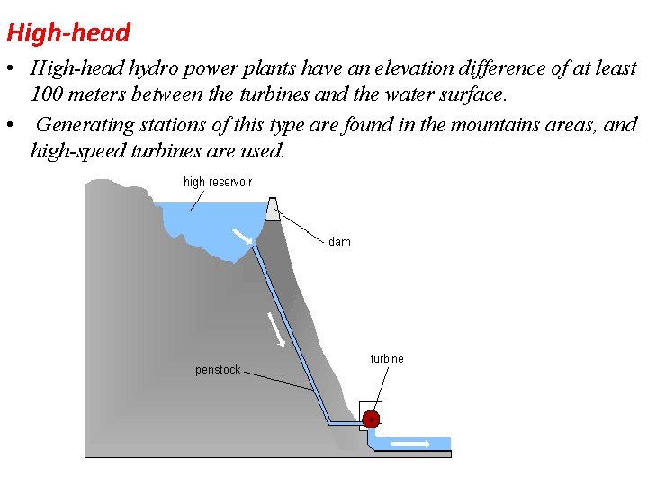
High-head • High-head hydro power plants have an elevation difference of at least 100 meters between the turbines and the water surface. • Generating stations of this type are found in the mountains areas, and high-speed turbines are used.
Site Selection for Hydropower Plants Ø The essential characteristics of a good site are: large catchment areas, high average rainfall and a favorable place for constructing the storage or reservoir. For this purpose, the geological, geographical and metrological conditions of a site need careful investigation. Ø The following factors should be given careful consideration while selecting a site for a hydro-electric power plant.
1. Available water Ø To know the available energy from a given stream or river, the discharge flowing and its variation with time over a number of years must be known. Preferably, the estimates of the average quantity of water available should be prepared on the basis of actual measurements of river flow. Ø The river flow data should be based on daily, weekly, monthly and yearly flow over a number of years. 2. Water-Storage Ø The output of a hydropower plant is not uniform due to wide variations of rain fall. To select the site of the dam, careful study should be made of the geology and topography of the catchment area to see if the natural
3. Head of Water The level of water in the reservoir for a proposed plant should always be within limits throughout the year. 4. Distance from Load Center Most of the time the electric power generated in a hydroelectric power plant has to be used some considerable distance from the site of the plant. For this reason, to be economical on transmission of electric power, the routes and the distances should be carefully considered. 5. Access to Site It is always a desirable factor to have a good access to the site of the plant. This factor is very important if the electric power generated is to be utilized at or near the plant site. The transport facilities must also be given due consideration.

• End of Chapter
- Slides: 49