8086 Syllabus 8086 Microprocessor Introduction to Microprocessor Intel

8086 Syllabus 8086 Microprocessor: Introduction to Microprocessor, Intel Microprocessor families, 8086 Microprocessor architecture, Register Organization, Pin Description, Physical Memory Organization, Modes of operation. 8086 Instruction set & Assembly Language programming: Addressing modes, Instruction set, Assembler directives, simple Programs, Procedures and Macros, 8086 Interrupts.

UNIT - I
 8 bit MP")
• • 4 -Bit MP 4004 in 1971(Not GP ) 8 bit MP 8008 in 1972(Not GP ) 8 bit MP GP 8080 in 1974 fb by 8085 16 bit MP 8086 in 1978

Generation of Computers First generation: First computers were manufactured around 1946. Vacuum tubes were used to build the various circuits required. Those computers were slow, generated lot of heat & required large space. Second generation: Second generation computers used transistor as the basic switching element in early 1950 s. It improved speed, reduced power dissipation & required less space. Third generation computers used Integrated circuits(ICs). Each IC had hundreds of transistors. It was in early 1960 s & up to mid 1970 s. Fourth generation IC technology further improved & LSI(Large scale Integrated circuit) was introduced during 1970 s. LSIs had thousands of transistors in it. This technology introduced Microprocessors & Microcontrollers. Fifth generation These computers use VLSIs(Very Large Scale Integrated circuits) which contain lakhs of transistors in a single chip.

Classification of Computers The digital computers are classified based on speed, storage capacity & word length Microcomputer: These computers have a word length of 8 to 16 bits. They are slow & have less data storage capacity. These are used for dedicated applications. Minicomputer: These computers have a word length of 32 bits. The speed & data storage capacity is moderate. These are used general purpose systems in the field of data processing, process control & industrial applications. Mainframe Compute: These computers have a word length of 64 bits. The speed is very high & data storage capacity is very large. These are used for scientific applications, business data processing & military applications. Super computer: These computers have a word length of 64 bits. The speed is higher than main frame computers. They use artificial intelligence. Objects are used as input/output.

Features of Microprocessor The important features of a microprocessor are 1. Speed: Clock frequency or instructions per second. 2. Instruction set: Number of instructions it can handle. 3. Data bus: The number of data lines it can process at a time. 4. Address bus: The number of address lines which will indicate the maximum memory it can have. 5. Control bus: the number of control lines to control various functions. 6. Register array: The number of registers & their width. 7. Manufacturing technology: PMOS, NMOS & HMOS or CMOS 8. Design technology: CISC or RISC 9. Power: Voltage & current requirement 10. Packaging: Shape, Size & number of pins.

Features of 8086 1. The 8086 is a 16 -bit processor. It means ALU, its internal registers & most of its instructions are designed to work with 16 -bit data. 2. The 8086 has a 16 -bit data bus. 3. The 8086 has a 20 -bit address bus so it can have a maximum of 1 MB of memory. It has 16 -bit I/O address so it can access up to 64 K I/O ports. 4. The data bus and 16 -bit lower order address bus is multiplexed. 5. The 8086 has Fourteen 16 -bit registers. 6. The 8086 requires a clock with 33% duty cycle for its internal timing. Its clock speed is 5 MHz, 8 MHz or 10 MHz. 7. The 8086 has a powerful instruction set with a range of addressing modes. It can perform bit , byte , word & block operations. 8. The 8086 has two mode of operations Minimum & Maximum. In minimum mode it works as a single microprocessor. Where as in maximum mode it work in Multiprocessor configuration.

8086 ARCHITECTURE

The block diagram consists of two internally divided separate functional units. These are BUS INTERFACE UNIT (BIU) & EXECUTION UNIT (EU). They work simultaneously. The division of work between these units speeds up the processing. BUS INTERFACE UNIT (BIU) : The BIU provides the interface to external world. It generates the 20 -bit physical address & handles all the data transfers. 1. It fetches instruction from memory. 2. It reads / writes data from memory / ports. 3. It sends the addresses to memory / ports. 4. It supports an Instruction QUEUE: The BIU fetches up to six instructions bytes belonging to next instructions. These bytes are stored in FIFO - First In First Out register set called as QUEUE. Fetching of the next instructions & execution of the current instruction is done simultaneously. And this QUEUE makes use of pipelining & speeds up processing.

EXECUTION UNIT: The EU is responsible for the instruction execution & has a control circuit to direct its internal operations. 1. It picks up the instructions from the Queue of BIU. 2. It decodes the instructions & decides upon the various operations it has to carry out. It then executes these operations. 3. It uses ALU to perform 16 -bit Arithmetic & logical operations like ADD, SUBTRACT, AND, OR, XOR, INCREMENT, DECREMENT, COMPLEMENT & SHIFT. 4. It updates the status of FLAG register (PSW Register). 5. It performs BIU from where the next instruction or data has to be read.

Register Organization of 8086

The 8086 contains Fourteen 16 -bit registers. They are of different types. 1. General purpose registers: AX , BX , CX , DX. 2. Segment registers: CS , DS , SS , ES. 3. Index registers: SI , DI. 4. Pointer registers: SP , BP , IP. 5. Flag or Program status register. General purpose registers: (AX , BX , CX , DX) 16 -bit register High order 8 -bit Register Low order 8 -bit Register AX AH AL BX BH BL CX CH CL DX DH DL

The general purpose registers are used for temporary storage of data & intermediate results. AX: The register AX is called as Accumulator. During multiplication 8 -Bit x 8 -Bit one of the operand should be in AL and the result will store in AX (AH+AL). In case of 16 -Bit x 16 -Bit the result will store in DX: AX. In case of Division by 8 -Bit the Quotient will be in AL & Remainder in AH , where as in case of 16 -Bit Division the Quotient will be in AX & Remainder in DX. BX: It is used as a Base register. It contains the offset address of the memory location in some addressing modes. CX: It is used as an implicit counter in loop & string instructions. The register CL is used as 8 -bit counter in shift & rotate instructions. DX: It is used to hold the 16 -bit I/O address in I/O instructions.
 FFFFF 00000 = = 64")
Segment registers: (CS , DS , SS , ES) FFFFF 00000 = = 64 KB Extra Segment 64 KB Stack Segment 64 KB Data segment 64 KB Code Segment 1111 1111 0000 0000
 There are two index registers Source Index (SI) &")
Index registers: (SI , DI) There are two index registers Source Index (SI) & Destination Index (DI). They acts as general purpose registers also during string instructions. Pointer registers: (SP , BP , IP) There are three pointer registers. They are Instruction pointer (IP), Stack pointer(SP) & Base pointer (BP). They are associated with Code segment & stack segment. 1. The IP register keeps the track of 16 -bit offset address of the next instruction to be executed. 2. The SP register points the top of the stack. 3. The BP register is used as general purpose as well bottom of the stack.
 Program status register Six are status Flags: Three are control flags: OF")
Flag (or) Program status register Six are status Flags: Three are control flags: OF , SF , ZF , AF , PF , CF. DF , IF , TF
: It is set if there is a carry out of the")
1. Carry Flag(CF): It is set if there is a carry out of the most significant bit position resulting from an addition or if a borrow is needed at MSB during subtraction. If no carry out or borrow is needed , the carry flag is reset. 2. Parity Flag(PF): if the lower order 8 -bits of the result of an operation contains even number of 1’s then this bit set to “ 1”. If the lower order 8 -bits contains odd number of 1’s then this bit remains to be “ 0”. 3. Auxiliary carry flag(AF): It is set to 1 if there is a carry out of bit 3 to bit 4 resulting from an addition or borrow is required from bit 4 to bit 3 for subtraction. 4. Zero flag(ZF): It is set to “ 1” if the result of an arithmetic or logic operation is zero. In case of non-zero it remains to be “ 0”. 5. Sign flag(SF): It is set to “ 1”the result is odd. it is set to “ 0”, if the MSB of the result is even during any operation. This flag is used with signed numbers. 6. Overflow flag(OF): In case of a signed arithmetic operation, the overflow flag is set to “ 1”, if the result is too large to fit in the number of bits available to accommodate it. The overflow flag has no significance in unsigned arithmetic operation.
: It is used for single step control. It allows")
7. Trap or Trace Flag(TF): It is used for single step control. It allows user to execute one instruction of a program at a time for debugging. When TF=1, a program can be run in single-step mode. The TF flag is restored to the state in which was before the interrupt occurred. 8. Interrupt flag(IF): It is an interrupt Enable/Disable flag. If it is set to “ 1” interrupt is enabled, if it is reset to “ 0 “ then the interrupt is disabled. 9. Directional Flag(DF): It is used during string operations. If it is set to “ 1” string bytes are accesses from higher memory address to lower memory address. When it is “ 0” the string bytes are accesses from lower address to higher address.

Default Segment & Offset Registers Default Segment Offset Memory operation CS IP Instruction fetch SS SP, BP or effective address Using BP as one of the register Stack operation DS BX/SI/DI or effective address using above registers General data access DS SI Source string data access ES DI Destination string data access

Generating 20 -bit Physical address
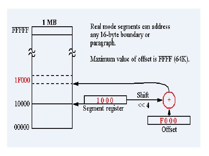

Advantages of Memory Segmentation 1. It allows the memory capacity to be 1 MB even though the actual addresses to be handled by instructions are 16 -bits 2. It allows use of separate memory areas for program, data & stack, thus the protection of these is possible. 3. For large programs , it can use multiple segments for program code, Data & Stack. 4. Program relocation can be very easily done.

Physical Memory organization FFFFFH FFFFDH FFFFEH FFFFCH 512 KB 00003 H 00002 H 00001 H 00000 H [ Higher bank( Odd Bank) BHE A 0 Type of data transfer and bank selection 0 0 16 ‘=-bit data transfer, both banks selected 0 1 8 -bit data transfer, odd bank selected 1 0 8 -bit data transfer , even bank selected 1 1 No data transfer , both banks disabled Lower bank( Even Bank)

8086 Pin Diagram

The pins & signals of 8086 can be classified as into five groups, they are as follows: 1. Address / Data bus 2. Address / status bus 3. Control & status signals 4. Interrupts & externally initiated signals. 5. Power supply & clock frequency signals. 1. Address / Data bus [AD 0 -AD 15 (input/Output): Pins 16 to 2 & 39] These signals are bi-directional & time multiplexed. If a bus carries different types of signals at different times then it is called time multiplexed. During the first clock cycle, during ALE, they contain address information (A 0 to A 15) & in the remaining clock cycles they contain data (D 0 to D 15). During hold acknowledge they will be in high impedance state. 2. Address / status bus [A 16/S 3 -A 19/S 6(Output/Tristate): Pins 38 to 35] These signals are output & time multiplexed. During the first clock cycle, during ALE, they contain address information (A 16 -A 19). In the remaining clock cycles they contain status information(S 3 -S 6). During HOLD acknowledge they will be high impedance a state.

S 3 S 4 S 5 S 6 Signals are as below: S 3 & S 4 indicate which segment register is being used for generating 20 -bit physical address S 3 S 4 Segment Register 0 0 ES 0 1 SS 1 0 CS (None in the case of I/O port access) 1 1 DS S 5 indicates the current status (0 or 1) of interrupt flag. S 6 is always “ 0” and is not used. 3. Control & Status Signals 1. RD: Read [output/tri state]: pin 32 A low on this signal indicates read operation from memory or I/O. during HOLD acknowledge it will be in high impedance state.
: pin 34 It is an")
2. BHE/S 7: Bus High Enable/S 7 9 output): pin 34 It is an output & time multiplexed. During the first clock cycle it contains BHE. In the remaining cycles it contains S 7. BHE is active low signal. When low it enables the MSB data bus (D 8 -D 15) during read/ write operation. S 7 is always High. 4. Interrupts & externally initiated signals 1. NMI: Non mask able interrupt(input): Pin 17 This is a non mask able interrupt request to CPU from external devices. It is a positive edge triggered signal. It cannot be disabled using interrupt flag. 2. INTR: Interrupt (Input): Pin 18 It is a mask able interrupt request to CPU from external devices. It is a level triggered signal. It can be enabled or disabled using interrupt flag. To enable set the interrupt flag. 3. RESET: Reset (input): Pin 21 This is a input signal which resets the u. P. This should be held high for at least 4 clock cycles.
: Pin 22 This input signal indicates to the CPU whether")
4. READY: Ready (input): Pin 22 This input signal indicates to the CPU whether memory or I/O device is ready for data transfer. If it is High then they are ready. If it is Low then CPU waits for it to become High. 5. TEST: test (input): Pin 23 This input signal is used to synchronize external hardware. It is tested by WAIT instruction. If it is high, WAIT instruction waits for it to become low. If it is low WAIT instruction will be NOP. It is normally connected to 8087 coprocessor. 6. MN/MX: Minimum / Maximum (input) : Pin 33 This signal selects the minimum or maximum mode operation of the u. P. If it is low it works in maximum mode and if it is high works in minimum mode. 5. Power supply & clock frequency signals. 1. GND: Ground (input) : Pin 1 & 20 This input should be connected to the negative terminal of the DC power supply. 2. CLK: clock (input): Pin 19 This input clock signal provides the basic timing for the u. P with 33% duty cycle.
 : Pin 40 This input is connected to")
3. Vcc : power Supply (input) : Pin 40 This input is connected to the positive terminal of +5 V DC power supply.

Minimum Mode Configuration of 8086 There are 8 signals which are used in minimum mode of 8086. the 8 signals generated by minimum mode belong to control, status, interrupt & externally initiated function. They are as follows: 1. ALE : Address Latch Enable (output): Pin 25 This signal is used to latch the addresses & BHE signal. This way A 0 -A 15 gets separated from D 0 -D 15, A 16 -A 19 gets separated from S 3 -S 6 & BHE gets separated from S 7. 2. DEN : Data Enable (output): Pin 26 This signal is used to activate the data transceivers. It is an active low signal. When high data transceivers will be in high impedance state. 3. DT/ R : Data Transmit/Receive (output): Pin 27 This signal is used to control the direction of data bus on data transceivers. When it is high data is transmitted from CPU and when low data is received by CPU. 4. M / IO : Memory / Input-Output (Output/tri state): Pin 28 This signal selects memory or I/O Operation. When high memory & when low then I/O is selected. This will remain High impedance during hold acknowledge.
: Pin 30 A low on this")
5. WR : Write ( Output/ tri state): Pin 30 A low on this signal indicates that data on the data bus is valid & can be written into memory or I/O. during hold acknowledge it will remain in high impedance state. 6. INTA : Interrupt Acknowledge (Output) : Pin 24 This signal is activated by CPU in response to INTR signal. This signal is actually acknowledging the interrupt received on INTR. It is used by the interrupting device to send interrupt type number to the CPU. 7. HLDA : Hold Acknowledge(Output): Pin 30 This signal will be made high by CPU to indicate that hold request has been accepted & CPU relinquishes the buses so that they can be used by requesting device. 8. HOLD : Hold (Input) : Pin 31 This input indicates a request for the bus by I/O devices or DMA controller. If it is high , u. P stops executing instructions, & puts its buses into high impedance.

Maximum Mode Configuration of 8086 There are 8 signals which are used by maximum mode of 8086. these signals are related to status instruction queue & multiprocessor configuration control. These are described as below: 1. QS 1, QS 0 : Queue Status (Output) : Pin 24 & 25 These signals indicate the status of instruction queue during the previous clock cycle. These are accessed by the coprocessor 8087. QS 1 QS 0 Function 0 0 Queue is idle 0 1 First byte of op code 1 0 Queue is empty 1 1 Subsequent byte of op code 2. S 0 , S 1 , S 2 : status bits (output) : Pin 26, 27 & 28 These signals indicate the status of current bus cycle i. e. , type of machine cycle. In a machine cycle a specific type of activity takes place. These signals are decoded by bus controller.

S 2 S 1 S 0 Machine Cycle 0 0 0 Interrupt acknowledge 0 0 1 I/O Read 0 1 0 I/O Write 0 1 1 Halt 1 0 0 Instruction (Op-Code) Fetch 1 0 1 Memory read 1 1 0 Memory write 1 1 1 Passive (Inactive) 3. LOCK: Lock (output) : Pin 29 This signal indicates that an instruction with lock prefix is being executed & system bus cannot be used by other processors or controllers. This signal is useful in multi processor configuration where system bus is shared. CPU can give the bus to other processors on request, during execution of an instruction also. But lock prefix to instruction ensures that system bus is released only after completion of the instruction.

4. RQ 1 / GT 1 , RQ 0 / GT 0 : Request / Grant (Input output) : Pin 30 & 31 These signals are used as inputs & outputs. Other processors send the request for the system bus(input) & 8086 u. P sends the Grant for that request, using these signals. Both signals are similar hence two requests can be given simultaneously. , RQ 0 / GT 0 has the higher priority.

Minimum mode configuration

In this mode MN/MX is connected to +5 V. 8284 is a clock generator. It provides three output signals CLK , Ready & Reset which are connected to CPU. CLK signal is derived from the basic clock of crystal connected to 8284. RDY and RESET signals are synchronized by 8284 & given as inputs to CPU. Wait state generator controls RDY signal. RESET signal becomes active on power up or on pressing the reset switch. The 74 LS 244 is a unidirectional buffer for control signals. The three latches 74373/8282 are used to de-multiplex address A 0 -A 19 & BHE from AD 0 -AD 15, A 16/S 3 -A 19/S 6 & BHE/S 7. The two 74245/8286 transceivers are bidirectional buffers for data bus.

Maximum mode configuration

In this mode MN/MX is connected to ground. All the blocks are same as minimum mode except 8288 bus controller. This controller generates various control signals. CLK, S 0, S 1, S 2 are the inputs to 8288. the output signals from 8288 are DEN, DT/R, ALE, MRDC, MWTC, AMWC, IORC, IOWC, AIOWC & INTA. Out of these signals DEN, DT/R, ALE & INTA signals are same as generated by CPU in minimum configuration. MRDC & MWTC are for memory read & write operations. AMWC is for advanced memory write. IORC & IOWC are for I/O read & write operations. AIOWC is for advanced I/O write

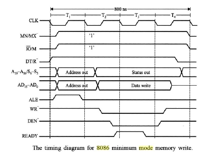
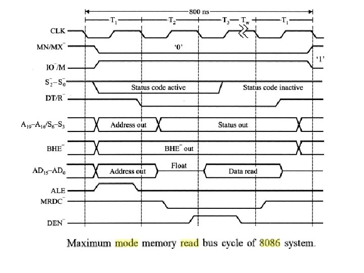
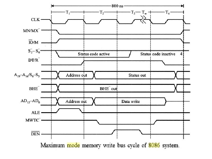
Timing Diagram

END OF UNIT - I

UNIT - II

INSTRUCTIONS One of the important features of u. P is its instruction set. It includes different types of instructions. An instruction basically is a command given to CPU by the programmer, for performing a specific operation. The instruction of a u. P not only specifies the type of instruction but the operands also. An operand is the data on which operation will be performed. Hence an instruction will consist of two fields, first field is Op-code (type of operation) and the second is operands. The instruction , written in assembly language, should be converted to binary code. In order to do this , certain rules are followed which are called Instruction Formats.

Addressing modes of 8086 The various addressing modes of 8086 are as follows: 1. Immediate addressing mode In this mode the operand is specified in the instruction itself. Ex: MOV AL, 55 H MOV BX, 0 ABCDH 2. Register addressing mode In this mode the operand is specified in the register which is used by the instruction. Except IP all registers can be used Ex: MOV AL, BL MOV CX, DX 3. Implicit addressing mode In this addressing mode the registers are used for specifying the operands but these registers are predefined. Hence there is no need to mention the name of registers in the instruction. Ex: DAA MUL BX

4. Direct addressing mode In this mode the offset address of the operand is specified in the instruction i. e. , the operand is available in the memory location & its 16 -bit offset address or name is given in the instruction. Ex: MOV RESULT, AL MOV BL, NUM MOV RES, AX 5. Register indirect addressing mode In this mode the offset address of the operand is specified in the register, which is used by the instruction. Registers BX, SI & DI can be used to specify the 16 -bit offset address of the operand. Ex: MOV AL, [BX] MOV AX, [BX] MOV BYTE PTR[SI], 10 H MOV WORD PTR[SI], 10 H

6. Register relative addressing mode In this mode the effective address of the operand is specified using a register & 8 -bit/16 -bit constant called displacement. The registers BX, SI, DI & BP can be used. The 16 -bit effective address of the operand is calculated by adding the contents of register & displacement. It is generally used to address an array of data. Ex: MOV AL, [BX]100 H MOV ARRAY[DI], AL 7. Base index addressing mode In this mode the effective address of the operand is specified using two registers. One of them will be base register BX or BP and the other will be index register SI or DI. The 16 -bit effective address of the operand is calculated by adding the content of the two registers. Ex: MOV DX, [BX][SI] or MOV DX, [BX + SI] MOV [BP + DI], AL
 Base index with displacement In this addressing")
8. Relative base index addressing mode (or) Base index with displacement In this addressing mode the effective address of the operand is specified using base register, index register & 8 -bit/16 -bit displacement. The 16 -bit effective address is calculated by adding three parameters i. e. , content of base register BX or BP, content of index register SI or DI & 8 -bit or 16 -bit displacement. This mode is very rarely used. Ex: ADDRESSING MODES FOR PROGRAM MEMORY A program is executed in a sequential manner. But at times the program control has to be transferred to other memory location in the same segment or other segments. JMP & CALL instructions are used for this purpose. The address to which control is to be transferred is specified in the operand field of instruction. The method of this specification or addressing modes under this are given below
 mode In this mode, the instruction to which control has")
1. Intra segment direct(relative) mode In this mode, the instruction to which control has to be transferred lies in the same segment. The content of IP & displacement (+ve or –ve) are added to calculate the effective address of instruction. Ex: JMP NEXT JC NEXT CALL MPY JNC FORWARD 2. Intra segment indirect mode In this mode the instruction to which control has to be transferred lies in the same segment. The 16 -bit offset address of the instruction is specified in a register. Any register except IP can be used. Ex: JMP CX JMP WORD PTR[BX]

3. Inter segment direct mode In this mode the instruction to which control has to be transferred lies in other segment i. e. , any where in the 1 MB memory area. The label specified in the instruction lies in other segment. Ex: JMP CONTINUE; Here CONTINUE lies in other segment. 4. Intra segment indirect mode In this mode the instruction to which control has to be transferred, lies in other segment. The current instruction uses a register which points to a four location memory area in the data segment. The first two locations contain the offset address of instruction, which is loaded in IP. The next two locations contain the starting address of the segment and is loaded in CS register. Thus, control will be transferred to other segment. Ex: JMP DWORD PTR [SI] -IP is replaced with a word pointed by SI. -CS is replaced with a word pointed by SI + 2. Hence , control will be transferred to an instruction in other segment.

ADDRESSING MODES FOR I/O PORTS Microprocessors will not be connected to the I/O devices directly. They are connected through I/O ports. 8086 can address up to a max of 64 K(65536) input & output ports. The address space is from 0000 H-FFFFH. IN & OUT instructions will be used to read & write from these ports. There are two ways of addressing I/O ports. 1. Fixed port (or) Direct port addressing In this mode only 256 (00 H-FFH) ports can be addressed & the port numbers will be given in the instruction itself. Ex: IN AL, 40 H OUT 0 F 0 H, AL IN AX, 28 H 2. Variable port (or) Indirect port addressing In this mode, all 64 K ports can be addressed. The port address should be available in register DX before executing IN/OUT instructions. Ex: IN AL, DX OUT DX, AX

CLASSIFICATION OF ASSEMBLER DIRECTIVES Based on the type of operation , assembler directives are classified as given below 1. Data definition & storage allocation directives DB, DW, DD, DQ, DT 2. Program organization directives SEGMENT, ENDS, ASSUME 3. Alignment directives EVEN, ORG 4. Program end directive END 5. Value returning attribute directive OFFSET

6. Procedure definition directives PROC, ENDP 7. Macro definition directives MACRO, ENDM, EQU 8. Data control directives PUBLIC, EXTRN, PTR 9. Branch displacement directive. LABEL 1. DB: DEFINE BYTE Format: Variable name DB value 1, value 2, …. Operation: This directive is used to define a byte type variable. Single or multiple variables can be defined

Example 1. NUM DB 55 H: Reserve one memory location by name ‘NUM’ and initialize it to 55 H 2. MES DB ‘BE HAPPY’: Reserve 8 bytes for ASCII codes of characters used in BE HAPPY. 3. ARRAY DB 5, 10, 15, 20, 25: Reserve 5 memory locations for ARRAY and initialize then with decimal values 5, 10, 15, 20 & 25. 2. DW: DEFINE WORD Format: Variable name DW value 1, value 2, …. Operation: This directive is used to define a WORD type variable. Single or multiple variables can be defined
 memory for variable")
Example 1. RES DW ? : Reserve one word (two bytes) memory for variable named ‘RES’. No initialization is required. 2. NUM DW ‘ 35’: Reserve one word memory for variable named NUM and initialize with ASCII equivalent of ‘ 3’ (33 H) and ‘ 5’ (35 H). So word memory will be initialized to 3335 H 3. ARRAY DW 50 H, 2500 H: Reserve two words memory for variable array & initialize them with 0050 H & 2500 H. 3. DD: DEFINE DOUBLE WORD Format : Variable name DD value 1, value 2, …. Operation : This directive is used to define a double word type ( 4 bytes) variable. Single or multiple double word variables can be defined.
 for variable NUM")
Examples: 1. NUM DD 0: Reserve four bytes ( double word) for variable NUM & initialize to Zero. All four bytes are Zero. 2. STRING DD ‘ 35’: Reserve four bytes for variable STRING. First two bytes will be initializes to 0 s and next two bytes with 33 H & 35 H. Note: DD cannot be used to define a variable with more than two ASCII characters. 4. DQ: DEFINE QUAD WORD Format: Variable name DQ value 1, value 2, …. Operation : This directive is used to define quad word type ( 4 words or 8 bytes) variable. Single or multiple quad word variables can be defined. Examples: 1. NUM DQ 123456789 ABCDEF 0 H: Reserve 8 bytes of memory locations& initialize them with F 0 H, DEH, …. 12 H starting with LSB.

2. STRING DQ ‘ 35’: Reserve 8 bytes of memory locations first 6 bytes are initialized as Zeros and next two bytes with ‘ 3’ (33 H) and ‘ 5’ (35 H). Note: DQ cannot be used to define a variable with more than two ASCII characters. 5. DT: DEFINE TEN BYTES Format: Variable Name DT value 1, value 2, …. Operation: This directive is used to define ten bytes type variable. Single or multiple ten byte variables can be defined. Examples: 1. NUM DT ? : Reserve ten bytes of memory. Initialization not done. 2. NUM DT 0 : Reserve ten bytes of memory. Initialization to Zero. 3. NUM DT 123456789 ABCDEF 01234 H: Reserve ten bytes of memory. Initialize with above data from 34 H as LSB Note: DT cannot be used to define a variable with more than two ASCII characters. Example : NUM DT ‘ 35’
 Operation: This directive is")
6. DUP: DUPLICATE Format: Variable name Date type Num DUP(value) Operation: This directive is used to initialize several memory locations and assign values to these locations. Num is the format indicates the number of memory locations to be initialized. Example: 1. LIST DW 8 DUP(55 AAH): This statement reserves 8 words of memory. They are all initialized with value 55 AAH. 2. LISTA DW 1234, 55 H, 5 DUP(5678): This statement reserves 7 words of memory. First word is initialized with 1234 H, next word with 0055 H and next 5 words with 5678 H. 3. TABLE DB 10 DUP(0), 35 H: Reserve 11 bytes of memory. First 10 locations are initialized with zero and 11 th location with 35 H.

7. END Format: 1. END 2. END label. Operation: This directive is used to inform the assembler the end of a program. Hence this is the last statement of every program. Any statements after this will be ignored. Label field is optional. It is the label of first instruction of program. Example: 1. END 2. END START: This indicates the end of a program whose execution began from the instruction whose label was START. 8. ENDM : END OF MACRO Format: ENDM Operation: This directive informs the assembler the end of macro

Example : ENDM Note: ENDM is to be used with directive MACRO as a pair 9. ENDP : END OF PROCEDURE Format : Procedure name ENDP Operation: This directive informs the assembler the end of procedure whose name is specified before ENDP. Example: MULTIPLY ENDP: End of procedure whose name is MULIPLY. Note: ENDP is to be used with directive PROC as a pair 10. ENDS: END OF SEGMENT Operation: This directive informs the assembler the end of a segment whose name is specified before ENDS. Example: 1. CODE ENDS: End of segment whose name is CODE 2. DATA ENDS: End of segment whose name is DATA

11. EQU: EQUATE Format: 1. Variable name EQU expression 2. String name EQU ‘String’. Operation: This directive is used to equate a variable name with another variable name or immediate data. Similarly, string name will be equated to ASCII codes of characters in a string. Example: 1. PORT EQU 8000 H: Variable name PORT has a value 8000 H. 2. STRING EQU ‘HYDERABAD 500006’: STRING is equated to ASCII codes of H, Y, D, E, R, A, B, A, D, , 5, 0, 0, 6. 3. ASCII ADJUST EQU AAS: ASCII ADJUST is equated to AAS.

12. ASSUME Format: ASSUME Segment register: segment name , segment register: segment name. Where ASSUME is a assembler directive. Segment register: One of four segment registers CS or DS or SS or ES Segment name : Name of logical segment as defined by user. Operation: This directive is used to inform the assembler the name of logical segment should use for a particular segment. Example: ASSUME CS: CODE, DS: DATA, SS: STACK, ES: EXTRA 13. EVEN: ALIGN ON EVEN MEMORY ADDRESS Format: EVEN Operation: This directive is used to inform assembler to increment location counter to next even memory address if it is not already at an even address. This directive can be used in both code & data seg.
 DATA SEGMENT")
Example: DATA SEGMENT NUM DB 55 H LIST DW 50 DUP(0 H) DATA SEGMENT NUM DB 55 H EVEN LIST DW 50 DUP(0 H) 14 EXTRN: EXTERNAL Format: 1. Format for Data segment EXTRN variable 1: data type 1, variable 2: data type 2, . . 2. Format for Code segment EXTRN address 1: NEAR or FAR, address 2: NEAR or FAR, . .

Operation: This directive can be used in data segment or code segment. By using this directive a program can use the variables defined in other program module. They will be defined as PUBLIC in that module. Type of the variable (DB, DW, …) should be specified. Constants defined with an EQU in another module are specified as type ABS. In code segment it informs the assembler that label (address) used is in another module. Here you have to specify the type as NEAR or FAR. JMP or CALL will use such labels. This directives is always used with directive PUBLIC. They are very useful in modular programming. Example : DATA SEGMENT EXTRN NUM 1: BYTE, NUM 2: WORD, NUM 3: ABS Here NUM 1, NUM 2 & NUM 3 are variables available in other program modules and defined as DB, DW & EQU respectively. DATA ENDS

CODE SEGMENT EXTRN KBRD: FAR : START: MOV AX, DATA MOV DS, AX : MOV AL, NUM 1; Get NUM 1 byte from other program module MOV BX, NUM 2; Get NUM 2 word from other program module MOV DX, NUM 3; Get NUM 3 word from other program module : CALL KBRD : CODE ENDS : END START

15. LABEL: LABEL Format: Label Name LABEL Label type For a data reference, label type should be BYTE, WORD etc. For a Jump/Call address, label type should be NEAR or FAR. Operation: This directive is used to assign a name to the current location counter. Example: 1. DATA SEGMENT ARRAY DW 10 DUP(0) NXT LABEL WORD DATA ENDS ; Reserve 20 bytes of memory ( location counter=14 h) ; 14 h is assigned as word to NXT

2. CODE SEGMENT : MOV AX, CX MOV BX, DX ENTER LABEL FAR MOV SI, DI ; Assign value of current location to ENTER. Now you ; can jump to this instruction from other code segment NOTE: If ENTER is not defined as LABEL and instead ENTER is the name of instruction as defined below ENTER: MOV SI, DI Then you cannot jump here from other code segment. 16. MACRO: MACRO Format: Macro Name MACRO ( Argument 1, …Argument N) Operation: This directive indicates the start of a MACRO. Arguments are dummy variables and are optional. In the program it is called by its name and actual argument. It is used with directive ENDM as a pair.

Example: DISP MACRO MSG MOV AH, 09 LEA DX, MSG INT 21 H ENDM 17. OFFSET: OFFSET Format: OFFSET variable name Operation: This directive is an operation and informs the assembler to determine the displacement of the specified variable from the start of the segment. It is used to load the offset address of a variable into the register. Now, the variable can be accessed by indirect or index addressing modes which use this register.

Example: DATA SEGMENT ARRAY DB 10, 20, 30, 40, 50 : DATA ENDS CODE SEGMENT : : MOV BX, OFFSET ARRAY MOV AL, [BX] MOV DL, [BX+2] ; DEFINE ARRAY OF 5 NUMBERS ; load offset address of ARRAY in register BX ; Get the first element from array ; Get the third element from array.

18. ORG: Originate Format: 1. ORG Numeric value 2. ORG$ + Numeric value Operation : This directive is used to assign a value to the location counter. The location counter is used to keep the track of how many bytes, an instruction or variable is away from the start of respective segments. The location counter is set to zero automatically at the start of a new segment. Now, you could set it to any value using this directive. It is used any where in the segment. A $ is used to represent the value of current location counter. Examples: 1. DATA SEGMENT ; start of a new segment ORG 200 H ; set location counter to 200 H

2. DATA SEGMENT ; start of a new segment : : ORG $+100 H ; increment current location counter by 100 H 19. PROC: PROCEDURE Format: procedure name PROC NEAR/FAR Operation: This directive indicates the start of a procedure. NEAR procedure means the procedure and the instruction which calls the procedure are in the same code segment. FAR procedure means that procedure is in a different code segment from the code segment which contains its call. Example: 1. MPY PROC NEAR Here MPY is a near procedure. So it can be called from same segment in which it lies. 2. DIVIDE PROC FAR Here DIVIDE is a FAR procedure. It can be called from any other code segment.

Note: 1. PROC and ENDP are used together as a pair. 2. The program code is enclosed with in the directives PROC & ENDP. MPY PROC NEAR MOV AL, BL : RET MPY ENDP 20. PTR: POINTER Format: Date type PTR Operation: This directive is used to specify the type of memory access. This is done when the data type of operand is not clear. For example, INC[DI] does not tell you whether it is a byte increment or
![word increment. It can be made clear by using PTR directive. INC [DI] will](http://slidetodoc.com/presentation_image_h/34729e73a38b672ac0863cdc6bd81e80/image-74.jpg "word increment. It can be made clear by using PTR directive. INC [DI] will")
word increment. It can be made clear by using PTR directive. INC [DI] will be written as INC BYTE PTR[DI] for byte increment and as INC WORD PTR[DI] for word increment. 21. PUBLIC: PUBLIC Format: 1. For data segment PUBLIC variable 1, ……, variable N 2. For code segment PUBLIC label 1(address), …. , label N(address) In data segment it informs the assembler that specified variable can be accessed from other modules so by using this directive these variables can be accessed from other program modules. In data segment of other program modules these variable will be declared as External. In code segment it informs the assembler that specified label (address)can be accessed from other program modules.

In code segment of other program modules these will be declared as External. Example : DATA SEGMENT PUBLIC NUM 1, NUM 2, NUM 3 ; NUM 1, NUM 2, NUM 3 are declared as PUBLIC. They can be used by other program modules NUM 1 DB 55 H NUM 2 DW 1234 H NUM 3 EQU 6789 H DATA ENDS

In code segment use of PUBLIC directive is as follows CODE SEGMENT PUBLIC KBRD PROC FAR: MOV AH, 1 INT 21 H RET KBRD ENDP : : CODE ENDS

21. SEGMENT: SEGMENT Format: Segment name SEGMENT Operation: It is used to indicate the start of a logical segment. It is used with ENDS. Hence SEGMENT and ENDS are used as pair. Example: DATA SEGMENT ; Start of segment whose name is DATA : : DATA ENDS ; End of segment whose name is DATA

PROCEDURES & MACROS PROCEDURE: The Procedure or subroutine or subprogram is a group of instructions performing a particular subtask of repeated occurrence. This group of instructions is used several times in a program. In order to avoid writing these instructions each time , they are stored separately in a memory area as a procedure and called from main program, whenever required, using CALL instruction. This saves memory space but calling process takes more time. The procedure will have RET as the last instruction. On execution of this instruction, control will return to the next instruction in main program. This is made possible by saving the return address (address of next instruction after CALL) on stack when CALL is executed. On execution of RET return address is retrieved from stack.

TYPES OF PROCEDURES 1. Single procedure 2. Nested procedure 3. Re-entrant procedure 4. Recursive procedure 1. Single procedure Main Program CALL Procedure RET

2. Nested Procedure CALL Proc 1 CALL Proc 2 Main Program RET Procedure-1 Procedure-2 3. Re-Entrant Procedure CALL Proc-1 Main Program Interrupt occurs RET Proc-1 CALL Proc-1 IRET ISR

4. Recursive Procedure CALL Proc-1 MAIN Program CALL Proc-1 RET Proc-1

MACROS: As mentioned earlier a procedure is useful when it contains several instructions. If the number of instructions are less then it becomes disadvantageous. In such a case MACRO is used. A MACRO is also a group of instructions performing a particular subtask of repeated occurrence. It is given a name and stored in a separate memory area. Whenever this MACRO is used by its name in the program, the assembler replaces it with the group of instructions. Hence assembler will generate the machine code each time MACRO is used. This code will be in a proper sequence hence no need of using CALL & RET instructions as in the case of procedure. Only disadvantage is that program takes up more memory.

Comparison between Procedures & Macros S. No Procedure Macro 1 It takes less memory It takes more memory 2 Its execution time is more Its execution time is less 3 It is defined using PROC & ENDP directives It is defined using MACRO & ENDM directives 4 It is accessed by CALL & RET instruction during the program It is accessed by its name , given to MACRO when defined, during program assembly. 5 It’s instructions are machine coded only once It’s instructions are machine coded each time it is called 6 Parameters are passed through registers, memory, pointers & stack Parameters are passed as a part of statement which calls macro. 7 Program flow branches to procedure and comes back to main program Program flow does not branch as MACRO statement is replaced by its group of instructions. Program flow will be sequential. 8 It will make use of stack It will not make use of stack 9 It is used when number of repetitive instruction are more It is used when number of repetitive instruction is less.

Interrupt structure of 8086

8086 Interrupt Types The 256 interrupts of 8086 are divided into three groups 1. Type 0 to Type 4 Interrupts: These are used for fixed operations and hence called Dedicated interrupts. 2. Type 5 to Type 31 Interrupts: These are not used by 8086. They are reserved and will be used by 80286 processor onwards and hence called Reserved Interrupts. 3. Type 32 to Type 255 Interrupts: These are available for user and hence called User defined interrupts. These can be hardware interrupts and activated through INTR line of 8086 or can be software interrupts.

Interrupts of 8086: Hardware interrupts: NMI & INTR are hardware interrupts. NMI is non mask able interrupt where as INTR is a mask able interrupt. The NMI has higher priority than INTR. The NMI is edge-triggered on a low-to-high transition. It is required to remain in high state for greater than two clock cycles. INTR is a level triggered input which is sampled during the last clock cycle of each instruction. The signal is active high. Software interrupt: The software interrupt is implemented using INT n instruction. It may have any value from 0 to 255. Interrupt Vector: 1 KB of memory from 00000 H to 003 FFH is set aside to store the starting address of interrupt service subroutines in an 8086 based system
 Type 0 interrupt is divide-by-zero interrupt. When the")
1. Type 0 interrupt (Divide-by-zero interrupt) Type 0 interrupt is divide-by-zero interrupt. When the result (quotient) of division operation (execution of DIV or IDIV instruction) is too large to be stored in the destination register, the 8086 performs type 0 interrupt. The division by zero is the worst case of such division. 2. Type 1 interrupt (Single-step interrupt) Type 1 interrupt is a single-step interrupt. Single-step control is used for debugging assembly language program. In the single step control the processor executes one instruction and then stops. There after the contents of registers & memory locations can be examined to see the result. In 8086 u. P, the trap flag TF is set to “ 1” to implement single-step control. 3. Type 2 interrupt ( NMI interrupt) Type 2 interrupt is non mask able interrupt. It can be used for some emergency conditions. For Ex, it can be used to save program & data when power supply fails. An external circuit is employed to detect power failure & send an interrupt signal to 8086 through NMI interrupt line.
 Type 3 interrupt is a break point")
4. Type 3 interrupt (Break point interrupt) Type 3 interrupt is a break point interrupt. A break point is inserted in a program for debugging assembly language program. The program is executed up to the break point. 5. Type 4 interrupt (Overflow interrupt) Type 4 interrupt is an overflow interrupt. When the signed result of an arithmetic operation on two signed numbers is too large to be stored in the destination register or memory location, an overflow error occurs and the 8086 sets OF to “ 1”. To implement type 4 interrupt INTO instruction is inserted in the program immediately after the arithmetic instruction. If OF is not set, then the INTO instruction simply performs No Operation( functions as NOP). If OF is set to “ 1”, the INTO instruction performs type 4 interrupt.

END OF UNIT - II
- Slides: 89