8085 INSTRUCTIONS Dr R THILAK KUMAR 8085 INSTRUCTIONS


 is copied to destination register")
 (M) The contents of memory (M) addressed by HL")
 (Rs) The contents of source register is moved to")
 d 8 The 8 -bit data (d 8)")
 (M) The content of the memory location whose address")


+(M) Or (A) + ((HL))")


 The content of the accumulator is complemented. No flags")
- Slides: 37
8085 INSTRUCTIONS Dr R THILAK KUMAR
8085 INSTRUCTIONS An instruction is a binary pattern designed inside a microprocessor to perform a specific function. The entire group of instructions called the instruction set, determines what functions the microprocessor can perform. The 8085 instructions can be classified into the following five functional categories; Data transfer (copy) operations Arithmetic operations Logical operations Branching operations and Machine control operations
OP-CODE & OPERAND An instruction is a command to the microprocessor to perform a given task on specified data. Each instruction has two parts one is the task to be performed called the operation code (op code) and the second is the data to be operated on called the operand. The operand (or data) can be specified in various ways. It may include 8 -bit (or 16 -bit ) data, an internal register, a memory location or an 8 -bit (16 bit) address.
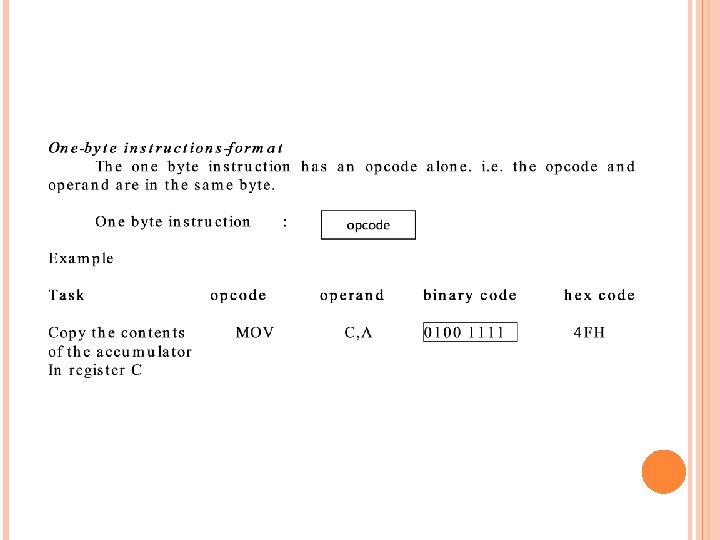
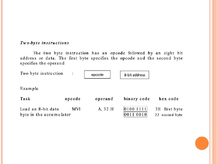
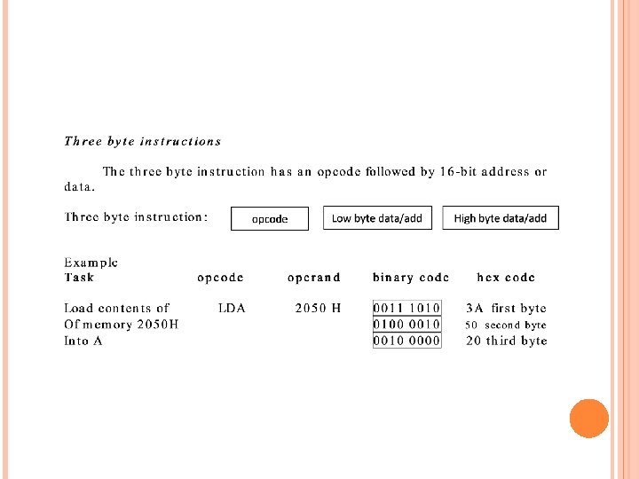
The 8085 instruction set is classified into the following three groups according to word size or byte size. 1 -byte instruction 2 -byte instruction 3 -byte instruction
DATA TRANSFER OR COPY INSTRUCTIONS One of the primary functions of the microprocessor is copying data, from a register (or I/O or memory) called the source, to another register (or I/O or memory) called the destination. The contents of the source are not transferred, but are copied into the destination register without modifying the contents of the source. Several instructions are used to copy data. This section is concerned with the following operations. MOV MVI OUT IN : move immediate : output to port copy a data byte load a data byte directly send a data byte to the output device : input from port read a data byte from an input device
The data transfer instructions move data between registers or between memory and registers. MOV - Move MVI - Move Immediate LDA - Load Accumulator Directly from Memory STA - Store Accumulator Directly in Memory LHLD - Load H & L Registers Directly from Memory SHLD - Store H & L Registers Directly in Memory An 'X' in the name of a data transfer instruction implies that it deals with a register pair (16 -bits); LXI - Load Register Pair with Immediate data LDAX - Load Accumulator from Address in Register Pair STAX - Store Accumulator in Address in Register Pair XCHG - Exchange H & L with D & E XTHL - Exchange Top of Stack with H & L
MOV RD, RS The content of source register (Rs) is copied to destination register (Rd). The registers Rd and Rs can be any one of the general purpose registers A, B, C, D, E, H and L. No flags are affected. The previous contents of the destination are replaced by the contents of the source.
MOV Rd, M (Rd) (M) The contents of memory (M) addressed by HL pair is moved to destination register (Rd). The register Rd can be any one of the general purpose registers A, B, C, D, E, H and L. No flags are affected.
MOV M, Rs (M) (Rs) The contents of source register is moved to the memory location addressed by HL pair. The register Rs can be any one of the general purpose registers A, B, C, D, E, H and L. No flags are affected.
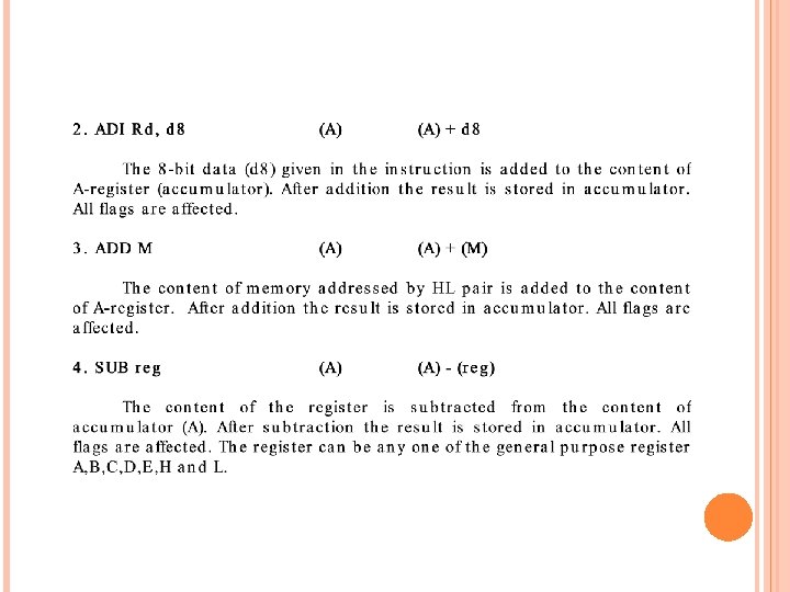
MVI Rd, d 8 (Rd) d 8 The 8 -bit data (d 8) given in the instruction is moved to destination register (Rd). The register Rd can be any one of the general purpose registers A, B, C, D, E, H and L. No flags are affected.
LDA addr 16 (A) (M) The content of the memory location whose address is given in the instruction is moved to accumulator. No flags are affected.
ARITHMETIC INSTRUCTIONS The 8085 microprocessor performs various arithmetic operations such as addition, subtraction, increment and decrement. These arithmetic operations have the following mnemonics. ADD : add the contents of a register ADI : add immediate add 8 -bit data SUB : subtract the contents of a register SUI : subtract immediate subtract 8 -bit data INR : increment increases the contents of register by 1 DCR : decrement decreases the contents of register by 1
ADDITION Any 8 -bit number or the contents of register or the contents of memory location can be added to the contents of accumulator. The result (sum) is stored in the accumulator No two other 8 -bit registers can be added directly Example : The contents of register B cannot be added directly to the contents of register C
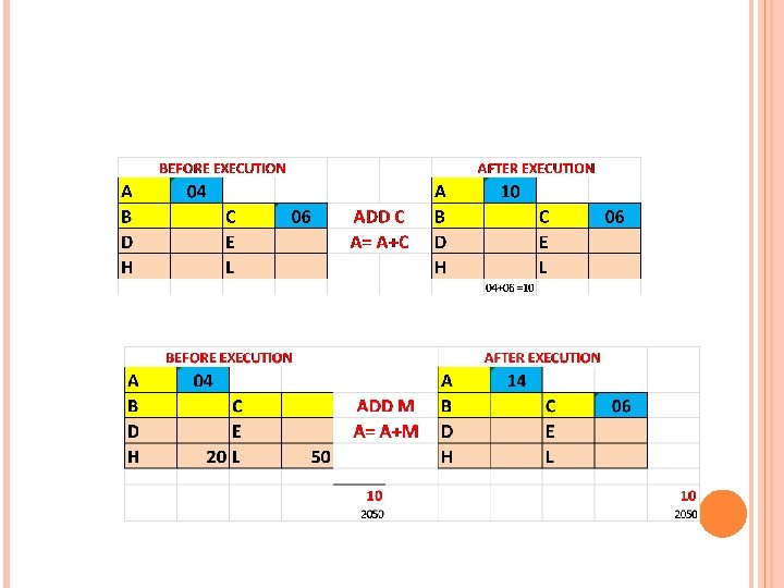
OPCODE ADD M OPERAND R DESCRIPTION Add register or memory to accumulator The contents of register or memory are added to the contents of accumulator The result is stored in accumulator If the operand is memory location, its address is specified by HL Pair Example: ADD C or ADD M
EXAMPLE ADD M (A)+(M) Or (A) + ((HL))
ARITHMETIC INSTRUCTIONS DAD Rp HL HL+Rp
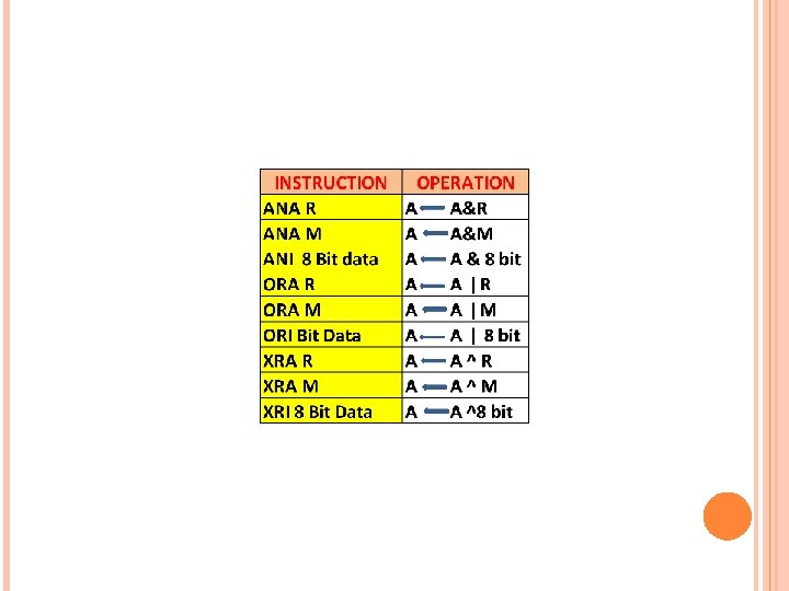
LOGICAL OPERATIONS
COMPARE, ROTATE INSTRUCTIONS INSTRUCTION OPERATION CMP R A-R CMP M A-M CPI 8 Bit data A- 8 bit data RLC RRC RAL RAR
CMP R The status of carry and zero flag after comparison are given below i) If (A) < (Reg) then the carry flag is set (CF=1) ii) If (A) > (Reg) then the carry flag is reset or cleared (CF=0) Iii) If (A) = (Reg) then the zero flag is set (ZF=1)
COMPARE REGISTER The content of the B-Register is compared with accumulator. The comparison is performed by subtracting the content of the B-Register from the content of the accumulator. The subtraction is performed in the ALU and the result is used to modify the flags and then discarded. The content of the accumulator and the B-Register are not altered
COMPARE REGISTER
COMPARE MEMORY The content of the memory addressed by HL pair is compared with accumulator. The comparison is performed by subtracting the content of the BRegister from the content of the accumulator. The subtraction is performed in the ALU and the result is used to modify the flags and then discarded. The content of the accumulator and the memory are not altered. All flags are affected by this instruction.
CMP M The status of carry and zero flag after comparison are given below i) If (A) < (M) then the carry flag is set (CF=1) ii) If (A) > (M) then the carry flag is reset or cleared (CF=0) Iii) If (A) = (M) then the zero flag is set (ZF=1)
Before Execution A 25 After Execution HL C 050 MEMORY 7 A CO 50 10 C 051 0111 1010 7 A 1000 0101 1' 1000 0110 2' A 15 HL C 050 CF 0 0010 0101 25 CF 1 PF 0 1000 0110 ADD PF 0 AF 0 1011 AB AF 0 ZF 0 SF 1 cc 1
CPI D 8 The 8 -bit data given in the instruction is compared with accumulator. The comparison is performed by subtracting the content of the B-Register from the content of the accumulator. The subtraction is performed in the ALU and the result is used to modify the flags and then discarded. The content of the accumulator and the memory are not altered. All flags are affected by this instruction.
CPI D 8 The status of carry and zero flag after comparison are given below i) If (A) < (d 8) then the carry flag is set (CF=1) ii) If (A) > (d 8) then the carry flag is reset or cleared (CF=0) Iii) If (A) = (d 8) then the zero flag is set (ZF=1)
RLC INSTRUCTIONS
RRC INSTRUCTIONS
RAL INSTRUCTIONS
RAR INSTRUCTIONS
OTHER INSTRUCTIONS CMA (Complement accumulator) The content of the accumulator is complemented. No flags are affected. STC (Set Carry) The carry flag is set to 1. Only carry flag is affected by this instruction CMC (Complement carry) The carry flag is complemented. Only the carry flag is affect this instruction.