80386 Multitasking Microcomputer systems are shared by several

80386 Multitasking • Microcomputer systems are shared by several computer operators, or users. • Each user commonly has a terminal that is connected to the computer and he is allowed to do his own work. • The computer in rotation allocates this time to all users. • This technique is known as time sharing and this is how nearly all computers support multiple user operations.
 Allows multiple users to use the same computer 2)")
• Time Sharing 1) Allows multiple users to use the same computer 2) Provides economical use of processing resources 3) Is invisible to the users 4) Can work for any number of users. • An operating system which co-ordinates the actions of a timeshare system such as this is referred to as a multi-user operating system. • The program or section of program for each user is referred to as a task, so a multi-user operating system implies multitasking.

Scheduling Methods for Multi-user Operating System • There are different approaches for implementing multi-user operating system. 1. Time-slice scheduling 2. Pre-emptive priority based scheduling.

Time-Slice Scheduling • There is a specific component of the operating system which determines when it time to switch from one task to another is called the scheduler, dispatcher or supervisor. • In time slice method in which CPU executes one task for small period of time (fraction of second) then switches to the next task. • After executing all tasks in a sequence, CPU returns to the first task. • The advantage of the time-slice approach in a multi-user system is that all users are serviced at approximately equal time intervals. • If number are more, time slices which each user gets, are less. • Thus each user's program takes more time to execute.

Pre-emptive-Priority based Scheduling • In this system, each task has given a priority number and higher priority tasks are allowed to interrupt lower priority tasks. • This means that when lower priority task is in execution, higher priority task can take control and after completion of higher priority task, it returns the control to the lower priority task. • This approach is suitable for most applications, because it allows the most important tasks to be done first.
 • It is a special type of segment, used to")
Task State Segment (TSS) • It is a special type of segment, used to manager the task. • The 80386 uses TSS like a scratch pad. It stores task environment in TSS. • TSS is not accessible to the general user program or program even at privilege level 0. The fields with in TSS are accessible to only 80386. • The fields of a TSS are divided into two sets : 1) Dynamic set 2) Static set
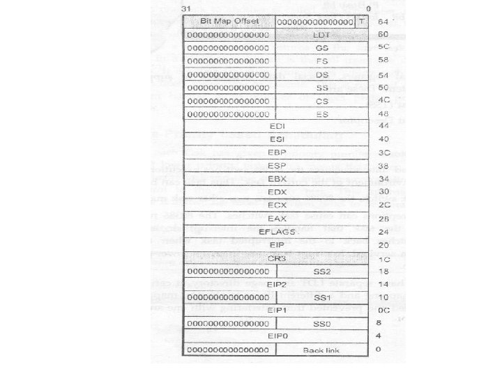

Dynamic Set • The 80386 updates dynamic set when it switches from one task to another task. • This set includes : 1) The general registers (EAX, EBX, ECX, EOX, ESP, EBP, ESI, EOI ) 2) The segment register (ES, SS, CS, ES, FS, GS) 3) The flag registers (EFLAGS) 4) The instruction pointer (EIP) 5) Back link.

Static Set • The 80386 only reads fields from this set. • This set includes: 1) The selector for the task's LDT 2) The register (PDBR) that contains the base address of the task's page directory 3) Pointers to the stacks for privilege levels 0 -2 4) The T-bit (debug trap bit) which causes the 80386 to raise a debug exception when a task switch occurs. 5) The I/O map offset. • Note: TSS static set saves the selector for the task's LDT. This means that TSS descriptors must appear only in the GDT.

• Task switching may change the privilege level changing the addressable domain of the program. • As rule says the privilege level of the stack segment must exactly match the Privilege level of the code segment at all times, the 80386 has to change stack when there is change in privilege level. • Due to this previous stack segment and pointer are abandoned, and a new stack is used that corresponds to the new privilege level. • When Control is returned to previous level, the previous stack is restored. • To store stack pointer and stack selector of the previous task fields ESP 0, ESP 1, ESP 2, SS 0, SS 1, SS 2 hold the stack segment pointers and stack selectors for privilege levels 0, 1 and 2.

TSS Descriptor • The limit field, however must have a value equal to or greater than 103 (104 -1), because 80386 requires minimum 104 bytes of storage in order to perform a context save. • A larger limit is permissible and it is required if an I/O permission map is present. The maximum limit for TSS is 4 GByte. • To access TSS descriptor, the procedure must have privilege level less than or equal to (numerically) privilege level specified by DPL field of the TSS descriptor. • Usually this access is restricted for only trusted software, whose privilege level is zero. • This can be done by setting DPL fields of TSS descriptor to zero.
 • The selector in the visible portion is used to specify")
Task Register (TR) • The selector in the visible portion is used to specify a TSS descriptor in the GDT and invisible portion is used to cache the base and limit values from the TSS descriptor.

• The 80386 gives two instructions to read and modify the visible portion of the task: 1) LTR (Load Task Register) 2) STR (Store Task Register) • LTR(Load Task Register): It loads the visible portion of the task register with the selector and invisible portion with information from the TSS descriptor selected by selector. • LTR is a privileged instruction. Thus it is executed only when CPL is zero. • STR (Store Task Register): It stores the visible portion of the task register in a general register or memory word. • STR is not a privilege instruction.

Task Gates and Task Gate Descriptor • Task gates, like call gates, are special system gates. • It has its own descriptor. A task gate descriptor does not define a memory segment but instead acts as an interface point between user code and a task state segment. It provides an indirect and protected reference to a TSS. • A task gate descriptor defines a selector to a TSS descriptor which uniquely identifies a task. • MAX (CPL, RPL) ≤ task gate DPL

Task Switching • The 80386 does task switching in any of four cases: 1. A long jump or call instruction contains a selector which refers to a TSS descriptor. This is the simplest method and can be easily implemented by the operating system kernel at the end of a time slice. 2. The selector in a long jump or call instruction refers to a task gate. In this case the selector for the destination TSS is in the task gate. This indirect method has advantages regarding privilege levels and protection.

3. The interrupt selector refers to a task gate in the interrupt descriptor table. The task gate contains the selector for the new TSS. If the access passes all the privilege level tests, the selector and descriptor for the interrupt task will be loaded into the task register. The nested task (NT) bit in the EFLAGs register will be set.

Task switch operation
")
Task Switching without Task Gate • Steps Involved in Task Switching (without Task Gate) : 1. Privilege Check: The current task is checked to see whether it is allowed to switch to the designated task. This is done by checking DPL of the designated TSS with RPL and CPL of the current task. If the DPL of the TSS descriptor is numerically greater than or equal to the maximum of CPL and the RPL of the selector then only the current task is allowed to switch to the designated task. 2. Limit and Present Bit Checking: The TSS descriptor for the designated task is checked for its limits and presence. 3. Saving the State of the Current Task: The 803860 X finds the base address of the current TSS cached in the task register. It copies the registers into the current TSS (EAX, ECX, EDX, EBX, ESP, EBP, ESI, EDI, ES, CS, OS, SS, FS, GS, the flag register and EIP). The EIP field of the TSS points to the instruction after the one that caused the task switch. The selector for the current task is saved as a back link selector in the new task.

4. Loading of Task Register: The visible portion of the task register is loaded with the selector of the designated task's TSS descriptor. This sets the TS (Task switch) bit in the Machine Status Word (MSW). The B Bit in the , new task's descriptor is marked busy. Then the corresponding task state descriptor is read from the GDT and loaded into the task register cache (hidden portion of task register). 5. Resuming Execution: Finally, 80386 starts execution of designated task, with the instruction pointed by the new contents of the code segment selector (CS) and instruction pointer (EIP).

Task Switching with Task Gate
 : 1. Privilege Check:")
• Steps Involved in Task Switching (using Task Gate) : 1. Privilege Check: When task gate is used, the DPL of the new TSS descriptor is not used for privilege checking. The DPL of the task gate is compared with the CPL and RPL of the gate selector. If the DPL of the task gate is numerically greater than or equal to the maximum of CPL and the RPL of the gate selector, the current task is allowed to switch to the designated/new task The remaining steps are similar excepts that for loading selector for TSS descriptor into TR task gate is referred instead of CALL or JMP instruction. • In case of exceptions, interrupts and IRET regardless of the DPL of the new task gate or TSS descriptor, the current task is allowed to switch to the new task

Nested Tasks Nested Task Switches • • Nested tasks act like subroutines. CALL instruction to task gate will nest tasks. Interrupt or exception to task gate will nest tasks. JMP instruction will not nest tasks. New TSS gets old TSS selector in Back Link field. New task gets nested task bit set in EFLAGS register. New task must return to old task with IRET instruction.
 • Maskable interrupts, which are routed via the INTR pin. •")
1. Interrupts (Hardware) • Maskable interrupts, which are routed via the INTR pin. • Non-Maskable interrupts, which are routed via the NMI (Non-Maskable Interrupt) pin. 2. Programmed/Software Interrupts: The instructions INTO, INT 3, INTn can trigger exceptions. These instructions are often called "Software Interrupts ", but the 80386 handles them as exceptions. .

3. Exceptions They are further classified as faults, traps, or aborts depending on the way they are reported, and whether or not restart of the instruction causing the exception is supported. • Faults: Faults are the exceptions that are detected and serviced before the execution of the faulting instruction. For example, in virtual memory system if page or segment referenced by processor is not present, the operating fetches the page or segment from disk using fault exception routine, and then 80386 restarts processing using referenced page or segment

• Traps: Traps are exceptions that are reported immediately after the execution of the instructions which causes the problem. User defined interrupts are the examples of traps. • Aborts: Aborts are exceptions which do not permit the precise location of the instruction causing the exception to be determined. Aborts are used to report severe errors, such a hardware error, or illegal values in the system tables.

Interrupt /Exception Processing • Each interrupt or exception is associated with a descriptor which gives the information about interrupt service routine. • These descriptors are stored in a special descriptor table called the interrupt descriptor table or IDT. This table can be located anywhere in memory. • The IDT is an array of 8 byte descriptors. The base address and limit for the interrupt descriptors table are loaded in to the interrupt descriptor table register (IDTR). • Because there are only 256 identifiers, the IDT need not contain more than 256 descriptors.

There are three types of descriptors can be used in the IDT. • Trap gate descriptor • Interrupt gate descriptor • Task gate descriptor. If any other type of descriptor is found in the IDT when an exception occurs , the 80386 generates a general protection fault.

Interrupt descriptor table and IDTR • IVT Vs IDT • In Real Mode, the IVT holds the addresses for different ISRs. The address of IVT is fixed it is from 0000 H to 03 FFH. • In protected mode, the interrupt descriptor table is relocatable address is given by IDTR

TASK and INTERRUPT Gates

Interrupt vectoring for procedures

• Trap Gate Vs Interrupt Gate • Trap gate operates exactly like an interrupt gate in all respect except one. When an exception vectors through a trap gate all flags remain exactly as they were when the exception occurred (No change in flags status). • When an exception vectors through an interrupt gate, the 80386 resets IF (Interrupt Flag) to disable further hardware interrupts, after it pushes the return address and EFLAGs but before it executes first instruction of the ISR.
- Slides: 31