80386 DX Processor CISC architecture full 32 bit

80386 -DX Processor • • CISC architecture full 32 bit version Microprocessor – 32 bit Data Bus(D 0 -D 31) – 32 bit Address Bus(A 2 -A 31, BE 0 -BE 3) – 32 bit register size(EAX, ABX, ESI…. . ) • Operating frequency (10 MHz-40 MHz) – We used 33 MHz processor operating at 12. 5 MHz

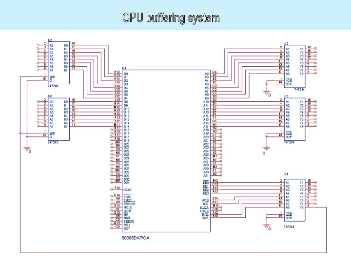
Buffering System 1. Needed to increase fan out 2. Used to protect Processor from unexpected signals 3. 74 f 244 try-state buffers for address bus and control signals, and 74 f 245 bydirectional try-state buffers for data busee

Control Signals • CLK 2: use 25 MHz to Operate processor at 12. 5 MHz • Reset: cause to begin executing software at physical address 0 x. FFFF 0 • Ready: used to generate wait states used 4 wait states for each Memory or IO assess (read /write)

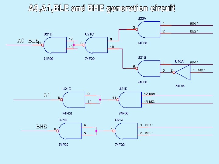
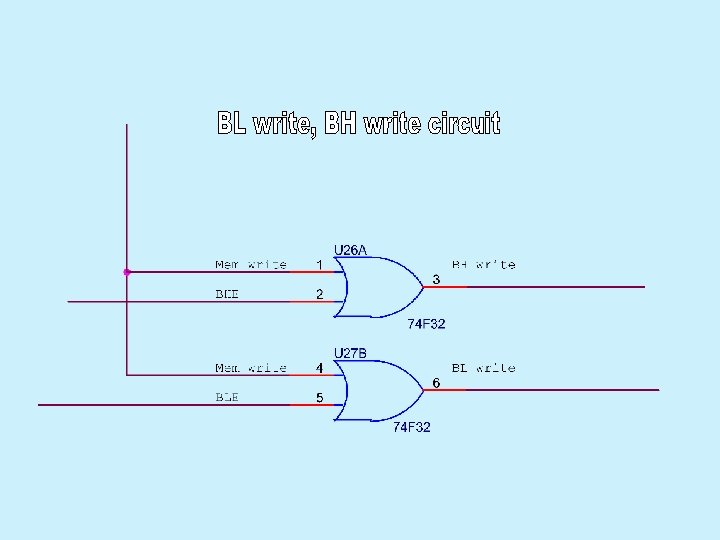
Control Signals • BS 16: used to select 16 bit data bus mode – • • We used 16 bit data bus. M/IO’, W/R’, D/C’, and ADS are used to control reading and writing on Memory and IO devices, and to generate Interrupt Acknowledgement. Other control lines are used to connect coprocessor (we didn’t use it), but have to be taken in mind.

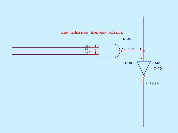
Memory Interface • real mode operating • 1 Mbyte memory size 0 x 00000 -0 x. FFFFF divided to 16 segments each of 64 Kbyte • used two chips 27 c 512 -150 ps 0 xe 0000 -0 x. FFFFF • and two chips 61 256 D-RAM (one segment )as shadowing for the rest of memory

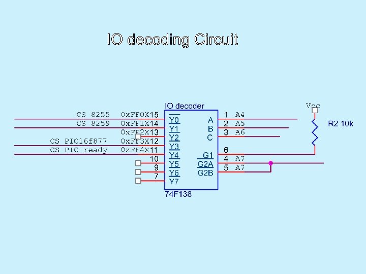
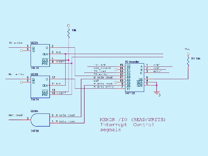
IO Interface 1. 80386 -Dx provides 16 bits for interfacing IO devices which means 64 k different IO addresses 2. Using decoding system to decode IO devices, a few IO addresses are needed, so Decoder 74 F 138 is an suitable.

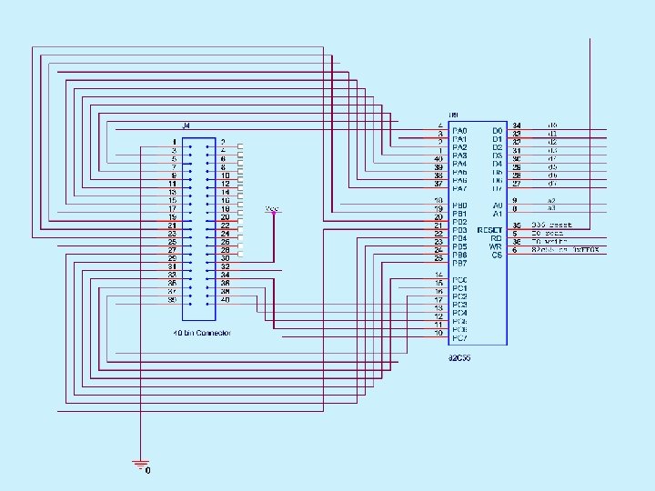
IO devices used 1. 82 c 55 A parallel peripheral interface 1. 2. 3. 4. IO address 0 x. FF 00 -Port A IO address 0 x. FF 04 -Port B IO address 0 x. FF 08 -Port C IO address 0 x. FF 0 C –Control Port

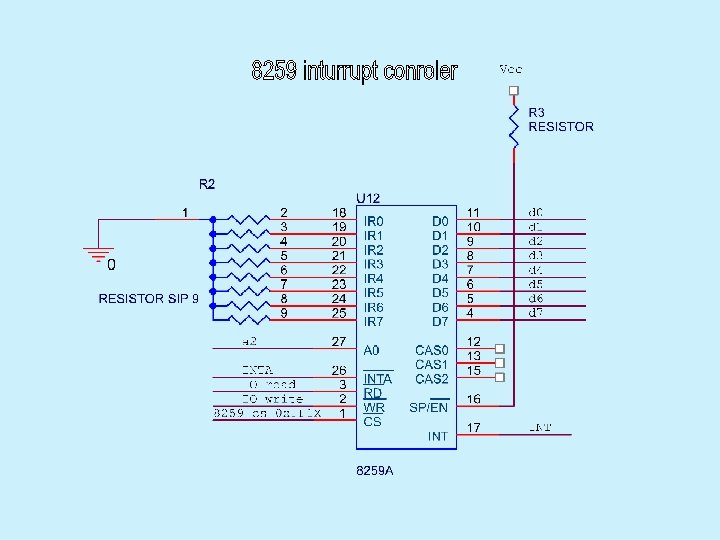
IO devices used • 8259 Interrupt Controller – IO Address 0 x. FF 10 -firs Port – IO Address 0 x. FF 14 -second Port
 • Using")
IO devices used • PIC 16 f 877 (running at 20 MHz) • Using PSP to connect PIC to the Microprocessor. • We used one output bit from the PIC to tell the processor if PIC is ready or not. • By reading IO port 0 x. FF 40 and testing least significant bit CPU will Know the state of the PIC.

PIC Commands Format • If the PIC is ready CPU can send Commands to the PIC. Each command consist of : – command type’ 4 bits’ – and data length’ 4 bits’ • followed by payload.

PIC Peripherals • PS-2 Keyboard • Serial Port • Graphical LCD (8 rows X 30 columns ) In addition to PSP to achieve communication between PIC and MP

Additional IO for future use • Real time Clock bq 3287 • 16 bit ISA bus.

Hardware Circuits

- Slides: 22