8 bit TimerCounter 2 with PWM and Asynchronous

8 -bit Timer/Counter 2 with PWM and Asynchronous Operation • Features – Single Compare unit Counter – Clear Timer on Compare Match (Auto Reload) – Glitch-free, Phase Correct Pulse Width Modulator (PWM) – Frequency Generator – 10 -bit Clock Prescaler – Overflow and Compare Match Interrupt Sources (TOV 2 and OCF 2) – Allows clocking from External 32 k. Hz Watch Crystal Independent of the I/O Clock
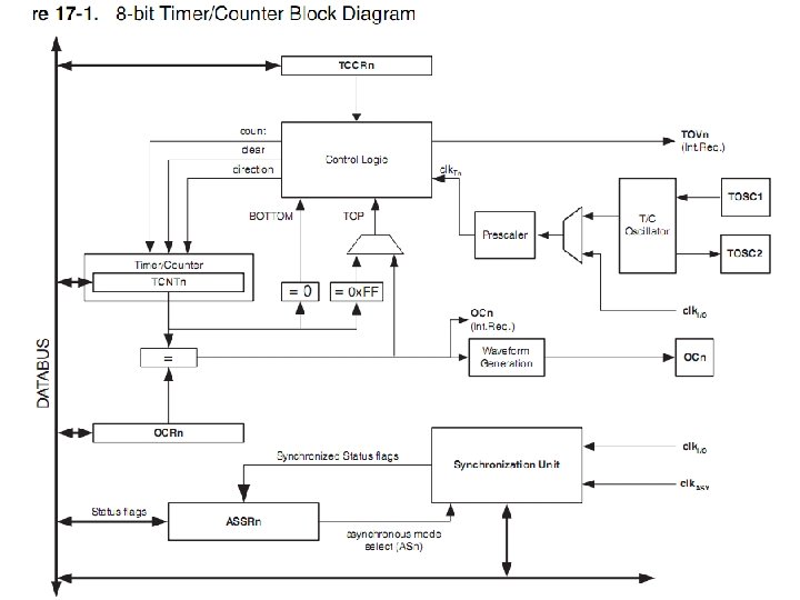

Registers • • TCCR 2 – Timer/Counter Control Register TCNT 2 – Timer/Counter Register OCR 2 – Output Compare Register ASSR – Asynchronous Status Register TIMSK – Timer/Counter Interrupt Mask Register TIFR – Timer/Counter Interrupt Flag Register SFIOR – Special Function IO Register

TCCR 2 – Timer/Counter Control Register • Bit 7 – FOC 2: Force Output Compare • Bit 3, 6 – WGM 2[1: 0]: Waveform Generation Mode • Bit 5: 4 – COM 21: 0: Compare Match Output Mode • Bit 2: 0 – CS 22: 0: Clock Select

ASSR – Asynchronous Status Register • Bit 3 – AS 2: Asynchronous Timer/Counter 2 • Bit 2 – TCN 2 UB: Timer/Counter 2 Update Busy • Bit 1 – OCR 2 UB: Output Compare Register 2 Update Busy • Bit 0 – TCR 2 UB: Timer/Counter Control Register 2 Update Busy

Bit 3 – AS 2: Asynchronous Timer/Counter 2 • When AS 2 is written to zero, Timer/Counter 2 is clocked from the I/O clock, clk. I/O. • When AS 2 is written to one, Timer/Counter 2 is clocked from a Crystal Oscillator connected to the Timer Oscillator 1 (TOSC 1) pin. • When the value of AS 2 is changed, the contents of TCNT 2, OCR 2, and TCCR 2 might be corrupted.

• Bit 2 – TCN 2 UB: Timer/Counter 2 Update Busy • When Timer/Counter 2 operates asynchronously and TCNT 2 is written, this bit becomes set. • When TCNT 2 has been updated from the temporary storage register, this bit is cleared by hardware. • A logical zero in this bit indicates that TCNT 2 is ready to be updated with a new value.

• Bit 1 – OCR 2 UB: Output Compare Register 2 Update Busy • When Timer/Counter 2 operates asynchronously and OCR 2 is written, this bit becomes set. • When OCR 2 has been updated from the temporary storage register, this bit is cleared by hardware. • A logical zero in this bit indicates that OCR 2 is ready to be updated with a new value.

• Bit 0 – TCR 2 UB: Timer/Counter Control Register 2 Update Busy • When Timer/Counter 2 operates asynchronously and TCCR 2 is written, this bit becomes set. • When TCCR 2 has been updated from the temporary storage register, this bit is cleared by hardware. • A logical zero in this bit indicates that TCCR 2 is ready to be updated with a new value. • If a write is performed to any of the three Timer/Counter 2 Registers while its update busy flag is set, the updated value might get corrupted and cause an unintentional interrupt to occur. • The mechanisms for reading TCNT 2, OCR 2, and TCCR 2 are different. • When reading TCNT 2, the actual timer value is read. When reading OCR 2 or TCCR 2, the value in the temporary storage register is read.

TIMSK – Timer/Counter Interrupt Mask Register • Bit 7 – OCIE 2: Timer/Counter 2 Output Compare Match Interrupt Enable • Bit 6 – TOIE 2: Timer/Counter 2 Overflow Interrupt Enable

TIFR – Timer/Counter Interrupt Flag Register • Bit 7 – OCF 2: Output Compare Flag 2 • Bit 6 – TOV 2: Timer/Counter 2 Overflow Flag

Bit 7 – OCF 2: Output Compare Flag 2 • The OCF 2 bit is set (one) when a compare match occurs between the Timer/Counter 2 and the data in OCR 2 – Output Compare Register 2. OCF 2 is cleared by hardware when executing the corresponding interrupt handling vector. • Alternatively, OCF 2 is cleared by writing a logic one to the flag. • When the I-bit in SREG, OCIE 2 (Timer/Counter 2 Compare match Interrupt Enable), and OCF 2 are set (one), the Timer/Counter 2 Compare match Interrupt is executed

Bit 6 – TOV 2: Timer/Counter 2 Overflow Flag • The TOV 2 bit is set (one) when an overflow occurs in Timer/Counter 2. TOV 2 is cleared by hardware when executing the corresponding interrupt handling vector. • Alternatively, TOV 2 is cleared by writing a logic one to the flag. • When the SREG I-bit, TOIE 2 (Timer/Counter 2 Overflow Interrupt Enable), and TOV 2 are set (one), the Timer/Counter 2 Overflow interrupt is executed. • In PWM mode, this bit is set when Timer/Counter 2 changes counting direction at $00.

SFIOR – Special Function IO Register • Bit 1 – PSR 2: Prescaler Reset Timer/Counter 2 – When this bit is written to one, the Timer/Counter 2 prescaler will be reset. – The bit will be cleared by hardware after the operation is performed. – Writing a zero to this bit will have no effect. – This bit will always be read as zero if Timer/Counter 2 is clocked by the internal CPU clock. – If this bit is written when Timer/Counter 2 is operating in asynchronous mode, the bit will remain one until the prescaler has been reset.
- Slides: 14