7 segment Display Arrangment of segment 7 segment


 is a device that allows digital information from several")


 basically reversed the multiplexing function • It takes a")


- Slides: 74
7 segment Display • Arrangment of segment
7 segment Display • Display of decimal digits with 7 -segment device
7 segment Display • Arrangement of 7 -segment LED displays
7 segment Display • Active segments for each decimal digit
7 segment Display • Block diagram of 7 -segment logic and display
7 segment Display • Truth table for 7 -segment logic
PULSE WAVEFORM • The operation of any gate is the same regardless of whether its inputs are pulsed or constant levels • The nature of the inputs (pulsed or constant-levels) does not alter the truth table of a circuit
PULSE WAVEFORM
PULSE WAVEFORM
PULSE WAVEFORM
PULSE WAVEFORM
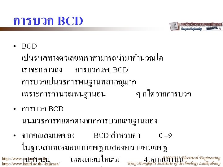
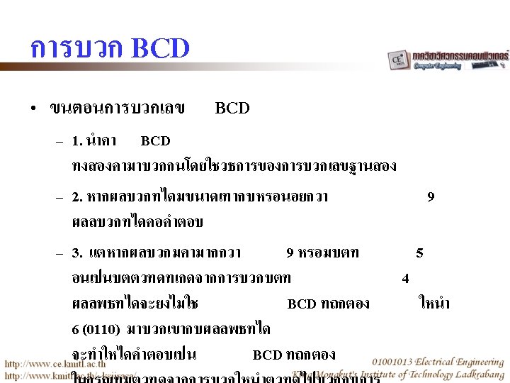
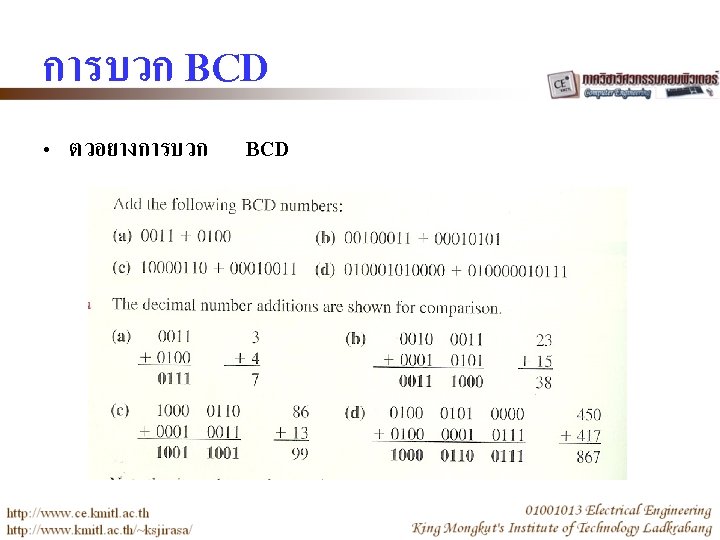
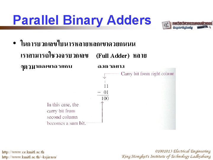
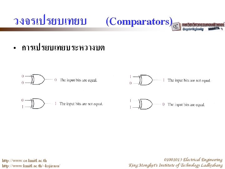
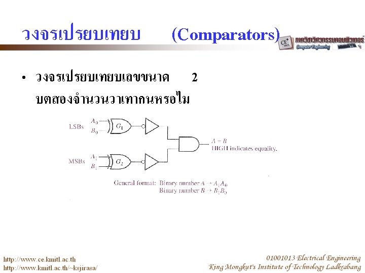
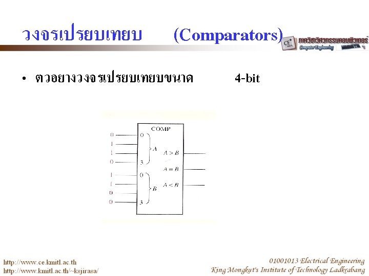
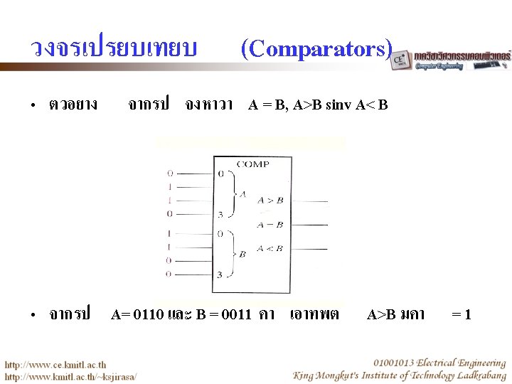
Parallel Binary Adders • วงจร
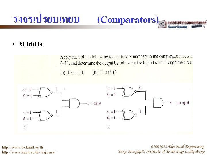
Parallel Binary Adders • ตวอยาง
Parallel Binary Adders • 4 -bit parallel Binary Adder
Adder Expansion • Cascading of two 4 -bit adders to form an 8 -bit adders
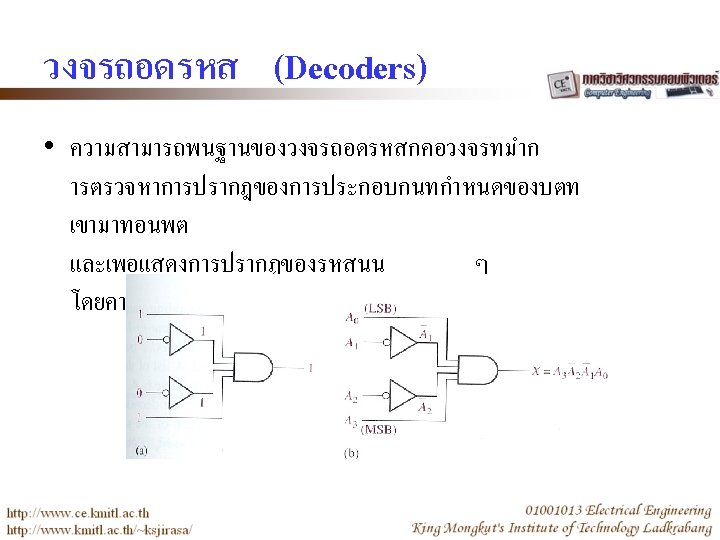
1011 decoder
BCD to Decimal Decoder • The BCD to Decimal Decoder converts each BCD code (8421 BCD) into one of ten possible decimal digit indications • It is frequently referred as a 4 -line-to-10 line decoder or a 1 -of-10 -decoder
BCD to Decimal Decoder • Truth table
BCD to 7 -segment Decoder • The BCD to 7 -segment decoder accepts the BCD code on its inputs and provides outputs to drive 7 -segment display devices to produce a decimal readout
BCD to 7 -segment Decoder • Logic diagram for 7 -segment decoder
BCD to 7 -segment Decoder • Pin diagram and logic symbol for the 74 LS 47 IC
ENCODER • An encoder is a combinational logic circuit that essential performs a “reverse” decoder function. • It accepts an active level on one of its inputs representing a digit, such as a decimal or octal digit, and convert it to a coded output such as a BCD or Binary
Decimal-to-BCD Encoder • Logic symbol for a decimal-to-BCD encoder
Decimal-to-BCD Encoder • Truth table
Decimal-to-BCD Encoder • Logic diagram of a decimal-to-BCD encoder
Decimal-to-BCD Encoder • Pin diagram and logic symbol for the 74 HC 147 IC
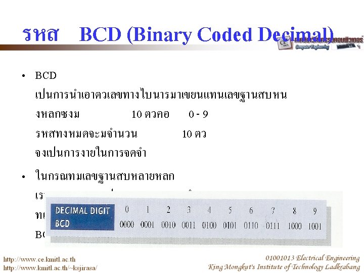
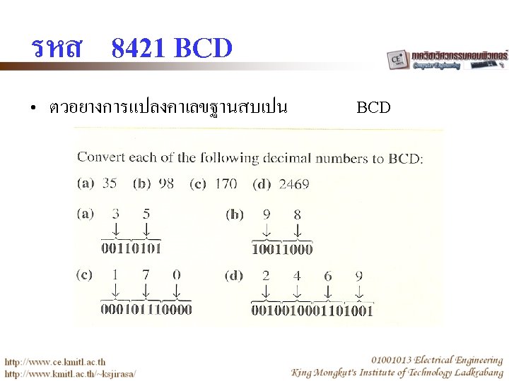
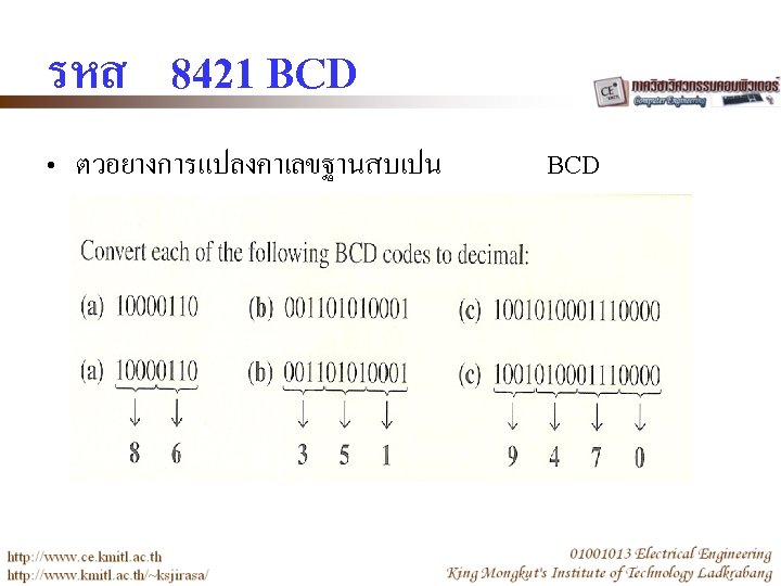
Code Converter • A combinational logic circuits to convert from one code to another – BDC-to-Binary Conversion • The value, or weight, of each bit in the BCD number is represented by a binary number • All of the binary representations of the weights of bits that are 1 s in the BCD number are added • The result of this addition is the binary equivalent of the BCD number
Code Converter • BDC-to-Binary Conversion
Code Converter • BDC-to-Binary Conversion
MULTIPLEXER • A multiplexer (MUX) is a device that allows digital information from several sources to be routed onto a single line for transmission over that line to a common destination • The basic multiplexer has several data-input lines and a single output line. It also has dataselect inputs, which permit digital data on any one of the inputs to be switched to the output line
MULTIPLEXER • Logic symbol for a 1 -to-4 data selector/multiplexer
MULTIPLEXER • Data selection for a 1 -to-4 -multiplexer
MULTIPLEXER • Logic diagram for a 4 -input multiplexer
DEMULTIPLEXER • A demultiplexer (DEMUX) basically reversed the multiplexing function • It takes a digital information from one line and distributed it to a given number of output lines • Also known as a data distributor
DEMULTIPLEXER • A 1 -to-4 line demultiplexer
DEMULTIPLEXER • Output waveform on D 0 through D 3
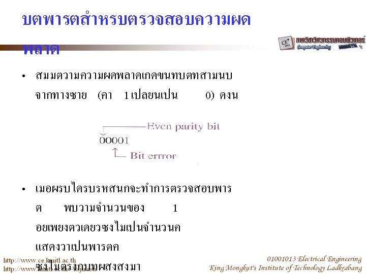
PARITY GENERATOR/CHECKER • Error can occur as a digital codes are being transferred from one point to another within a digital system or while codes are being transmitted from one system to another • The error take the form of undesired in the bits that make up the code information; that is a 1 can change to a 0, or a 0 to a 1 because of the component malfunction or electrical noise
PARITY GENERATOR/CHECKER • In most digital systems, the probability that even a single bit error will occur is very small, and the likelihood that more than one will occur is even smaller • Nevertheless, when an error occurs undetected, it can cause serious problems in a digital system
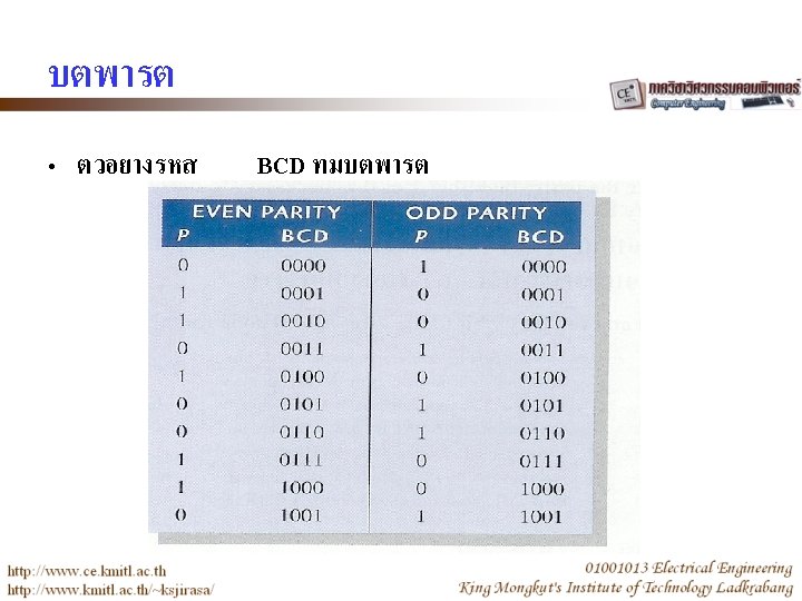
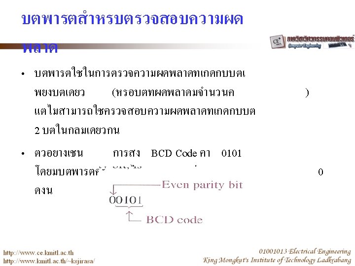
PARITY GENERATOR/CHECKER • Basic parity logic – 1 parity bit indicates if the number of 1 s in a code is even or odd for the purpose of error detection – In order to check for or to generate the proper parity in a given code, a basic principle can be used • The sum (disregarding carries) of an even number of 1 s is always 0, and the sum of an odd number of 1 s is always 1
PARITY GENERATOR/CHECKER • Basic parity logic – Therefore to determine if a given code has even parity or odd parity, all the bits in that code are summed
PARITY GENERATOR/CHECKER • A 9 -bit parity generator/checker