67535 Computer Games Programming Week 4 textures Tutorial

 per fragment, not per vertex Solution:")


![Texture addressing mode What if texture coordinates don’t stay in range [0 1]? Texture](https://slidetodoc.com/presentation_image/3ca4aedcd0aae0975153090e18058f65/image-11.jpg "Texture addressing mode What if texture coordinates don’t stay in range [0 1]? Texture")


")


 • Aka Texture space or polygon face space – T tangent,")


 Using height-map and angle from surface to viewer to displace the")


- Slides: 36
67535: Computer Games Programming Week 4: – textures – Tutorial: textures; . obj files
Texture mapping Motivation: adjusting colour (and other parameters) per fragment, not per vertex Solution: texturing each face from an image
UV coordinates 0. 6, 0. 1 0, 0 1, 0 0. 45, 0. 5 0. 9, 0. 8 0. 1, 0. 9 0, 1 1, 1
UV interpolation X V
Problems with textures
Min/Mag Filters • Nearest point sampling: maps a texel onto nearest screen pixel • Linear filtering: averages 2*2 texels surrounding a given screen pixel • Gaussian filtering: weighs 2*2 texels surrounding a given screen pixel with bell-curve coefficients • Anisotropic Filtering: accounts for distortion when angle between view vector and polygon normal is wide (Max. Anisotropy parameter determines the quality of filtering)
Anisotropic Filters
Optimisation: Mipmaps From Latin multo in parvo: a lot in small place Improve the look and reduce the data size If hardware supports mipmaps, a mipmap chain will be generated automatically when a texture is loaded from file. The best mipmap that matches screen triangle based on specified filter is automatically selected
Anisotropic mipmapping
Mipmap filter states • NONE: Disable mipmapping • POINT: use mipmap level closest in size to screen triangle, then filter that level based on specified min and mag filters • LINEAR: take 2 mipmap levels that are closest in size to screen triangle, filter each level with the min-mag filters specified and combine linearly
Texture addressing mode What if texture coordinates don’t stay in range [0 1]? Texture addressing mode controls what happens to texture coordinates that are outside the [0. 0, 1. 0] range
• Wrap: repeats the texture on every integer junction. This is the default mode. • Mirror: mirrors the texture at every integer boundary. • Border: texture coordinates outside the range [0. 0, 1. 0] are set to the border colour. • Clamp: texture coordinates outside the range [0. 0, 1. 0] are set to the texture colour at 0. 0 or 1. 0, respectively. • …and others
Fragment shaders and textures Fragment shaders receive sets of texture coordinates and combine values sampled from textures The trick is to use textures as generic per-fragment data structures, not just for colour
Case study 1: reflexion mapping
Skybox An infinitely faraway sphere with a cube map texture Cube map: special texture data structure; six square 2 D textures on the faces of a cube; each face is a scene from a 90° field of view camera placed at the origin looking along an axis
Cube Map coordinates The Cube map is accessed via vectors expressed as 3 D texture coordinates ( S, T, R ). +T, +Y +S, +X -R, -Z The greatest magnitude component, S, T or R, is used to select the cube face. The other 2 components are used to select a texel from that face.
Reflections of Skybox angle of incidence = angle of reflection Vertex shader outputs a texture coordinate which is the “reflection” of the vector from camera to object Fragment shader maps that texture coordinate into a skybox
Refractions of Skybox Same as reflection, only instead of reflecting, the view vector is changed according to Snell’s law: ni sin (i) = nr sin (r) Where i is angle of incidence, r is angle of refraction, ni and nr are the refractive indices of the two mediums Sample refractive indices: Air = 1. 00; water = 1. 33; Diamond = 2. 42
Glass Linear combination of reflexion and refraction based on angle from camera
Limitations
Case study 2: bump mapping
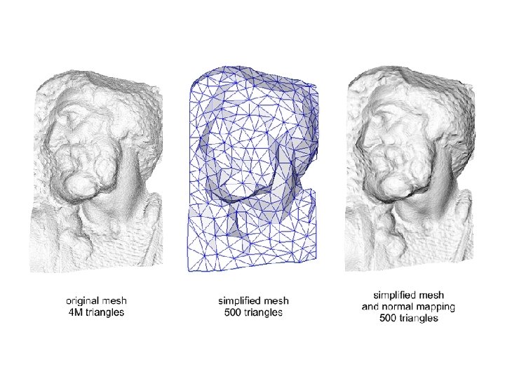
Motivation Phong lighting is good for smooth objects – What about high frequency details such as crevices, bumps or scratches? Increasing poly count is costly – Makes no sense for large distances when high detail level is not required Need different level of detail at different distances – mip-mapping, but for detail, not colour
General idea Separate objects into low-poly shape and variable levels of detail Geometry (polygons) encodes shape ‘Texture’ encodes fine detail – not colour
Displacement mapping Modifying the mesh – Requires tessellation or on-the -fly mesh generation capabilities – Accurate but slow
Bump mapping Perturb the surface normal used in the lighting calculations – Real surface geometry is unchanged – But there is an appearance of bumpiness Simplest to implement and compute Does not affect silhouette, occlusion, shadows etc
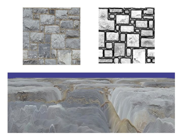
Implementations Blinn bump mapping – Texture encodes height of texel above the face – Fragment normal is calculated at runtime Normal mapping – Texture encodes dn - normal vector displacement relative to face normal – pre-computed from height map at design stage
Tangent space (TBN) • Aka Texture space or polygon face space – T tangent, tangent to surface – B binormal, ‘the other tangent to surface’ – N normal, normal to surface
Vertex shader 1. 2. 3. Compute TBN-base for each triangle of mesh Transform the light vector from object space to tangent space Output light vector in tangent space Fragment shader 1. Use light vector and normal displacement (from texture) to calculate shading
Limitations
Parallax mapping (2001) Using height-map and angle from surface to viewer to displace the texture coordinates – Simple and fast, yet almost as good-looking as displacement mapping – Improvements for occlusions and self-shadows
No parallax mapping
With Parallax mapping
Relief mapping Several layers of heightmaps and normals stored for each texel Describes ‘mesostructure’
Tutorial Assignment 2 • Deadline: April 10 th, 10 am – Simulate walking down endless dark corridor with a simple geometry and rolling texture – Implement an attenuated directional light source (spotlight) – Optional: • Separate controls of movement and spotlight • Flickering spotlight • Random objects in the corridor