
61 C In the News Initially when the

- Slides: 26
61 C In the News Initially, when the i. Phone 4 S went on sale Oct. 14, many users couldn't get Siri to work because so many people were trying at the same time. Siri needs to go through Apple's cloud-based servers to work, and Siri's popularity caused a bit of a traffic jam. 3/7/2021 Fall 2011 -- Lecture #31 1
CS 61 C: Great Ideas in Computer Architecture (Machine Structures) Lecture 31: Pipeline Parallelism 2 Instructors: Mike Franklin Dan Garcia http: //inst. eecs. Berkeley. edu/~cs 61 c/fa 11 3/7/2021 Fall 2011 -- Lecture #31 2
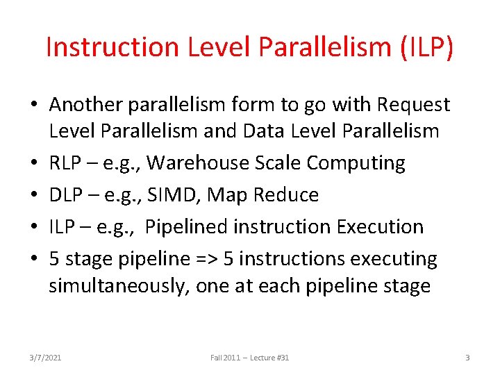
Instruction Level Parallelism (ILP) • Another parallelism form to go with Request Level Parallelism and Data Level Parallelism • RLP – e. g. , Warehouse Scale Computing • DLP – e. g. , SIMD, Map Reduce • ILP – e. g. , Pipelined instruction Execution • 5 stage pipeline => 5 instructions executing simultaneously, one at each pipeline stage 3/7/2021 Fall 2011 -- Lecture #31 3
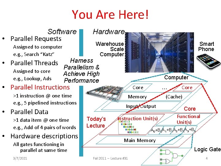
You Are Here! Software • Parallel Requests Assigned to computer e. g. , Search “Katz” • Parallel Threads Assigned to core e. g. , Lookup, Ads Hardware Smart Phone Warehouse Scale Computer Harness Parallelism & Achieve High Performance Computer • Parallel Instructions >1 instruction @ one time e. g. , 5 pipelined instructions • Parallel Data >1 data item @ one time e. g. , Add of 4 pairs of words • Hardware descriptions All gates functioning in parallel at same time 3/7/2021 Core … Memory (Cache) Input/Output Today’s Lecture Core Instruction Unit(s) Core Functional Unit(s) A 0+B 0 A 1+B 1 A 2+B 2 A 3+B 3 Main Memory Logic Gates Fall 2011 -- Lecture #31 4
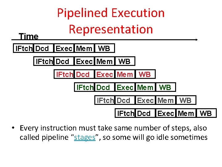
Time Pipelined Execution Representation IFtch Dcd Exec Mem WB IFtch Dcd Exec Mem WB • Every instruction must take same number of steps, also called pipeline “stages”, so some will go idle sometimes
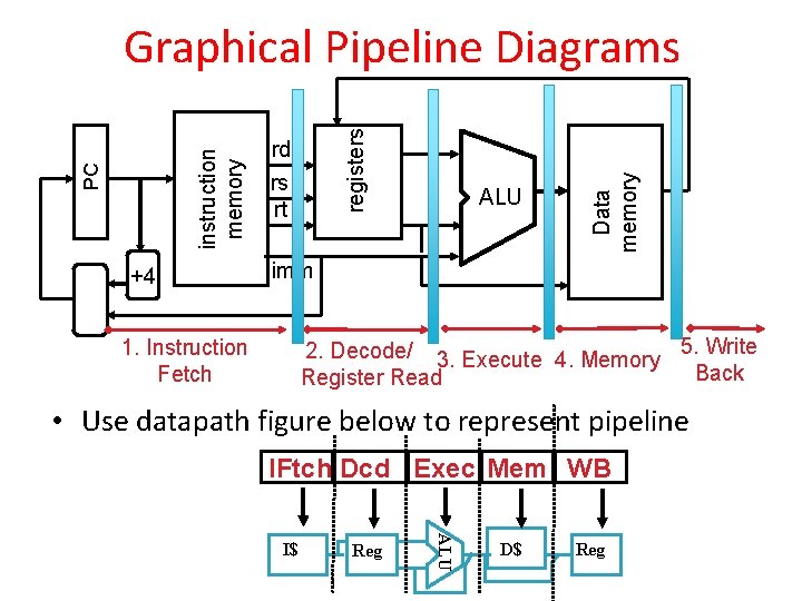
+4 rd rs rt ALU Data memory registers PC instruction memory Graphical Pipeline Diagrams imm 2. Decode/ 3. Execute 4. Memory 5. Write Back Register Read 1. Instruction Fetch • Use datapath figure below to represent pipeline IFtch Dcd Exec Mem WB Reg ALU I$ D$ Reg
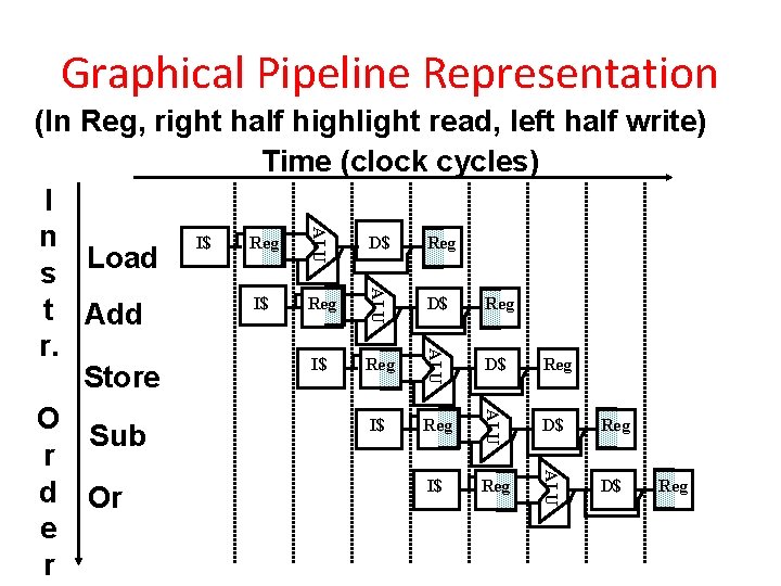
Graphical Pipeline Representation ALU (In Reg, right half highlight read, left half write) Time (clock cycles) I n I$ D$ Reg Load s I$ D$ Reg t Add r. I$ D$ Reg Store O I$ D$ Reg Sub r I$ D$ Reg d Or e r ALU ALU
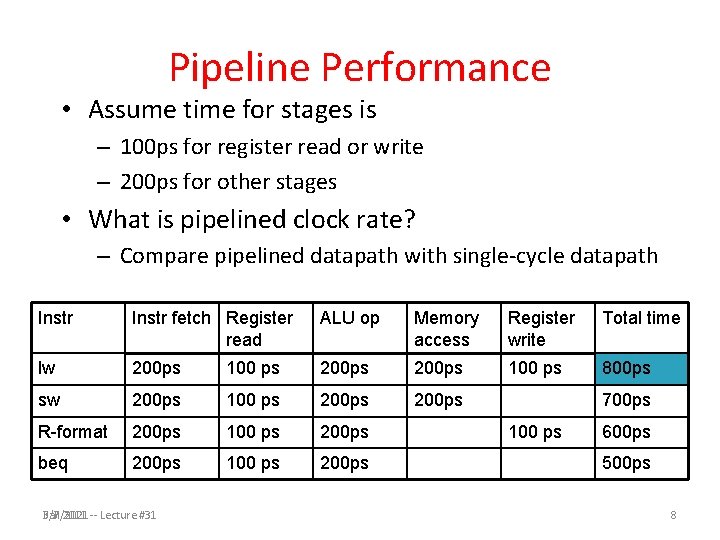
Pipeline Performance • Assume time for stages is – 100 ps for register read or write – 200 ps for other stages • What is pipelined clock rate? – Compare pipelined datapath with single-cycle datapath Instr fetch Register read ALU op Memory access Register write Total time lw 200 ps 100 ps 800 ps sw 200 ps 100 ps 200 ps R-format 200 ps 100 ps 200 ps beq 200 ps 100 ps 200 ps Fall 2011 -- Lecture #31 3/7/2021 700 ps 100 ps 600 ps 500 ps 8
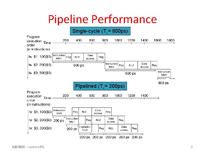
Pipeline Performance Single-cycle (Tc= 800 ps) Pipelined (Tc= 200 ps) Fall 2011 -- Lecture #31 3/7/2021 9
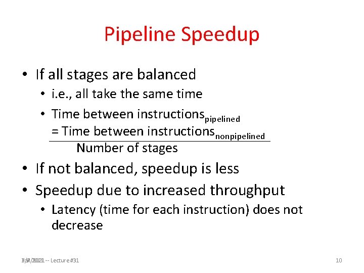
Pipeline Speedup • If all stages are balanced • i. e. , all take the same time • Time between instructionspipelined = Time between instructionsnonpipelined Number of stages • If not balanced, speedup is less • Speedup due to increased throughput • Latency (time for each instruction) does not decrease Fall 2011 -- Lecture #31 3/7/2021 10
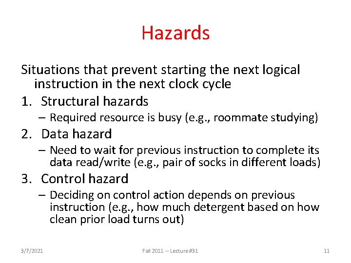
Hazards Situations that prevent starting the next logical instruction in the next clock cycle 1. Structural hazards – Required resource is busy (e. g. , roommate studying) 2. Data hazard – Need to wait for previous instruction to complete its data read/write (e. g. , pair of socks in different loads) 3. Control hazard – Deciding on control action depends on previous instruction (e. g. , how much detergent based on how clean prior load turns out) 3/7/2021 Fall 2011 -- Lecture #31 11
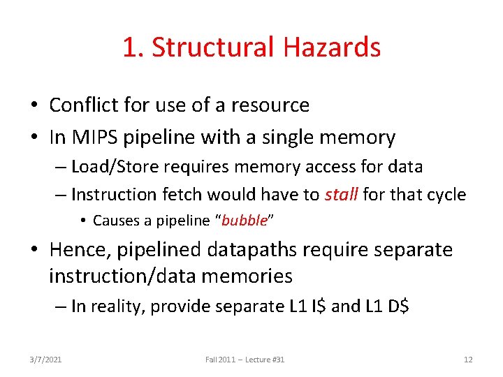
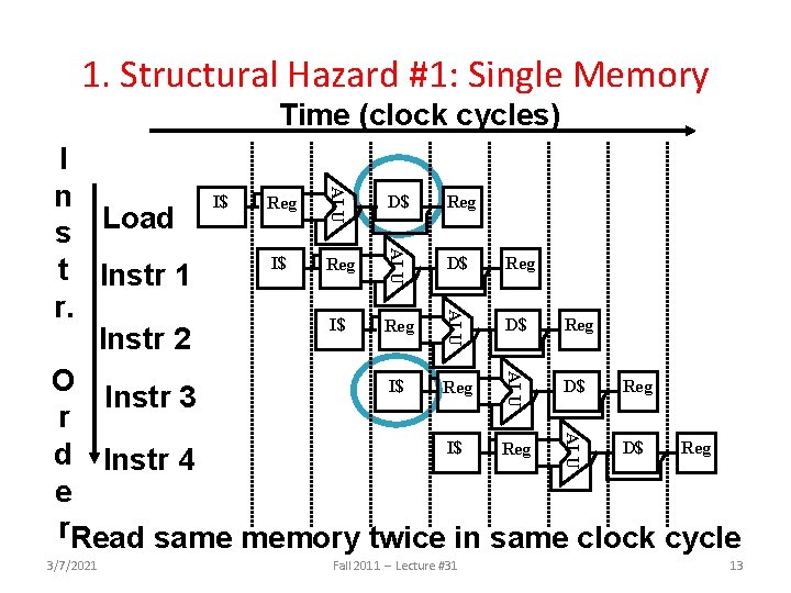
1. Structural Hazards • Conflict for use of a resource • In MIPS pipeline with a single memory – Load/Store requires memory access for data – Instruction fetch would have to stall for that cycle • Causes a pipeline “bubble” • Hence, pipelined datapaths require separate instruction/data memories – In reality, provide separate L 1 I$ and L 1 D$ 3/7/2021 Fall 2011 -- Lecture #31 12
1. Structural Hazard #1: Single Memory Time (clock cycles) ALU I n I$ D$ Reg Load s I$ D$ Reg t Instr 1 r. I$ D$ Reg Instr 2 O I$ D$ Reg Instr 3 r I$ D$ Reg d Instr 4 e r. Read same memory twice in same clock cycle ALU ALU 3/7/2021 Fall 2011 -- Lecture #31 13
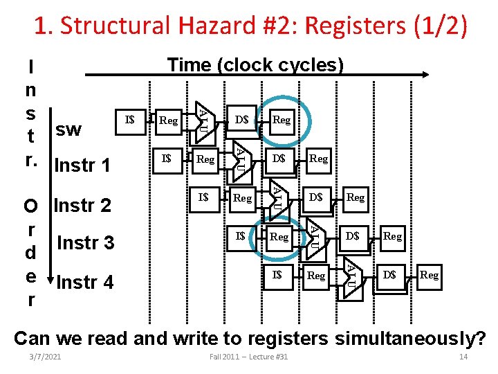
1. Structural Hazard #2: Registers (1/2) Reg D$ Reg I$ Reg ALU I$ D$ ALU Reg ALU I$ ALU O Instr 2 r Instr 3 d e Instr 4 r Time (clock cycles) ALU I n s t sw r. Instr 1 D$ Reg Can we read and write to registers simultaneously? 3/7/2021 Fall 2011 -- Lecture #31 14
1. Structural Hazard #2: Registers (2/2) • Two different solutions have been used: 1) Reg. File access is VERY fast: takes less than half the time of ALU stage • Write to Registers during first half of each clock cycle • Read from Registers during second half of each clock cycle 2) Build Reg. File with independent read and write ports • Result: can perform Read and Write during same clock cycle 3/7/2021 Fall 2011 -- Lecture #31 15
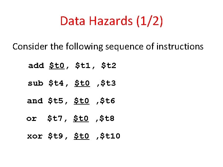
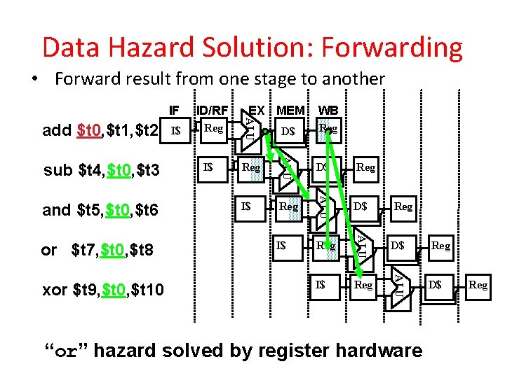
Data Hazards (1/2) Consider the following sequence of instructions add $t 0, $t 1, $t 2 sub $t 4, $t 0 , $t 3 and $t 5, $t 0 , $t 6 or $t 7, $t 0 , $t 8 xor $t 9, $t 0 , $t 10
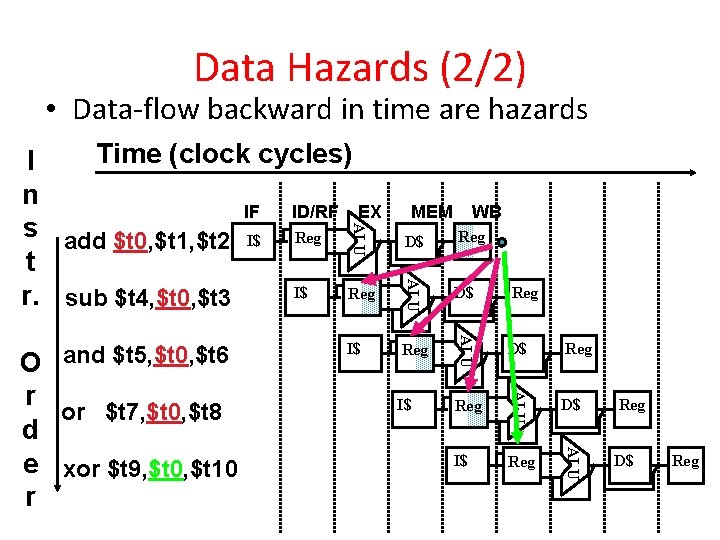
Data Hazards (2/2) • Data-flow backward in time are hazards D$ Reg Reg D$ Reg I$ Reg ALU r or $t 7, $t 0, $t 8 d e xor $t 9, $t 0, $t 10 r I$ WB ALU O and $t 5, $t 0, $t 6 MEM ALU Time (clock cycles) I n IF ID/RF EX s add $t 0, $t 1, $t 2 I$ Reg t I$ Reg r. sub $t 4, $t 0, $t 3 D$ Reg
Data Hazard Solution: Forwarding • Forward result from one stage to another Reg D$ Reg I$ Reg ALU xor $t 9, $t 0, $t 10 I$ D$ ALU or $t 7, $t 0, $t 8 Reg WB ALU and $t 5, $t 0, $t 6 I$ EX MEM ALU sub $t 4, $t 0, $t 3 ID/RF ALU add $t 0, $t 1, $t 2 IF D$ “or” hazard solved by register hardware Reg
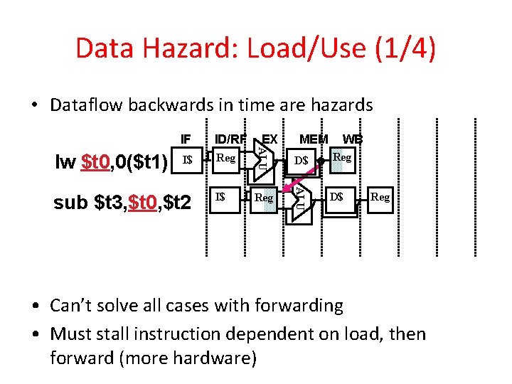
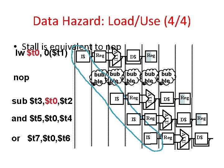
Data Hazard: Load/Use (1/4) • Dataflow backwards in time are hazards I$ Reg I$ sub $t 3, $t 0, $t 2 EX MEM WB D$ Reg ALU ID/RF ALU lw $t 0, 0($t 1) IF D$ Reg • Can’t solve all cases with forwarding • Must stall instruction dependent on load, then forward (more hardware)
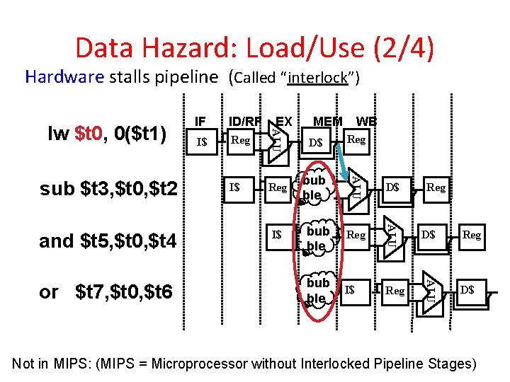
Data Hazard: Load/Use (2/4) Hardware stalls pipeline (Called “interlock”) I$ WB D$ Reg bub ble I$ D$ bub ble Reg D$ bub ble I$ Reg ALU or $t 7, $t 0, $t 6 Reg MEM ALU and $t 5, $t 0, $t 4 I$ EX ALU sub $t 3, $t 0, $t 2 ID/RF ALU lw $t 0, 0($t 1) IF Reg D$ Not in MIPS: (MIPS = Microprocessor without Interlocked Pipeline Stages)
Data Hazard: Load/Use (3/4) • Instruction slot after a load is called “load delay slot” • If that instruction uses the result of the load, then the hardware interlock will stall it for one cycle. • Alternative: If the compiler puts an unrelated instruction in that slot, then no stall • Letting the hardware stall the instruction in the delay slot is equivalent to putting a nop in the slot (except the latter uses more code space)
Data Hazard: Load/Use (4/4) and $t 5, $t 0, $t 4 or $t 7, $t 0, $t 6 Reg bub ble bub ble I$ Reg D$ Reg I$ Reg ALU sub $t 3, $t 0, $t 2 D$ ALU nop I$ ALU lw $t 0, 0($t 1) ALU • Stall is equivalent to nop D$ Reg
Pipelining and ISA Design • MIPS Instruction Set designed for pipelining • All instructions are 32 -bits – Easier to fetch and decode in one cycle – x 86: 1 - to 17 -byte instructions (x 86 HW actually translates to internal RISC instructions!) • Few and regular instruction formats, 2 source register fields always in same place – Can decode and read registers in one step • Memory operands only in Loads and Stores – Can calculate address 3 rd stage, access memory 4 th stage • Alignment of memory operands – Memory access takes only one cycle 3/7/2021 Fall 2011 -- Lecture #31 23
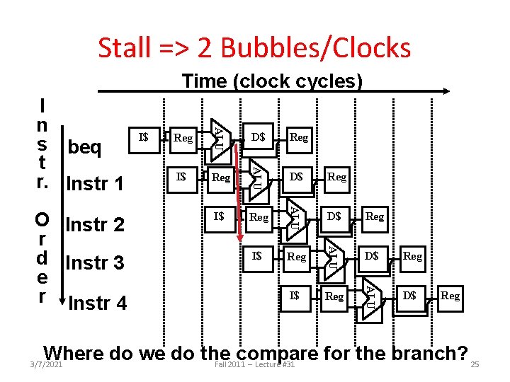
3. Control Hazards • Branch determines flow of control – Fetching next instruction depends on branch outcome – Pipeline can’t always fetch correct instruction • Still working on ID stage of branch • BEQ, BNE in MIPS pipeline • Simple solution Option 1: Stall on every branch until have new PC value – Would add 2 bubbles/clock cycles for every Branch! (~ 20% of instructions executed) 3/7/2021 Fall 2011 -- Lecture #31 24
Stall => 2 Bubbles/Clocks Time (clock cycles) Reg D$ Reg I$ Reg ALU I$ D$ ALU Reg ALU O Instr 2 r d Instr 3 e r Instr 4 I$ ALU I n s beq t r. Instr 1 D$ Reg Where do we do the compare for the branch? 25 Fall 2011 -- Lecture #31 3/7/2021
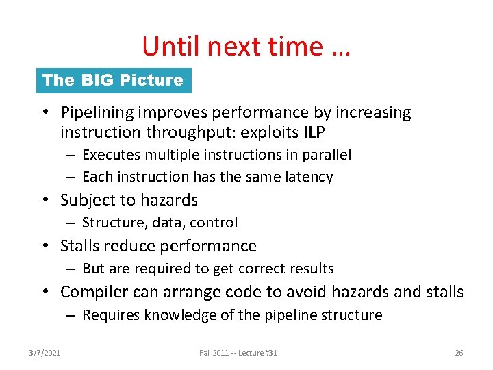
Until next time … The BIG Picture • Pipelining improves performance by increasing instruction throughput: exploits ILP – Executes multiple instructions in parallel – Each instruction has the same latency • Subject to hazards – Structure, data, control • Stalls reduce performance – But are required to get correct results • Compiler can arrange code to avoid hazards and stalls – Requires knowledge of the pipeline structure 3/7/2021 Fall 2011 -- Lecture #31 26