6 Steps to Load Planning 1 IDENTIFY EQUIPMENT


 CHARACTERISTICS Passenger Considerations Maximum Takeoff Weight: Basic Operating Weight: Planning ACL: Optimum")


 Maximum Takeoff Weight: Basic Operating Weight: Planning ACL: Optimum Zero Fuel")
 Maximum Takeoff Weight: Basic Operating Weight: Planning ACL: Optimum Zero Fuel")
- Slides: 11
6 Steps to Load Planning 1. IDENTIFY EQUIPMENT / PERSONNEL FOR AIRLIFT § 2. REFERENCE ATTLA CERTS FOR APPLICABLE EQUIPMENT § 3. AIRCRAFT LOADING INSTRUCTIONS PLACE EQUIPMENT ON AIRCRAFT(S) § § 4. +/- 5 PERCENT VARIANCE FROM TPFDD AROUND AIRCRAFT’S OPTIMAL CG PYRAMID OR 50 / 50 ADHERE TO AIRCRAFT LIMITATIONS(VISIBLE LAYERS “CONSTRAINT REGIONS”) § ROLLING STOCK RESTRICTIONS § § § PALLETS RESTRICTIONS § § RESTRICTIONS NEXT TO CARGO (I. EC-17. AND C-130) OPTIMIZE AIRCRAFT CG § 6. ALWAYS LOADED LAST PASSENGERS RESTRICTIONS § 5. WEIGHT HEIGHT CUTOUTS BAGGAGE RESTRICTIONS § § AXLES, HEIGHT, WIDTH EASE OF OFF-LOAD CLOSE TO OPTIMAL AS POSSIBLE (WITHIN +/- 1 PERCENT FOR CLASS) COMPLETE HAZ DIPS WORKSHEET FOR EACHCHALK
C-5 CHARACTERISTICS Height Restrictions Items over 114 inches must be inset. Use “Height Constraint” in ICODES to maximize aircraft space. Maximum Takeoff Weight: 840, 000 lbs. (C-5 A/B) 837, 000 lbs. (C-5 M) Basic Operating Weight: 379, 000 lbs. (C-5 A/B) 384, 000 lbs. (C-5 M) Planning ACL: 130, 000 lbs. (C-5 A/B) 150, 000 lbs. (C-5 M) Optimum Zero Fuel CG: 38% 36% (when Pax/Bags not accounted for) Passenger Considerations Troop compartment is located above the aft end of the cargo compartment. A maximum of 73 rear facing seats are available for use. 156” 162” 114” 228” *Cross section of C-5 Cargo Compartment PP 1 &2 Max Wt 7, 500 lbs Max Ht 96” Note: 14” Aisleway one 88” side Maximum Weight 36, 000 lbs in any 40” Length Maximum Weight 20, 000 lbs in any 40” Length 5 1 7 Maximum Wt: 25, 000 lbs Excludes Tracked Vehicles Pallet Position (PP) 2 -34 Max Weight (Wt) 10, 355 lbs Max Height (Ht) 96” Maximum Weight 3, 600 lbs in any 20” Length 3 9 5 PP 35 &36 Max Wt 7, 500 lbs Max Ht 70” Note: 14” Aisleway one 88” side 7 2 4 1 4 5 8 **Items with heights of 114’ to 162” WILL have special loading procedures. Reference ATTLA Certification Letter when load planning. 1 5 1 8 Maximum Weight 20, 000 lbs in any 40” Length Maximum Weight 36, 000 lbs in any 40” Length 1 8 8 4 1 9 7 1 Maximum Weight 3, 600 lbs in any 20” Length 2 1 3 1
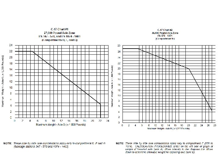
C-17 CHARACTERISTICS Tracked Vehicles Beside Single Axle Restrictions Maximum Takeoff Weight: Basic Operating Weight: Planning ACL: Optimum Zero Fuel CG: 585, 000 lbs. 284, 945 lbs. 90, 000 lbs. 40% = ZFW less than 400 K 39% = ZFW between 400 K - 425 K 38% = ZFW between 425 K - 447 K Passenger Considerations 53 Sidewall Seats 48 Centerline Seats NOTE: Sidewall seats adjacent to cargo extending past +/- 85 inches of aircraft centerline will NOT be used Compartments D, F and G: Tracked Vehicle Wt 35, 000 lbs or less 35, 001 - 65, 000 lbs Max Single Axle Wt 16, 000 lbs 11, 000 lbs Compartment E: Tracked Vehicle Wt 35, 000 lbs or less 35, 001 - 65, 000 lbs Max Single Axle Wt 24, 000 lbs 22, 000 lbs Logistic Rail System (LRS) Pallet Positions 1 R/L-9 R/L Loaded on 88” width basis Max Weight: 10, 355 lbs Max Height: 96” Aerial Delivery System (ADS) Pallet Positions 1 -11 Loaded on 108” width basis Max Weight: 10, 355 lbs Max Height: 96” Compartment F 3 4 7 Compartment D Floor Limits Compartment E Floor Limits Maximum Weight: 72, 000 lbs Maximum Weight: 170, 900 lbs Maximum Axle: 27, 000 lbs (+/- 8 inches of centerline) 22, 000 lbs (Side-by-Side) Maximum Axle: 36, 000 lbs (+/- 8 inches of centerline) 27, 000 lbs (Side-by-Side) 5 7 8 **Items with heights of 148’ to 162” WILL have special loading procedures. Reference ATTLA Certification Letter when load planning. Maximum Wt: 35, 000 lbs Compartment G Floor Limits Maximum Weight: 40, 000 lbs Maximum Axle: 27, 000 lbs (+/- 8” center) 22, 000 lbs (Sideby-Side) 1 0 7 4 1 1 6 5 Maximum Axle: 27, 000 lbs (+/- 8 inches of centerline) 22, 000 lbs (Side-by-Side) 1 4 0 3
C-130 E/H CHARACTERISTICS Passenger Considerations Maximum Takeoff Weight: Basic Operating Weight: Planning ACL: Optimum Zero Fuel CG: 155, 000 lbs. 84, 000 lbs. 25, 000 lbs. 20 -22% Max Over Land - 90 Max Over Water - 74 (Life Raft Capacity) 28 Sidewall Seats 14 Wheel Well Seats 48 Centerline Seats NOTE: Sidewall seats 1 L and 15 R are not visible in ICODES (reserved for aircrew) Pallet Position #1 Max Wt: 10, 355 lbs Max Ht 96” Note: 12” inset on one or both 88” sides about 76” height Pallet Position #2 Max Wt: 10, 355 lbs Max Ht 96” Pallet Position #3 Max Wt: 10, 355 lbs Max Ht 96” Note: 6” inset one 88” side for safety aisle Pallet Position #4 Max Wt: 10, 355 lbs Max Ht 96” Note: 6” inset one 88” side for safety aisle Outside Wheel Wells: Up to 76” = Both Sides 77” to 96” = One Side Only Greater than 97” = No Pax Most seats deploy as a set of two(2). Seat sets are bolded when passengers occupy one of the seats. Inside Wheel Wells: Up to 52” = Both Sides 53” to 72” = One Side Only Greater than 73” = No Pax NOTE: Ensure NO cargo overlaps deployed seats. Pallet Position #6 Max Wt: 4, 664 lbs Max Ht 76” Note: 20” inset on one side for safety aisle Pallet Position #5 Max Wt: 8, 500 lbs Max Ht 96” Outside the Treads NO Axles Treadway 35” Wide Starts 15” right of centerline Between the Treads Treadway 35 “ Wide tarts 15” left of centerline Treadways: 6, 000 lbs Axle 2 5 7 Treadways: 13, 000 lbs Axle 3 3 7 Treadways: 6, 000 lbs Axle 6 8 2 Between the Treads: 5, 000 lbs Axle 2, 000 lbs Tongue **Items with heights of 102’ to 108” WILL have special loading procedures. Reference ATTLA Certification Letter when load planning. 7 3 7 Outside the Treads NO Axles Treadways: 2, 500 lbs. Axles** 2, 501 – 3, 500 lbs. Axle * / ** *Nothing else loaded on Ramp **Limited to 4, 664 lbs. total Between the Treads: 1, 200 lbs. Axle 450 lbs. Tongue 8 6 9
C-130 J(S) CHARACTERISTICS Passenger Considerations Maximum Takeoff Weight: Basic Operating Weight: Planning ACL: Optimum Zero Fuel CG: 164, 000 lbs. 84, 000 lbs. 25, 000 lbs. 20 -22% Max Over Land - 90 Max Over Water - 74 (Life Raft Capacity) 28 Sidewall Seats 14 Wheel Well Seats 48 Centerline Seats NOTE: Sidewall seats 1 L and 15 R are not visible in ICODES (reserved for aircrew) Pallet Position #1 Max Wt: 10, 355 lbs Max Ht 96” Pallet Position #2 Max Wt: 10, 355 lbs Max Ht 96” Note: 12” inset on one or both 88” sides about 76” height Note: 12” inset maybe needed on one or both 88” sides about 76” height Pallet Position #3 Max Wt: 10, 355 lbs Max Ht 96” Note: 6” inset one 88” side for safety aisle Pallet Position #4 Max Wt: 10, 355 lbs Max Ht 96” Note: 6” inset one 88” side for safety aisle Outside Wheel Wells: Up to 76” = Both Sides 77” to 96” = One Side Only Greater than 97” = No Pax Most seats deploy as a set of two(2). Seat sets are bolded when passengers occupy one of the seats. Inside Wheel Wells: Up to 52” = Both Sides 53” to 72” = One Side Only Greater than 73” = No Pax NOTE: Ensure NO cargo overlaps deployed seats. Pallet Position #6 Max Wt: 5, 000 lbs Max Ht 77” Note: 20” inset on right side for safety aisle Pallet Position #5 Max Wt: 8, 500 lbs Max Ht 96” Outside the Treads NO Axles Treadway 35” Wide Starts 15” right of centerline Between the Treads Treadway 35 “ Wide tarts 15” left of centerline Treadways: 6, 000 lbs Axle 2 5 7 Treadways: 13, 000 lbs Axle 3 3 7 Treadways: 6, 000 lbs Axle 6 8 2 Between the Treads: 5, 000 lbs Axle 2, 000 lbs Tongue **Items with heights of 102’ to 108” WILL have special loading procedures. Reference ATTLA Certification Letter when load planning. 7 3 7 Outside the Treads NO Axles Treadways: 2, 500 lbs. Axles** 2, 501 – 3, 500 lbs. Axle * / ** *Nothing else loaded on Ramp **Limited to 5, 000 lbs. total Between the Treads: 1, 200 lbs. Axle 450 lbs. Tongue 8 6 9
C-130 J-30 CHARACTERISTICS Maximum Takeoff Weight: Basic Operating Weight: Planning ACL: Optimum Zero Fuel CG: 164, 000 lbs. 89, 000 lbs. 40, 000 lbs. 20 -22% Passenger Considerations Max Over Land - 126 Max Over Water - 126 46 Sidewall Seats 14 Wheel Well Seats 66 Centerline Seats NOTE: Sidewall seats 1 L and 2 L are not visible in ICODES (reserved for aircrew) PP #1 Max Wt 10, 355 lbs Max Ht 96” Note: 12” inset on one/both 88” sides about 76” height PP #2 Max Wt 10, 355 lbs Max Ht 96” Note: 12” inset maybe needed on one/both 88” sides about 76” ht PP #3 Max Wt: 10, 355 lbs Max Ht 96” PP #4 Max Wt 10, 355 lbs Max Ht 96” Note: 6” inset one 88” side for safety aisle PP #5 Max Wt 10, 355 lbs Max Ht 96” Note: 6” inset one 88” side for safety aisle Most seats deploy as a set of two(2). Seat sets are bolded when passengers occupy one of the seats. Outside Wheel Wells: Up to 76” = Both Sides 77” to 96” = One Side Only Greater than 97” = No Pax Inside Wheel Wells: Up to 52” = Both Sides 53” to 72” = One Side Only Greater than 73” = No Pax PP #6 Max Wt: 10, 355 lbs Max Ht 96” NOTE: Ensure NO cargo overlaps deployed seats. PP #8 Max Wt 5, 000 lbs Max Ht 77” Note: 20” inset on right side for safety aisle PP #7 Max Wt 8, 500 lbs Max Ht 96” Outside the Treads NO Axles Treadway 35” Wide Starts 15” right of centerline Between the Treads Treadway 35” Wide Starts 15” left of centerline Treadways: 6, 000 lbs Axle 3 4 5 Treadways: 13, 000 lbs Axle 5 3 7 8 8 2 Between the Treads: 5, 000 lbs Axle 2, 000 lbs Tongue **Items with heights of 102’ to 108” have special loading procedures. Reference ATTLA Certification Letter when load planning. Treadways: 6, 000 lbs Axle 2, 500 lbs. Axles** 2, 501 – 3, 500 lbs Axle * / ** *Nothing else load’d on Ramp **Limited to 5, 000 lbs. total 1 0 1 7 Between the Treads: 1 1, 200 lbs. Axle 450 lbs. Tongue 1 3 3 Outside the Treads NO Axles
C-130 J-30 COMPARTMENT LIMITATIONS TO 1 C-130 J-9 Figure 2 -4 NOTE: THESE ARE FLIGHT LIMITS FOR THE C-130 J-30 WITH A GROSS WEIGHT OF 155, 000 LBS. AT 2. 25/2. 5 G WITH NO ARMOR (ICODES STANDARD). REFER TO FIGURE 2 -4 FOR AIRCRAFT WITH DIFFERENT GROSS WEIGHTS AND EQUIPPED WITH ARMOR. C 5, 500 lbs. C-D 9, 500 lbs. C-E 13, 700 lbs. C-F 19, 300 lbs. C-G 23, 400 lbs. C-H 29, 800 lbs. 47, 800 lbs. 22, 325 lbs. 15, 500 lbs. 5, 300 lbs. 5, 000 lbs. 2, 500 lbs. THESE LIMITATIONS MUST BE USED ALONG WITH THE GROSS WEIGHT, CENTER OF GRAVITY, FLOOR LOADING AND MAXIMUM CARGO WEIGHT LIMITS OF THE AIRCRAFT. THE LESSER OF ALL THESE INDIVIDUAL LIMITATIONS DEFINE THE FINAL LIMITATION. 3 4 5 3 8 3 4 7 2 5 6 2 6 5 2 7 4 2 8 3 2 9 2 2 1 0 1 1 1 0 4 2 H-M I-M J-M K-M L-M M 1 1 2 4 1 1 4 1
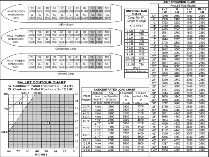
KC-10 CHARACTERISTICS (B-1) Maximum Takeoff Weight: Basic Operating Weight: Planning ACL: Optimum Zero Fuel CG: 590, 000 lbs. 251, 631 lbs. 65, 200 lbs. 24% Passenger Considerations 16 Seats NOTE: 3 -8 seats Reserved for Aircrew depending on Mission needs *PP 10 R/L and 11 R/L Special Notes: 10 R/L is limited to 7, 000 lbs when pallet contains concentrated loads TO 1 C-10(K)A-9 Reference Charts All Cargo: “Pallet Contour Chart and Aisle Configuration” (Figure 4 -2) Uniform Loads: Pounds per Linear Foot (PLF) “Load Data” (Figure 4 -7) Concentrated Loads: “Concentrated Load Limitations “ (Figure 4 -19) Vehicles: “Vehicle Axle Weight Limitations “ (Figure 4 -20) Items Exceeding Coupled Pallet (T-2) Dimensions: “Package Size Chart” (Figure 4 -3) 11 R/L is limited 7, 500 lbs when pallet contains concentrated loads 10 R/L and 11 R/L is limited to 8, 000 lbs when loaded with axles. D Contour C Contour PP 2 R / 2 L PP 3 R / 3 L PP 5 R / 5 L PP 4 R / 4 L PP 6 R / 6 L Max Wt: 6, 500 Max Wt: 6, 500 lbs lbs lbs Max Ht 96” Max Ht 96” Max Axle: 4, 500 lbs (PP 2 R/L – 5 R/L) 6 3 0 1 0 6 6 Max Axle: 4, 800 lbs (PP 6 R/L) PP 7 R / 7 L Max Wt: 10, 000 lbs Max Ht 96” 1 1 7 5 PP 8 R / 8 L Max Wt: 10, 000 lbs Max Ht 96” Max Axle: 3, 200 lbs (PP 7 R/L – 9 R/L) NOTE: If distance between axles is less than 48” Refer to the “Axle Reduction Chart” **Items with heights over 96” WILL have special loading procedures. Reference ATTLA Certification Letter when load planning. PP 9 R / 9 L Max Wt: 10, 000 lbs Max Ht 96” 1 5 0 2 *PP 10 R / 10 L *PP 11 R / 11 L Max Wt: 10, 000 lbs Max Ht 96” *7, 000 lbs Concentrated Max Wt: 10, 000 lbs Max Ht 96” *7, 500 lbs Concentrated PP 12 R / 12 L Max Wt: 6, 500 lbs Max Ht 96” Max Axle: 4, 000 lbs (PP 10 R/L – 12 R/L) 1 8 2 9
KC-10 CHARACTERISTICS (D-1) Maximum Takeoff Weight: Basic Operating Weight: Planning ACL: Optimum Zero Fuel CG: 590, 000 lbs. 256, 615 lbs. 65, 200 lbs. 24% Passenger Considerations 75 Seats NOTE: 3 -8 seats Reserved for Aircrew depending on Mission needs *PP 10 R/L and 11 R/L Special Notes: 10 R/L is limited to 7, 000 lbs when pallet contains concentrated loads 11 R/L is limited 7, 500 lbs when pallet contains concentrated loads TO 1 C-10(K)A-9 Reference Charts All Cargo: “Pallet Contour Chart and Aisle Configuration” (Figure 4 -2) Uniform Loads: Pounds per Linear Foot (PLF) “Load Data” (Figure 4 -7) Concentrated Loads: “Concentrated Load Limitations “ (Figure 4 -19) Vehicles: “Vehicle Axle Weight Limitations “ (Figure 4 -20) Items Exceeding Coupled Pallet (T-2) Dimensions: “Package Size Chart” (Figure 4 -3) 10 R/L and 11 R/L is limited to 8, 000 lbs when loaded with axles. D Contour C Contour PP 5 R / 5 L PP 6 R / 6 L Max Wt: 6, 500 lbs Max Ht 96” 9 7 5 Max Axle: 4, 500 lbs (PP 5 R/L) 1 0 6 6 Max Axle: 4, 800 lbs (PP 6 R/L) PP 7 R / 7 L Max Wt: 10, 000 lbs Max Ht 96” PP 8 R / 8 L Max Wt: 10, 000 lbs Max Ht 96” Max Axle: 3, 200 lbs (PP 7 R/L – 9 R/L) 1 1 7 5 PP 9 R / 9 L Max Wt: 10, 000 lbs Max Ht 96” PP 10 R / 10 L PP 11 R / 11 L Max Wt: 10, 000 lbs Max Ht 96” *7, 000 lbs Concentrated Max Ht 96” *7, 500 lbs Concentrated 1 5 0 2 NOTE: If distance between axles is less than 48” Refer to the “Axle Reduction Chart” **Items with heights over 96” WILL have special loading procedures. Reference ATTLA Certification Letter when load planning. PP 12 R / 12 L Max Wt: 6, 500 lbs Max Ht 96” Max Axle: 4, 000 lbs (PP 10 R/L – 12 R/L) 1 8 2 9