6 Really Basic Optics Sample Prep Polychromatic light

6. Really Basic Optics Sample Prep Polychromatic light Select light source select Instrument Selected light Instrument Out put Signal (Data) Turn off/diminish intensity Sample interaction Turn on different wavelength detect

Really Basic Optics Key definitions Phase angle Atomic lines vs molecular bands Atomic Line widths (effective; natural) Doppler broadening Molecular bands Continuum sources Blackbody radiators Coherent vs incoherent radiation

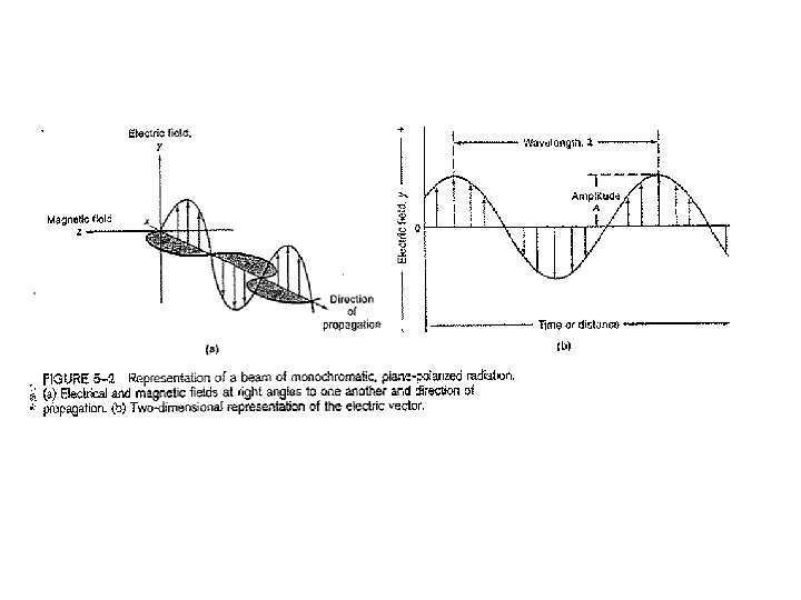
6. Really Basic Optics A Sin=opp/hyp y /2 90 o phase angle /2 radian phase angle 3 /2 2

Emission of Photons Electromagnetic radiation is emitted when electrons relax from excited states. A photon of the energy equivalent to the difference in electronic states Is emitted Ehi e Elo Frequency 1/s

Really Basic Optics Key definitions Phase angle Atomic lines vs molecular bands Atomic Line widths (effective; natural) Doppler broadening Molecular bands Continuum sources Blackbody radiators Coherent vs incoherent radiation
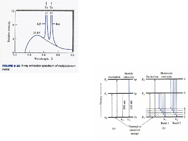

Theoretical width of an atomic spectral line

Natural Line Widths Line broadens due 1. Uncertainty 2. Doppler effect 3. Pressure 4. Electric and magnetic fields frequency Lifetime of an excited state is typically 1 x 10 -8 s

Example: 253. 7 nm Typical natural line widths are 10 -5 nm

Line broadens due 1. Uncertainty 2. Doppler effect 3. Pressure 4. Electric and magnetic fields

Line broadens due 1. Uncertainty 2. Doppler effect 3. Pressure 4. Electric and magnetic fields The lifetime of a spectral event is 1 x 10 -8 s When an excited state atom is hit with another high energy atom energy is transferred which changes the energy of the excited state and, hence, the energy of the photon emitted. This results in linewidth broadening. The broadening is Lorentzian in shape. We use pressure broadening On purpose to get a large Line width in AA for some Forms of background correction FWHM = full width half maximum o is the peak “center” in frequency units

Line spectra – occur when radiating species are atomic particles which Experience no near neighbor interactions Line broadens due 1. Uncertainty 2. Doppler effect 3. Pressure 4. Electric and magnetic fields Line events Can lie on top Of band events Overlapping line spectra lead to band emission

Continuum emission – an extreme example of electric and magnetic effects on broadening of multiple wavelengths High temperature solids emit Black Body Radiation many over lapping line and band emissions influenced by near neighbors

Stefan-Boltzmann Law Planck’s Blackbody Law = Energy density of radiation h= Planck’s constant C= speed of light k= Boltzmann constant T=Temperature in Kelvin = frequency Wien’s Law 1. As ↓ (until effect of exp takes over) 2. As T , exp↓,

Really Basic Optics Key definitions Phase angle Atomic lines vs molecular bands Atomic Line widths (effective; natural) Doppler broadening Molecular bands Continuum sources Blackbody radiators Coherent vs incoherent radiation

Incoherent radiation The Multitude of emitters, even if they emit The same frequency, do not emit at the Same time A B Frequency, , is the Same but wave from particle B lags behind A by the Phase angle

END: Key Definitions Begin Using Constructive and Destructive Interference patterns based on phase lag By manipulating the path length can cause an originally coherent beam (all in phase, same frequency) to come out of phase can accomplish Many of the tasks we need to control light for our instruments Constructive/Destructive interference 1. Laser 2. FT instrument 3. Can be used to obtain information about distances 4. Interference filter. 5. Can be used to select wavelengths

More Intense Radiation can be obtained by Coherent Radiation Lasers Beam exiting the cavity is in phase (Coherent) and therefore enhanced In amplitude

Argument on the size of signals that follows is from Atkins, Phys. Chem. p. 459, 6 th Ed Stimulated Emission Light Amplification by Stimulated Emission of Radiation * o Photons can stimulate Emission just as much As they can stimulate Absorption (idea behind LASERs Stimulated Emission) The rate of stimulated event is described by : Where w =rate of stimulated emission or absorption Is the energy density of radiation already present at the frequency of The more perturbing photons the greater the transition Stimulated emission B= empirical constant known as the Einstein coefficient for stimulated absorption or emission N* and No are the populations of upper state and lower states

can be described by the Planck equation for black body radiation at some T frequency In order to measure absorption it is required that the Rate of stimulated absorption is greater than the Rate of stimulated emission If the populations of * and o are the same the net absorption is zero as a photon is Absorbed and one is emitted

Need to get a larger population in the excited state Compared to the ground state (population inversion) Degeneracies of the different energy levels Special types of materials have larger excited state degeneracies Which allow for the formation of the excited state population inversion E pump Serves to “trap” electrons in the excited State, which allows for a population inversion

Constructive/Destructive interference 1. Laser 2. FT instrument 3. Can be used to select wavelengths 4. Can be used to obtain information about distances 5. Holographic Interference filter. Radiation not along the Path is lost mirror Multiple directions, Multiple phase lags Incoherent radiation mirror Stimulated emission 1. Single phase 2. Along same path =Constructive Interference Coherent radiation

FTIR Instrument Constructive/Destructive interference 1. Laser 2. FT instrument 3. Can be used to select wavelengths 4. Can be used to obtain information about distances 5. Holographic Interference filter.

Time Domain: 2 frequencies 1 “beat” cycle

B A Moving mirror Fixed mirror C Beam splitter IR source detector Constructive interference occurs when

-2 -1 0 +1

INTERFEROGRAMS Remember that: Frequency of light

An interferometer detects a periodic wave with a frequency of 1000 Hz when moving at a velocity of 1 mm/s. What is the frequency of light impinging on the detector?

No need to SELECT Wavelength by using Mirror, fiber optics, Gratings, etc.

FOURIER TRANSFORMS Advantages 1. Jaquinot or through-put little photon loss; little loss of source intensity 2. Large number of wavelengths allows for ensemble averaging (waveform averaging) 3. This leads to Fellget or multiplex advantage multiple spectra in little time implies?

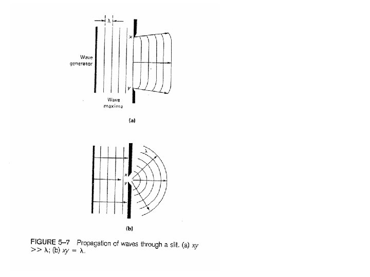
DIFFRACTION Huygen’s principle = individual propagating waves combine to form a new wave front Constructive/Destructive interference 1. Laser 2. FT instrument 3. Can be used to select wavelengths 4. Can be used to obtain information about distances 5. Holographic Interference filter. Can get coherent radiation if the slit is narrow enough. Coherent = all in one phase

June 19, 2008, Iowa Flood Katrina Levee break

Fraunhaufer diffraction at a single slit

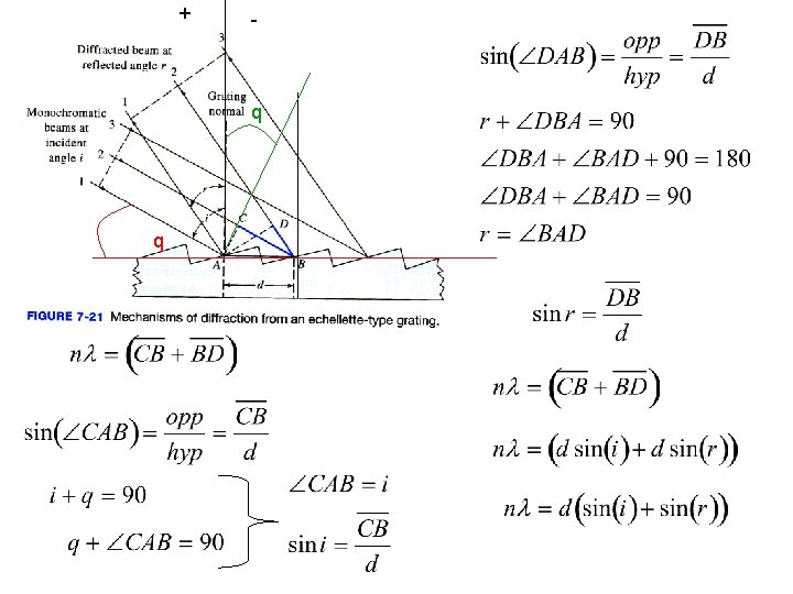
D d B W O C F’ F From which we conclude L E

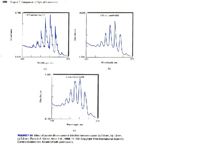
D The complete equation for a slit is d B W L b=W/2 E Width of the line depends upon The slit width!! Therefore resolution depends On slit width Also “see” This spectra “leak” of Our hard won intensity
 occurs whenever sinβ =0 Which occurs when The smaller the")
The base (I =0) occurs whenever sinβ =0 Which occurs when The smaller the Slit width the Smaller The line width, Which leads To greater Spectral Resolution Remember R is Inversely proportional To the width of The Gaussian base

A 1 2 3 B Image Slit SLIT IMAGE 1234 5 Detector output: Position number When edge AB at Position 1 Position 2 Position 3 Position 4 Position 5 Detector Sees 0% power 50% power 100% power 50% power 0 % power Triangle results when Effective bandpass = image To resolve two images that are ∆ apart requires Implies want a narrower slit

Essentially, Narrow slit widths Are generally better

GRATINGS Gratings UV/Vis IR Groves/mm 300/2000 10/20 Points: 1. Master grating formed by diamond tip under ground 1. Or more recently formed from holographic processes 2. Copy gratings formed from resins
 Get")
EXAMPLE Calculate for a grating which has i=45 2000 groves per mm 1) Get d 2) Use grating equation to solve for

Czerny-Turner construction You get light of 674. 9 nm ½; 1/3; 1/4; 1/5; etc. 440. 3 220. 1 146. 8 88 73 All come through Multiple wavelengths Are observed At a single angle Of reflection!!

Physical Dimensions: 89. 1 mm x 63. 3 mm x 34. 4 mm Weight: 190 grams Detector: Sony ILX 511 linear silicon CCD array Detector range: 200 -1100 nm Pixels: 2048 pixels Pixel size: 14 μm x 200 μm Pixel well depth: ~62, 500 electrons Sensitivity: 75 photons/count at 400 nm; 41 photons/count at 600 nm Czerny-Turner Focal length: 42 mm input; 68 mm output construction Entrance aperture: 5, 10, 25, 50, 100 or 200 µm wide slits or fiber (no slit) Design: f/4, Symmetrical crossed Czerny-Turner Grating options: 14 different gratings, UV through Shortwave NIR Detector collection lens option: Yes, L 2 OFLV filter options: OFLV-200 -850; OFLV-350 -1000 Other bench filter options: Longpass OF-1 filters Collimating and focusing mirrors: Standard or SAG+ UV enhanced window: Yes, UV 2 Fiber optic connector: SMA 905 to 0. 22 numerical aperture single-strand optical fiber Spectroscopic Wavelength range: Grating dependent Optical resolution: ~0. 3 -10. 0 nm FWHM Signal-to-noise ratio: 250: 1 (at full signal) A/D resolution: 12 bit Dark noise: 3. 2 RMS counts Dynamic range: 2 x 10^8 (system); 1300: 1 for a single acquisition Integration time: 3 ms to 65 seconds Stray light: <0. 05% at 600 nm; <0. 10% at 435 nm Corrected linearity: >99. 8% Electronics Power consumption: 90 m. A @ 5 VDC Data transfer speed: Full scans to memory every 13 ms with USB 2. 0 or 1. 1 port, 300 ms with serial port

Ocean Optics For fluorescence lab 440. 3 220. 1 146. 8 88 73 All come through Monochromator we looked inside 440. 3 Only Hit grating first Time to get 440. 3 220. 1 146. 8 88 73 All come through Hit grating second time 220. 1 nm

Another way to look at it is to say We Lose some of the light Not all of it ends up at the intended angle of reflection Light of 100 Nm shows up At -30. 4 AND -17. 88 And -6. 1 And 5. 3 Etc.

GRATING DISPERSION D-1 = Reciprocal linear dispersion Where n= order F = focal length d= distance/groove POINT = linear dispersion
 the wavelength(s) transmitted at 45 o reflected AND incident light for")
What is (are) the wavelength(s) transmitted at 45 o reflected AND incident light for a grating of 4000 groves/mm?

RESOLUTION The larger R the greater the spread between the two wavelengths, normalized by The wavelength region Where n = order and N = total grooves exposed to light

What is the resolution of a grating in the first order of 4000 groves/mm if 1 cm of the grating is illuminated? Are 489 and 489. 2 nm resolved?

Constructive/Destructive interference 1. Laser 2. FT instrument 3. Can be used to select wavelengths 4. Can be used to obtain information about distances 5. Holographic Interference filter. Change in path length results In phase lag The photo plate contains all the information Necessary to give the depth perception when decoded

Interference Filter Holographic Notch Filter Can create a filter using The holographic principle To create a series of Groves on the surface Of the filter. The grooves Are very nearly perfect In spacing Constructive/Destructive interference 1. Laser 2. FT instrument 3. Can be used to obtain information about distances 4. Interference filter. 5. Can be used to select wavelengths

End Section on Using Constructive and Destructive Interference patterns based on phase lags Constructive/Destructive interference 1. Laser 2. FT instrument 3. Can be used to obtain information about distances 4. Interference filter. 5. Can be used to select wavelengths

Begin Section Interaction with Matter In the examples above have assumed that there is no interaction with Matter – all light that impinges on an object is re-radiated with it’s Original intensity
 Re-radiate “virtual state” Lasts ~10 -14 s")
Move electrons around (polarize) Re-radiate “virtual state” Lasts ~10 -14 s
 Re-radiate This phenomena causes: 1. scattering 2. change in the")
Move electrons around (polarize) Re-radiate This phenomena causes: 1. scattering 2. change in the velocity of light 3. absorption

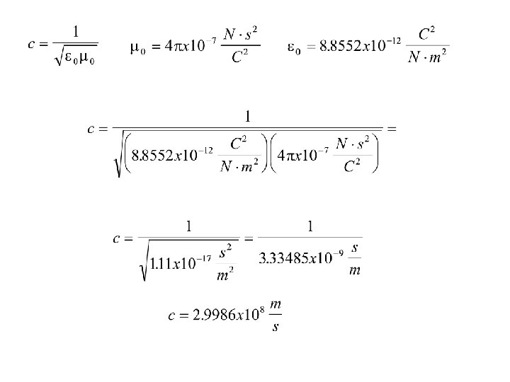
First consider propagation of light in a vacuum c is the velocity of the electromagnetic wave in free space Is the permittivity of free space which describes the Flux of the electric portion of the wave in vacuum and Has the value capacitance force It can be measured directly from capacitor measurements Is the permeablity of free space and relates the current In free space in response to a magnetic field and is defined as
 Says: refractive")
Dielectric constant Typically so This works pretty well for gases (blue line) Says: refractive index is proportional to the dielectric Maxwell’s relation constant

Our image is of electrons perturbed by an electromagnetic field which causes The change in permittivity and permeability – that is there is a “virtual” Absorption event and re-radiation causing the change It follows that the re-radiation event should be be related to the ability to Polarize the electron cloud 10 -14 s to polarize the electron cloud and re-release electromagnetic Radiation at same frequency

SCATTERING Light in particle Most important parameter is the relationship to wavelength Angle between incident and scattered light Polarizability of electrons a) Number of electrons b) Bond length c) Volume of the molecule, which depends upon the radius, r = vacuum Io = incident intensity
 light")
At sunset the shorter wavelength is Scattered more efficiently, leaving the Longer (red) light to be observed Better sunsets in polluted regions Blue is scattered Red is observed Long path allow more of the blue light (short wavelength) to be scattered

What is the relative intensity of scattered light for 480 vs 240 nm? What is the relative intensity of scattered light as one goes from Cl 2 to Br 2? (Guess)

Our image is of electrons perturbed by an electromagnetic field which causes The change in permittivity and permeability – and therefore, the speed of the Propagating electromagnetic wave. It follows that the index of refraction should be related to the ability to Polarize the electron cloud

Refractive index = relative speed of radiation Refractive index is related to the relative permittivity (dielectric constant) at that Frequency Where is the mass density of the sample, M is the molar mass of the molecules and Pm is the molar polarization Is the permittivity of free space which describes the Flux of the electric portion of the wave in vacuum and Has the value Where is the electric dipole moment operator is the mean polarizabiltiy Point – refractive index Is related to polarizability Clausius-Mossotti equation

Where e is the charge on an electron, R is the radius of the molecule and ∆E is the mean energy to excite an electron between the HOMO-LUMO The change in the velocity of the electromagnetic radiation is a function of 1. mass density (total number of possible interactions) 2. the charge on the electron 3. The radius (essentially how far away the electron is from the nucleus) 4. The Molar Mass (essentially how many electrons there are) 5. The difference in energy between HOMO and LUMO

An alternative expression for a single atom is Transition probability that Interaction will occur Molecules per Unit volume Each with J oscillators A damping force term that account for Absorbance (related to delta E in prior Expression) Natural Frequency of The oscillating electrons In the single atom j Frequency of incoming electromagnetic wave If you include the interactions between atoms and ignore absorbance you get

when The refractive index is constant The refractive index depends on omega And the difference Gets smaller so the Refractive index rises

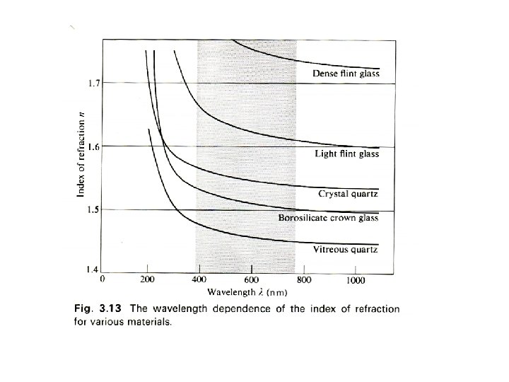
REFRACTIVE INDEX VS Anomalous dispersion near absorption bands which occur at natural harmonic frequency of material Normal dispersion is required for lensing materials

What is the wavelength of a beam of light that is 480 nm in a vacuum if it travels in a solid with a refractive index of 2?

Filters can be constructed By judicious combination of the Principle of constructive and Destructive interference and Material of an appropriate refractive index t Wavelength In media t t
 the wavelength(s) selected from an interference filter which has a base")
What is (are) the wavelength(s) selected from an interference filter which has a base width of 1. 694 m and a refractive index of 1. 34?

Holographic filters are better

INTERFERENCE WEDGES AVAILABLE WEDGES Vis Near IR IR 400 -700 nm 1000 -2000 nm 2. 5 -14. 5 m

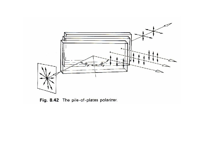
Using constructive/destructive interference to select for polarized light The electromagnetic wave can be described in two components, xy, and Xy - or as two polarizations of light.

Refraction, Reflection, and Transmittance Defined Relationship to polarization The amplitude of the spherically oscillating electromagnetic Wave can be described mathematically by two components The perpendicular and parallel to a plane that described the advance of The waveform. These two components reflect the polarization of the wave

When this incident, i, wave plane strikes a denser surface with polarizable electrons at an angle, i, described by a perpendicular to The plane It can be reflected Air, n=1 Or transmitted R The two polarization components are reflected and transmitted with Different amplitudes depending Upon the angle of reflection, r, And the angle of transmittence, t Glass n=1. 5 T Let’s start by examing The Angle of transmittence

Tim Snell’s Law e= 4 Tim e= 3 Tim e= 2 Tim e= Tim 1 e= 0 4 e= Tim e=3 2 Tim e= 1 Tim e=0 Tim Less dense 1 Lower refractive index Faster speed of light More dense 1 Higher refractive index Slower speed of light

What is the angle of refraction, 2, for a beam of light that impinges on a surface at 45 o, from air, refractive index of 1, to a solid with a refractive index of 2?
 400 nm 1. 532 450 nm 1. 528 550 nm")
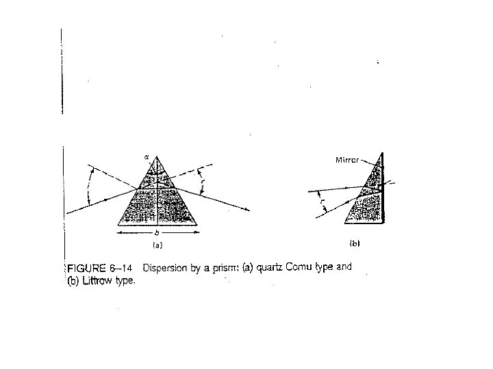
PRISM Crown Glass (nm) 400 nm 1. 532 450 nm 1. 528 550 nm 1. 519 590 nm 1. 517 620 nm 1. 514 650 nm 1. 513 Uneven spacing = nonlinear POINT, non-linear dispersive device Reciprocal dispersion will vary with wavelength, since refractive index varies with wavelength
 reflected as compared to transmitted (refracted)")
The intensity of light (including it’s component polarization) reflected as compared to transmitted (refracted) can be described by the Fresnel Equations R Angle of transmittence Is controlled by The density of Polarizable electrons In the media as Described by Snell’s Law T

The amount of light reflected depends upon the Refractive indices and the angle of incidence. We can get Rid of the angle of transmittence using Snell’s Law Since the total amount of light needs to remain constant we also know that Therefore, given the two refractive Indices and the angle of incidence can Calculate everything

Consider and air/glass interface i Here the transmitted parallel light is Zero! – this is how we can select For polarized light! This is referred to as the polarization angle

Total Internal Reflection Here consider Light propagating In the DENSER Medium and Hitting a Boundary with The lighter medium Glass n=1. 5 R Air, n=1 T

Same calculation but made the indicident medium denser so that wave is Propagating inside glass and is reflected at the air interface Discontinuity at 42 o signals Something unusual is happening

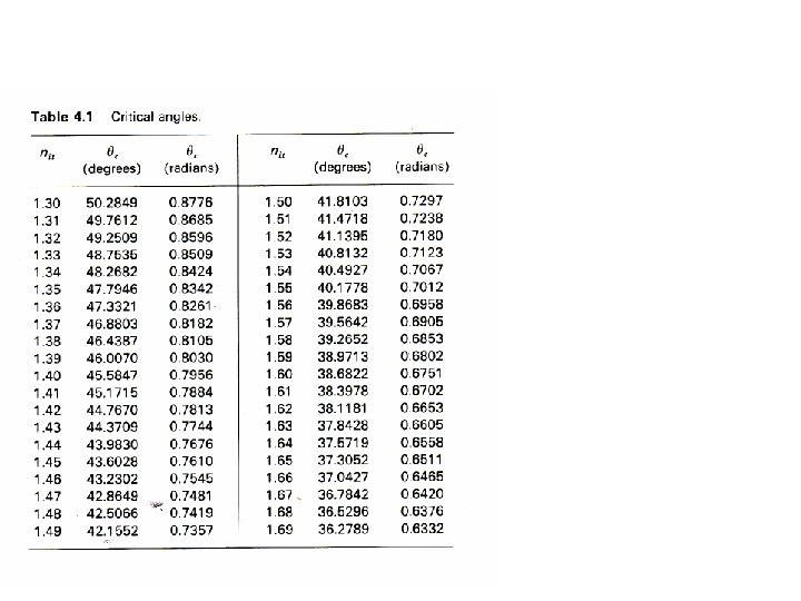
All of the light is reflected internally Set R to 1 & to 90 The equation can be solved for the critical angle of incidence For glass/air

The angle at which the discontinuity occurs: 1. 0% Transmittance=100% Reflectance 2. Total Internal Reflectance 3. Angle = Critical Angle – depends on refractive index 1. 69/1 1. 3/1 1. 5/1 37 42 51

Numerical Aperture The critical angle here is defined differently because we have to LAUNCH the beam

Shining light directly through our sample i=0 Using Snell’s Law the angle of transmittance is R=? T

same The amount of light reflected depends Upon the refractive indices of the medium

For a typical Absorption Experiment, How much light will we lose from the cuvette? Or another way to put it is how much light will get transmitted?

Io It=I’o Water, refractive index 1. 33 It’ = I’’o It’’ = I’’’o It’’’ Air, refractive index 1 Air Glass, refractive index 1. 5 Final exiting light

We lose nearly 10% of the light

Key Concepts Interaction with Matter Light Scattering Refractive Index Is wavelength dependent Used to separate light by prisms Refractive index based Interference filters

Key Concepts Interaction with Matter Snell’s Law Describes how light is bent based differing refractive indices Fresnell’s Equations describe how polarized light is transmitted and/or reflected at an interface Used to create surfaces which select for polarized light

Key Concepts Interaction with Matter Fresnell’s Laws collapse to Which describes when you will get total internal reflection (fiber optics) And Which describes how much light is reflected at an interface

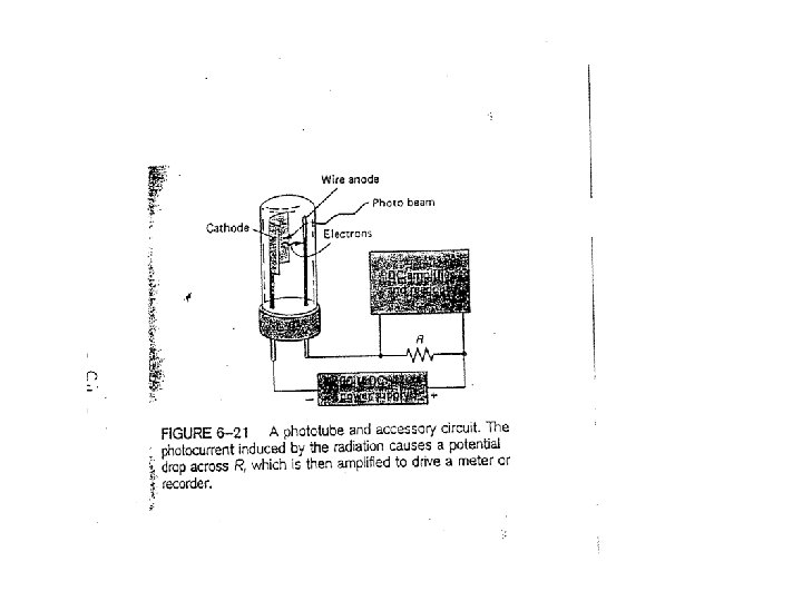
PHOTONS AS PARTICLES The photoelectric effect: The experiment: 1. Current, I, flows when Ekinetic > Erepulsive 2. E repulsive is proportional to the applied voltage, V 3. Therefore the photocurrent, I, is proportional to the applied voltage 4. Define Vo as the voltage at which the photocurrent goes to zero = measure of the maximum kinetic energy of the electrons 5. Vary the frequency of the photons, measure Vo, = Ekinetic, max Energy of Ejected electron Work function=minimum energy binding an Electron in the metal Frequency of impinging photon (related to photon energy)

To convert photons to electrons that we can measure with an electrical circuit use A metal foil with a low work function (binding energy of electrons)

DETECTORS Ideal Properties 1. High sensitivity 2. Large S/N 3. Constant parameters with wavelength Where k is some large constant kd is the dark current Classes of Detectors Name comment Photoemissive single photon events Photoconductive “ (UV, Vis, near IR) Heat average photon flux Want low dark current

Very sensitive detector Rock to Get different wavelengths 1. Capture all simultaneously = multiplex advantage 2. Generally less sensitive

Sensitivity of photoemissive Surface is variable Ga/As is a good one As it is more or less consistent Over the full spectral range
")
Diode array detectors -Great in getting -A spectra all at once! Background current (Noise) comes from? One major problem -Not very sensitive -So must be used -With methods in -Which there is a large -signal

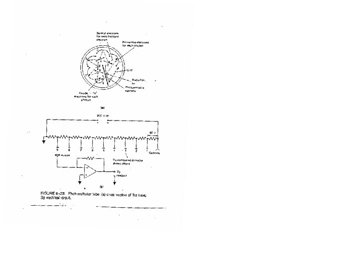
Photomultiplier tube The AA experiment Photodiodes
 1. Are miniature – therefore do not")
The fluorescence experiment Charge-Coupled Device (CCD detectors) 1. Are miniature – therefore do not need to “slide” the image across a single detector (can be used in arrays to get a Fellget advantage) 2. Are nearly as sensitive as a photomultiplier tube 1. Set device to accumulate charge for some period of time. (increase sensitivity) 2. Charge accumulated near electrode +V 3. Apply greater voltage 4. Move charge to “gate” And Count, 5. move next “bin” of charge and keep on counting 6. Difference is charge in One “bin” Requires special cooling, Why?

END 6. Really Basic Optics

Since polarizability of the electrons in the material also controls the dielectric Constant you can find a form of the C-M equation with allows you to compute The dielectric constant from the polarizability of electrons in any atom/bond N = density of dipoles = polarizability (microscopic (chemical) property) r = relative dielectric constant Frequency dependent Just as the refractive index is Typically reported Point of this slide: polarizability of electrons in a molecule is related to the Relative dielectric constant

2 nd order 1 st order Grating Angle of reflection i=45

2 nd order 1 st order Angle of reflection i=45
- Slides: 116