6 MAXWELLS EQUATIONS IN TIMEVARYING FIELDS Applied EM


 induced by time-varying magnetic flux:")


- Slides: 30
6. MAXWELL’S EQUATIONS IN TIME-VARYING FIELDS Applied EM by Ulaby, Michielssen and
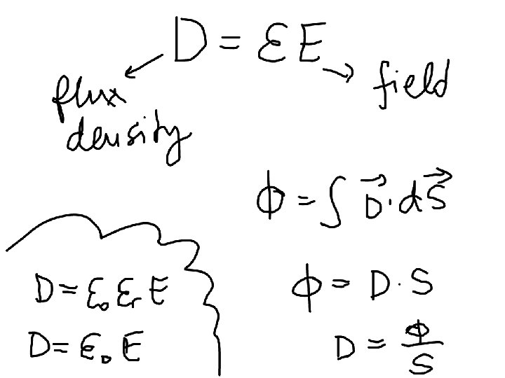
Maxwell’s Equations In this chapter, we will examine Faraday’s and Ampère’s laws
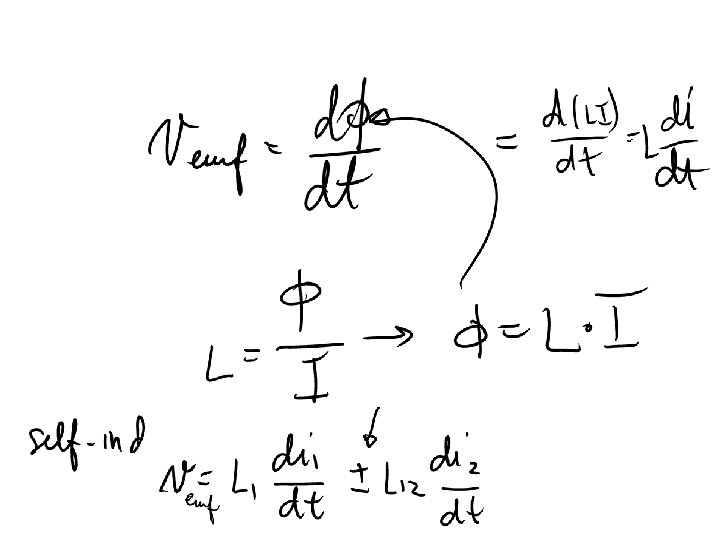
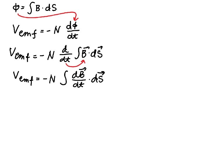
Faraday’s Law Electromotive force (voltage) induced by time-varying magnetic flux:
Faraday’s Experimental Setup Galvanometer Coupled Coils https: //en. wikipedia. org/wiki/Faraday's_law _of_induction#/media/File: Induction_experi ment. png Battery
Three types of EMF
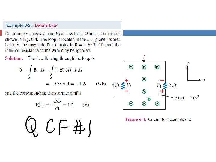
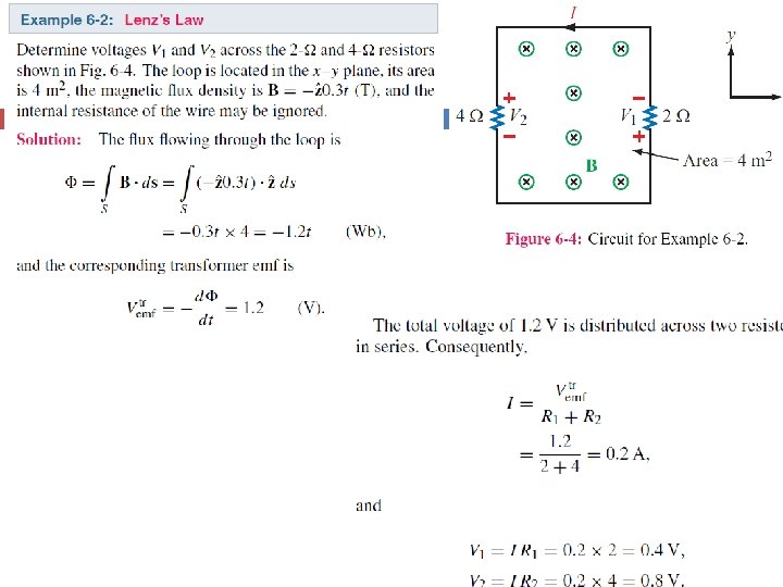
Lenz’s Law
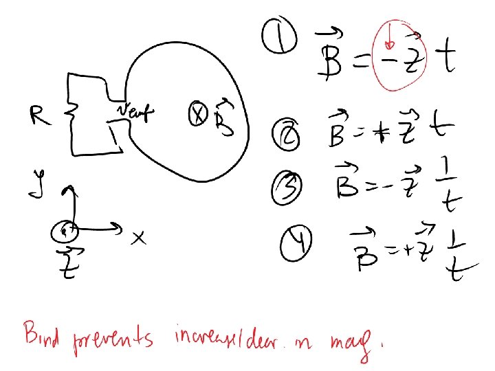
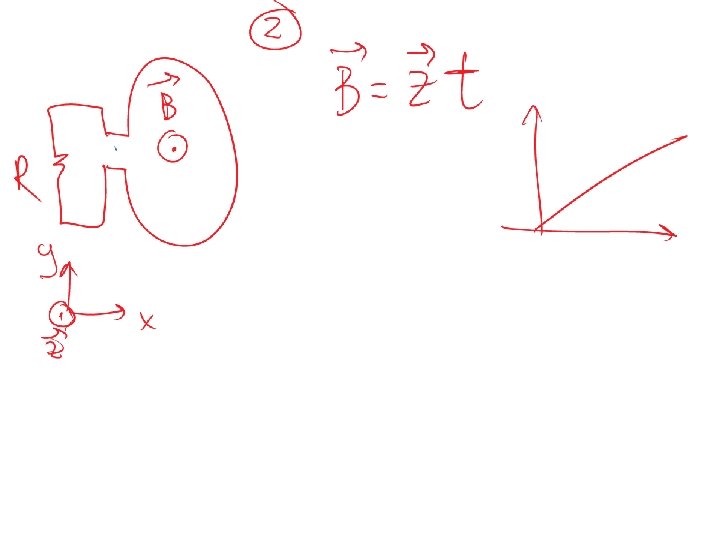
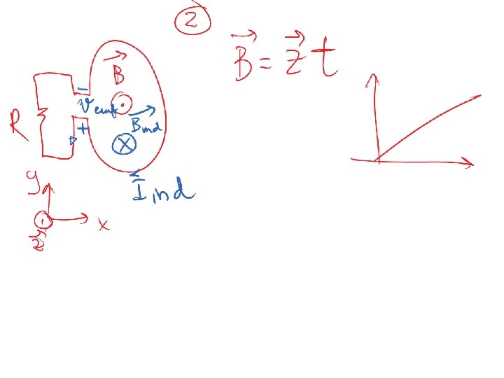
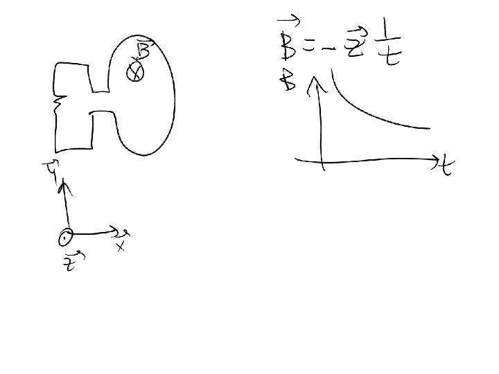
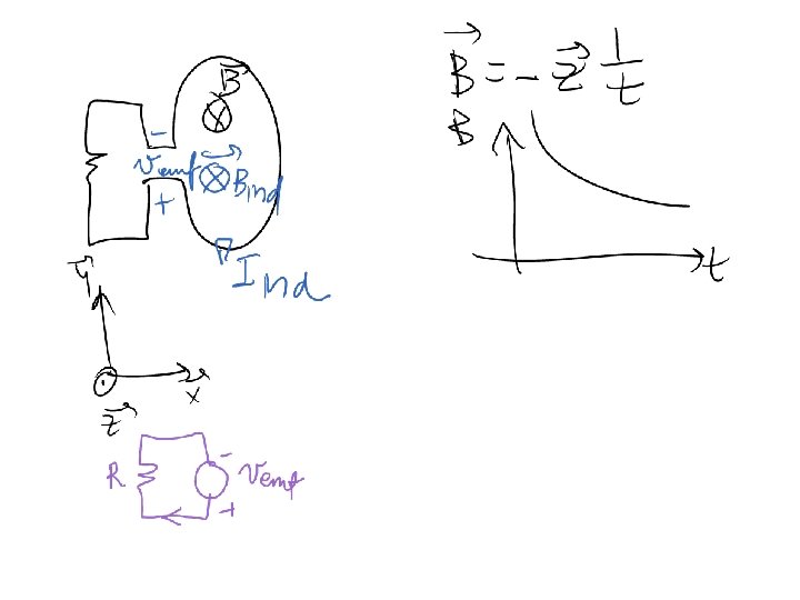
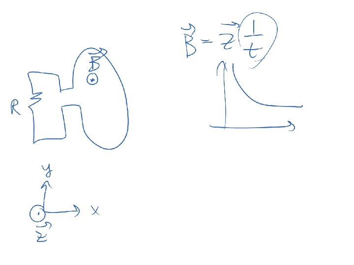
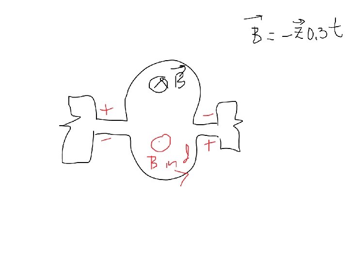
Guided Example, Lenz’s Law Find the direction of current in a circuit below, if magnetic flux density B is given.
1. Negative sign just gives you direction of field B 2. Magnitude of B is increasing with time 3. Current induced in the loop will oppose the change in field B 4. That induced current will have it’s own field B_ind 5. B_ind will be in such direction to prevent B from increasing 6. This means that B_ind will be in the z direction (opposite direction from B) 7. Use RHR to find the direction of I_ind
Stationary Loop in Time-Varying B
cont.
Example 6 -1 Solution
Ideal Transformer
Motional EMF Magnetic force on charge q moving with velocity u in a magnetic field B: This magnetic force is equivalent to the electrical force that would be exerted on the particle by the electric field Em given by This, in turn, induces a voltage difference between ends 1 and 2, with end 2 being at the higher potential. The induced voltage is called a motional emf
Motional EMF
Example 6 -3: Sliding Bar Note that B increases with x The length of the loop is related to u by x 0 = ut. Hence
Boundary Conditions