6 1 Functions of Formation Periods 2 FORMATION


 at the time of")


 Part-II Issued on - March")

- Slides: 41
6. 1 Functions of Formation Periods 2
FORMATION
Formation • The prepared flat surface or platform, which is ready to receive the ballast, sleepers, and rails, is called the formation. • It is important constituent of the track as it supports the entire track structure. • Formation consists of the layers comprising blanket, sub-grade , and embankment fill.
General Description of formation • Prepared either by doing additional earth work over the existing ground or by excavating existing surface and making cutting. • Can be either in the shape of embankment or a cutting. • Height of formation depends upon the ground contours and the gradient adopted. • The side slopes depends upon the shearing strength of soil. • The width of the formation depends upon the number of tracks to be laid & gauge of track.
Types of Formation • Embankment • Cutting
EMBANKMENT • That part of the Railway land where originally ground is low, subsequently raised by earth work to give the adjacent level which was decided during the survey. • Side slope of the embankment is 2: 1 (Horizontal : Vertical)
CUTTING • That part of the Railway land where originally ground is high, subsequently lowered by earth cutting to give the adjacent level which was decided during the survey. • Side slope of the cutting is 2: 1 or even steeper in case of rock. • Catch water drain to be provided in the top cutting wall and Side drain to be provided to the side of the track to ensure smooth flow of water.
Functions of Formation • To provide a smooth and uniform bed for laying the track. • To bear the load transmitted to it from the moving load through the ballast. • To facilitate drainage. • To provide stability to the track.
DISTRIBUTION OF STRESSES • From Rail wheel contact stresses of the order of 10, 000 Kg/cm 2 to Ballast blanket contact stresses of the order of 0. 5 Kg/cm 2 i. e. at the top of the formation • AIM – To have a formation which is able to take repetitive load without distress
Stress Distribution
Components of formation FORMATION TOP CESS TRACK STRUCTURE B A T L L A S BLANKET FORMATION SUB - GRADE SUB - SOIL TRACKFOUNDATION
• Track Foundation Constitutes ballast, sub-ballast, blanket and sub-grade, which is placed / exist below track structure to transmit load to subsoil. • Formation Top Boundary ( interface) between ballast and top of blanket or sub-grade (where blanket layer is not provided). • Formation-Width It is the distance between the edges of the prepared surface. • Cess Portion at top of formation level, extends from toe of ballast to edge of formation. • Ballast Crushed stones with desired specifications placed directly below the sleepers.
• Sub-Soil It is the soil immediately under the natural ground level. • Sub-Grade It is the upper part of embankment/cutting provided above subsoil by borrowed soil of suitable quality up to bottom of blanket/ballast. For embankment, sub-grade may be of imported soil whereas in cuttings it is the naturally occurring soil of sufficient strength. • Prepared Sub-grade The upper part of the sub-grade is formed into a prepared Sub-grade layer, which normally has a cross-fall. • Side-Slope It is the inclined surface of an embankment on cutting.
• Sub-ballast is a layer of coarse-grained material provided between blanket/sub-grade and ballast and confined to width of ballast section only. • To reduce the effect of loads transmitted to formation through ballast and • To guard against the possibility of ballast penetration into the formation. • It is desirable to provide a sub-ballast of 15 cm depth below the ballast layer. • The need to provide this sub-ballast may be decided by Chief Engineer (Const. ) in-charge of the project”.
• Blanket is a layer of specified coarse, granular material of designed thickness provided over full width of formation between sub-grade and ballast. • Blanket may be required over the formation where • The soil is of poor quality, • Rainfall is heavy and • Traffic density is high. • The absence of blanket in such cases can lead to problems in service, such as swelling or heaving of formation.
• Blanket Whether the blanket should be provided in a particular length and if so, its thickness (which should not be less than 30 cm) should be decided by the Chief Engineer (Const. ), in-charge of the project, duly taking into account the type of soil, rainfall and density of traffic and other factors relevant to the site conditions.
• Functions : A blanket/sub-ballast layer fulfil following important functions : • Primary Function : Stress Reduction Function - It reduces the traffic induced stresses on top of sub-grade to a tolerable limit. This function must be fulfilled to avoid track foundation failures. • Secondary Function : • Separation Function : It prevents penetration of ballast into sub-grade and also prevents upward migration of fine particles from subgrade into ballast.
• Drainage Function : It should intercept water coming from ballast away from sub-grade and at the same time, prevent drainage of water that is flowing upward from the sub-grade. • Prevention of Mud Pumping : It prevents mud pumping by checking attrition of sub-grade particles by ballast. The quality of blanket material should be such that it is able to carry out the above functions satisfactorily
Action for Smooth and uniform bed and to bear the load transmitted Preparation of Natural ground Compaction of filled up material
Action for Smooth and uniform bed and to bear the load transmitted Preparation of Natural ground Site should be cleared properly for full formation width at Ground level plus one metre. Then dressed and leveled. Depressions be filled with suitable soil duly compacted. Benching should be provided on ground having steep slope. In conversion/doubling, suitable benching of existing slope should be done to provide proper bonding between old and new earthworks.
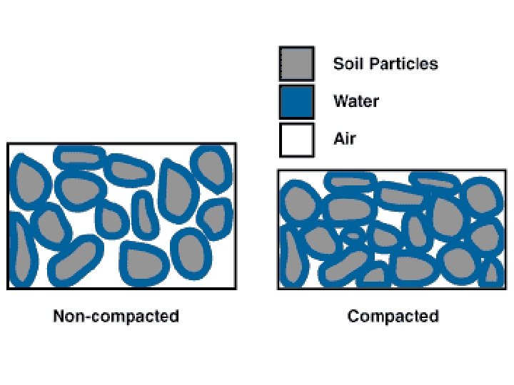
Action for Smooth and uniform bed and to bear the load transmitted Compaction To produce a soil mass with controlled or improved engineering properties. The water acts as lubricant and a closer packing of soil grains is obtained by the expulsion of air from the voids.
Compaction of filled up material • Process of increasing “Density of Soil” by mechanical means, by packing the soil particles closer together (by expelling air from the voids) to obtain a homogeneous soil mass having improved soil properties.
Factors affecting Compaction in Field § Compacting effort § Moisture control § Soil type § Thickness of layer § Number of passes § Compaction equipments
Compacting Effort • Types of machinery required are decided based on type of soil to be compacted. • Compaction is primarily of four types: • Static compaction, • Dynamic or Impact compaction • Vibratory compaction and, • Kneading compaction.
Moisture Control Maximum density with minimum compacting effort can be achieved by compaction of soil near its OMC (Optimum Moisture Content). Soil Type • Normally, clays and silts (fine grained soils) offer higher resistance to compaction. • Sandy soils or Gravelly soils (coarse grained soils) are amenable for easy compaction. • Coarse grained soils yield higher densities in comparison to clay. • A well-graded soil can be compacted to higher density.
Thickness of Layer • Depends upon type of soil involved and type of roller, its weight and contact pressure of its drums. • Decided on the basis of Field Compaction Trials. Normally, 200 – 300 mm is optimum in field for achieving homogenous compaction. Number of Roller Passes • Density of soil increases with the number of passes but after optimum number of passes, further increase in density is insignificant for additional number of passes. • Determined by Field Compaction Trials. Keep moisture content near OMC( OMC± 2%) at the time of compaction.
Moisture control Keep moisture content near OMC (OMC ± 2%) at the time of compaction. Compaction Equipments For Suitable type of Compaction Equipment, Number of Passes and Maximum thickness of Layers For different Type of Soils Refer to Annexure-4 of RDSO Guidelines GE: G-1 (July’ 2003)
Smooth Wheeled Rollers • Self-propelled or Towed, Weight 2 – 20 T. • Suitable for: Well Graded Sands and Gravels, Silts and Clays of low plasticity. • Unsuitable for: Uniform Sands, Silty Sands and Soft Clay.
Vibratory Roller • Range from “Hand guided” to “Larger roller”. • Suitable for: Most soils with low to moderate fines content. • Unsuitable for: Large volume of work and wet clayey soil.
Pneumatic Tyred Roller • Usually a container on two axles. • Wheels aligned to give a full-width rolled surface. • Dead loads added to give masses of 12 -40 T. • Suitable for: most coarse and fine soils. • Unsuitable for: very soft clay & highly variable soil.
Sheep Foot Roller • Also known as a 'tamping roller‘. • Self propelled or towed units, with hollow drum fitted with projecting club-shaped 'feet‘. • Weight: 5 -8 T. • Suitable for: fine grained soils/sands/gravels, with >20% fines. • Unsuitable for: very coarse soils & uniform gravels.
Impact Roller • Introduces energy to ground surface in succession, around two impacts per second. quick • By doing this in a rolling action at around 10 kmph, large areas can be treated quickly. • Useful for Bulk earthworks. Compacting in 1 m lifts up to 2 to 3 m depth at 10 kmph.
Grid Roller • Towed units with rolls of 30 -50 mm bars, with spaces between of 90 -100 mm. • Weight: 5 -12 T. • Suitable for: well-graded sands; soft rocks; stony soils with fine fractions. • Unsuitable for: uniform sands; silty sands; very soft clays.
Vibrating Plate for Slope Compaction § Range from “hand-guided” to “large machine”. § Suitable for: most soils with low to moderate fines content. § Unsuitable for: large volume work; wet clayey soils.
Slope Vibratory Roller § Available in weight of 5. 5 T to 17. 0 T § Drum width: 900 to 1300 mm § Vibrations: 1300 to 2000 vib/min
STABLE RAILWAY FORMATION • Stable formation – Should retain the track geometry under anticipated traffic densities and axle loads during service under most adverse conditions of operations and weather. • Should be structurally sound and the settlements should be within limits. 38
Function of effective Drainage ØRain water during monsoon is main enemy in damaging banks / cuttings So effective drainage is most important to safeguard formations from failure. ØFlow of water contaminate ballast, also erodes formations. It should not be allowed along the track. ØDrainage system should be efficient enough to prevent stagnation and allow quick disposal of water. ØEffectiveness depends on size of drain, permeability. 39
• • REFERENCE FOR MORE INFORMATION RDSO Guidelines for Earthwork in Railway Projects Guideline No: GE-1 July- 2003. RDSO Guidelines and Specifications for Design of Formation for Heavy Axle Load No. GE : 0014 Nov - 2009 RDSO Specification No: RDSO/2018/GE: IRS-004(D) Part-IV “ Rationalization of Formation layer thickness on Indian Railway Track – Issued on 25. 07. 2019. RDSO Specification No: RDSO/2018/GE: IRS-004(D) Part-I “ Specification of Non Woven Geo-textile to be issued as Separator/filtration in Railway Formation” – Issued on March 2019.
REFERENCE FOR MORE INFORMATION RDSO Specification No: RDSO/2018/GE: IRS-004(D) Part-II Issued on - March 2019. “Specification of Geo-composite Drain to be used at the base of Embankment” for Railway Formation. RDSO Specification No: RDSO/2018/GE: IRS-006 Issued on March 2019. “Specification of Geo-composite Drain to be used behind Bridge abutment/Retaining wall”. RDSO Specification No: RDSO/2018/GE: IRS-004(D) Part-III Issued on - February 2020. “Specification for Geo-grid to be used as Reinforcement/Stabilization for Railway Formation”. RDSO Specification No: RDSO/2007/GE: G-0008 Issued on February 2007. “ Guidelines for application of Jute Geotextile in Railway Embankments and Hill slopes ”.
Thank you