6 1 Configuration of sedimentation tank Sedimentation is


 Tube settlers and lamella plates")

 typical effluent structure")

 Finger weirs")
: Sludge zone")
- Slides: 13
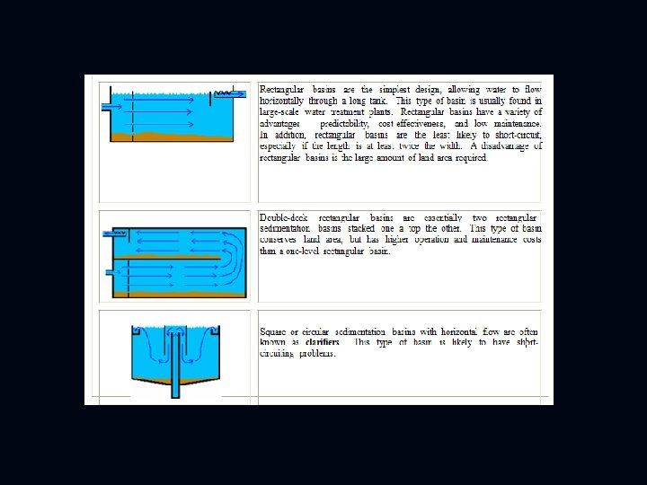
6. 1 Configuration of sedimentation tank Sedimentation is a treatment process in which the velocity of the water is lowered below the suspension velocity and the suspended particles settle out of the water due to gravity. The process is also known as settling or clarification. Three common types of sedimentation basins are shown below:
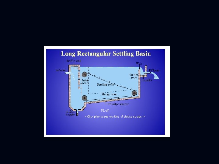
6. 2 Zones of sedimentation tank All sedimentation basins have four zones - the inlet zone, the settling zone, the sludge zone, and the outlet zone, as shown in fig (6. 1). Fig (6. 1) Zones of sedimentation tank
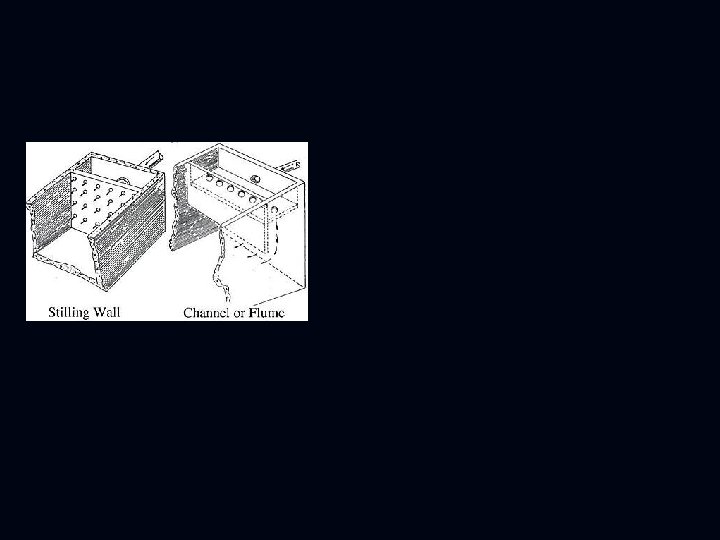
6. 2. 1 Inlet zone The two primary purposes of the inlet zone of a sedimentation basin are to distribute the water and to control the water velocity as it enters the tank. In addition, inlet devices act to prevent turbulence of the water. The incoming flow in a sedimentation basin must be evenly distributed across the width of the basin to prevent short-circuiting. Short-circuiting is a problematic circumstance in which water by passes the normal flow path through the tank and reaches the outlet in less than the normal detention time. Two types of inlets are shown below, fig (6. 2). The stilling wall, also known as a perforated baffle wall or diffusion wall, spans the entire tank from top to bottom and from side to side. Water leaves the inlet and enters the settling zone of the sedimentation basin by flowing through the holes evenly spaced across the stilling wall.
6. 2. 2 Settling zone After passing through the inlet zone, water enters the settling zone where water velocity is greatly reduced. This is where the bulk of flock settling occurs and this zone will make up the largest volume of the sedimentation tank. For optimal performance, the settling zone requires a slow, even flow of water. The settling zone may be simply a large expanse of open water. But in some cases, tube settlers and lamella plates, such as those shown in Fig. (6. 3), are included in the settling zone.
Fig (6. 3) Tube settlers and lamella plates
6. 2. 3 Outlet zone The outlet zone controls the water flow out of the sedimentation tank. Like the inlet zone, the outlet zone is designed to prevent short-circuiting of water in the basin. In addition, a good outlet will ensure that only well settled water leaves the tank. The outlet can also be used to control the water level in the basin. Outlets are ion that the water flow out to ensure designed of minimum amount of flock suspended in it. The best quality water is usually found at the very top of the sedimentation basin, so outlets are usually designed to skim this water off the sedimentation tank. A typical outlet zone begins with a baffle in front of the effluent. This baffle prevents floating material from escaping the sedimentation tank. After the baffle comes the effluent structure, which usually consists of a launder, weirs, and effluent piping. A typical effluent structure is shown in Fig. (6. 4)
Fig (6. 4) typical effluent structure
The primary component of the effluent structure is the effluent launder, a trough which collects the water flowing out of the sedimentation tank and directs it to the effluent piping. The sides of a launder typically have weirs attached. Weirs are walls preventing water from flowing uncontrolled into the launder. Weirs serve to skim the water evenly off the tank. A weir usually has notches, holes, or slits along its length. These holes allow water to flow into the weir. The most common type of hole is the V-shaped notch shown on the figure above which allows only the top inch or so of water to flow out of the sedimentation basin. Conversely, the weir may have slits cut vertically along its length, an arrangement which allows for more variation of operational water level in the sedimentation basin. Water flows over or through the holes in the weirs and into the launder. Then the launder channels the water to the outlet, or effluent pipe. This pipe carries water away from the sedimentation tank and to the next step in the treatment process. The effluent structure may be located at the end of a rectangular sedimentation tank or around the edges of a circular clarifier. Alternatively, the effluent may consist of finger weirs, an arrangement of launders which extend out into the settling tank as
Fig. (6. 5) Finger weirs
Fig. (6. 6): Sludge zone