5 BRIDGES TRACK STRUCTURE ON BRIDGES 5 1

5 BRIDGES & TRACK STRUCTURE ON BRIDGES 5. 1 Bridges: Classification, Types, Track Structure on girder Bridges ballasted decks, arch bridges, provision of guard rails, rerailing ramps. (PERIODS 1)

CLASSIFICATION & TYPES OF RAILWAY BRIDGES

STATISTICS OF BRIDGES ON INDIAN RAILWAYS

GAUGEWISE, ROUTEWISE No. OF BRIDGES CLASSFIED AS IMP, MAJOR AND MINOR BRIDGES Gauge Route TYPE OF BRIDGE Total Important Major Minor A 177 1629 17290 19096 B 193 3054 30248 33495 C 8 166 1543 1717 D-Spl 71 983 13147 14201 D 106 2371 24610 27087 E 118 3212 38391 41721 Total 673 11415 125229 137317 MG 23 405 4911 5339 NG 4 265 4598 4867 700 12085 134738 147523 BG Grand Total

No. OF BRIDGES TYPE WISE Type of Bridge Triangulated Girder RSJ/ Plate Girder Nos. 864 8863 Composite Girder 286 PSC Girder 2282 RCC Girder 662 PSC Slab RCC Slab 11405 34198 TOTAL = 147523 Type of Bridge RCC Box Culvert Arch Bridge Rail openings Timber top bridges Stone slab bridges Other type Nos. 32735 17939 912 32 5338 32007

No. OF BRIDGES AGEWISE TYPE OF BRIDGE IMPORTA NT MAJOR 100 YEAR+ 242 80 YEARS+ 286 60 YEARS+ 327 3009 3868 4557 MINOR 34438 46475 56832 TOTAL 37689 50629 61716
 Superstructure – Track Structure – Girder – Bearing 2)")
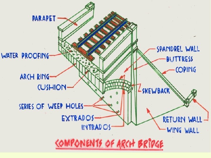
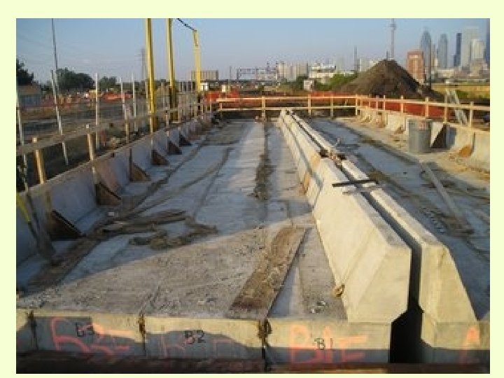
MAIN ELEMENTS OF BRIDGE 1) Superstructure – Track Structure – Girder – Bearing 2) Substructure – Bed Block – Pier/Abutment/Wing Wall 3) Foundations 4)Training & Protective Works Monolithic Bridge Like Pipe Culvert, Box Culvert and Arch Act like one unit.

CLASSIFICATION OF BRIDGES • CRITERIA FOR CASSIFICATION • ACCORDING TO SPAN/OPENING • ACCORDING TO FUNCTION. • ACORDING TO MATERIAL OF CONSTRUCTION IN SUPER STRUCTURE. • ACCORDING TO FORM OR TYPE OF SUPERSTRUCTURE. • ACCORDING TO LEVEL OF FLOOR SYSTEM. • ACCORDING TO TYPE OF SERVICE. • ACCORDING TO METHOD OF CONNECTIONS. • ACCORDING TO DECKING WITH REF. TO HFL. • ACCORDING TO GAUGE. • ACCORDING TO LOADING STANDARD.
 (A)IMPORTANT BRIDGE: Important bridges are those")
ACCORDING TO SPAN OR OPENING (PARA 1103 IRBM) (A)IMPORTANT BRIDGE: Important bridges are those having a linear waterway of 300 meters or a total waterway of 1000 Sqm or more and those classified as important by the Chief Engineer / Chief Bridge Engineer, depending on considerations such as depth of waterway, extent of river training works and maintenance problems. (B)MAJOR BRIDGE : A major bridge is one which has a total water way of 18 linear meters or more or which has a clear opening of 12 linear meters or more in any one span. (C)MINOR BRIDGES: Bridges which do not fall in these classifications are termed as minor bridges.
Track Bridge (for Rail vehicle) – Over water bodies i. e")
ACCORDING TO FUNCTION 1)Track Bridge (for Rail vehicle) – Over water bodies i. e River/ Nallah /Canal Balancing culverts – Over Valley (viaduct) – Over Railway (Fly-over) – Under Railway (RUR) – Over Road (RUB) 2) Road Bridge (For Road Vehicle) – Over Railway (ROB)
 Rail cum road bridge – Over river 4) Foot over Bridge (For pedestrian)")
3) Rail cum road bridge – Over river 4) Foot over Bridge (For pedestrian) – Over Railway (On platform for public) – Foot Under bridge (Subways) 5) Pipe Line Bridge - Over Railway 6) Aquaduct - Canal or Nallah over Track 7) Siphon
 Timber Bridge (obsolete) 2) Masonry")
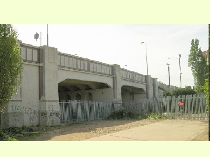
ACCORDING TO MATERIAL OF CONSTRUCTION OF SUPER STRUCTURE 1) Timber Bridge (obsolete) 2) Masonry Arch – Stone & Brick – In lime Mortar & Cement Mortar respectively 3) Steel Bridge – Riveted Fabrication – Welded Fabrication 4) RCC Bridge 5) Pre-stressed Concrete Bridge 6) Composite (Steel & Concrete) Bridge
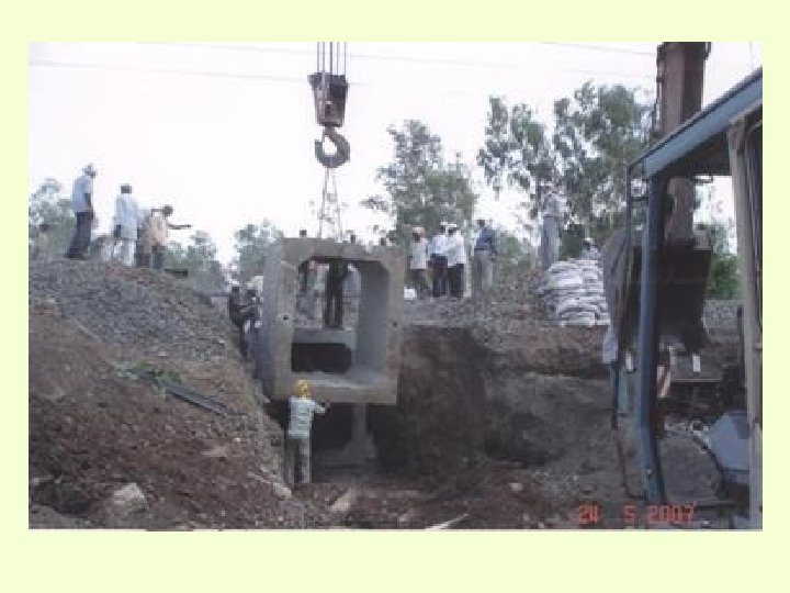
 Pipe Culvert 2) RCC Slab 3)")
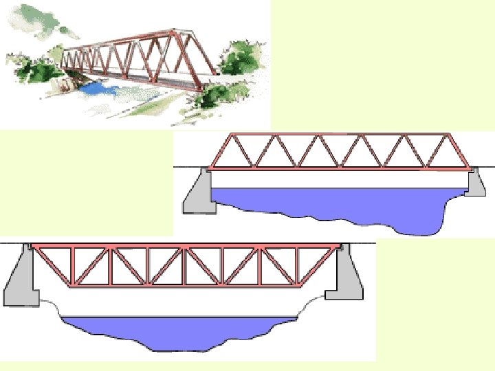
ACCORDING TO FORM OR TYPE OF SUPERSTRUCTURE 1) Pipe Culvert 2) RCC Slab 3) Rail opening (Only on branch line) 4) Rail Cluster (Only on branch line) 5) RCC Box Culvert 6) Steel Plate Girder 7) Steel Open Web Girder 8) Arch Bridge
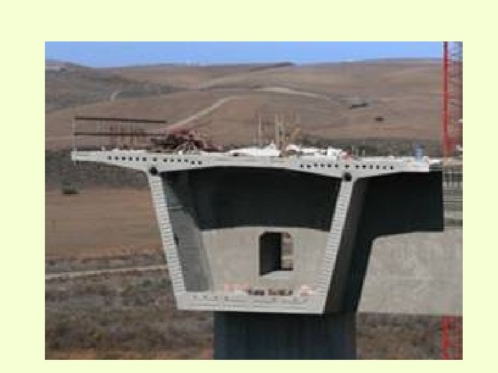
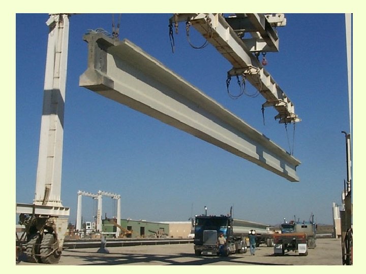
 RCC/PSC ‘T” or “I” Beam Bridge 10) RCC/PSC Box Girder 11) Suspension Bridge")
9) RCC/PSC ‘T” or “I” Beam Bridge 10) RCC/PSC Box Girder 11) Suspension Bridge 12) Cable Stayed Bridge 13) Bow String Bridge

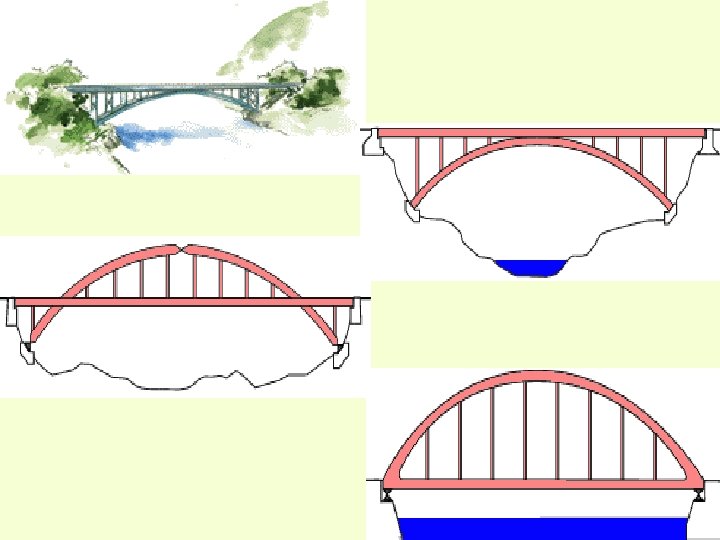
Arch Bridge

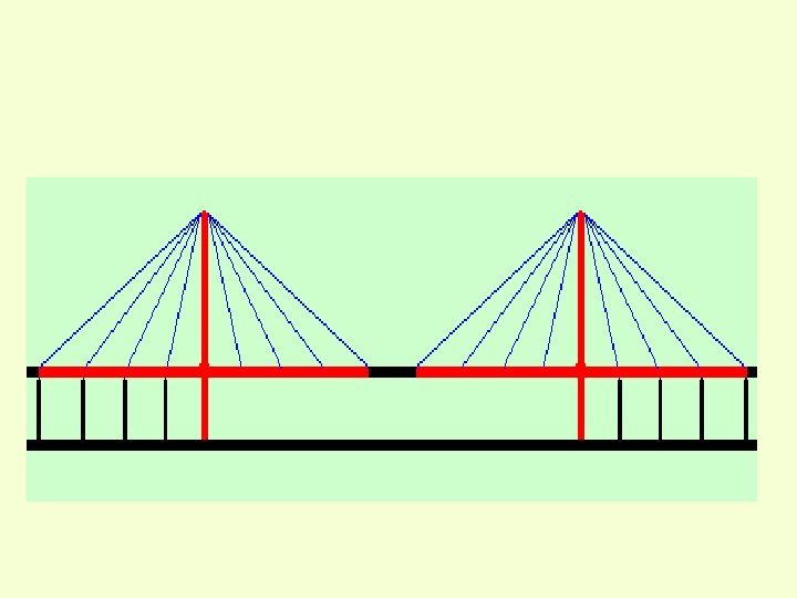
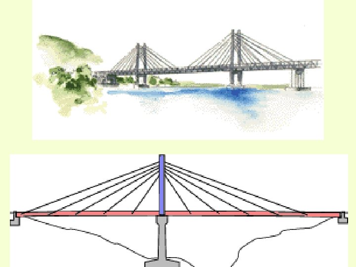
Cable Stayed Bridge
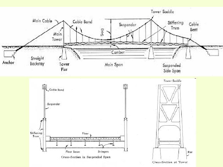
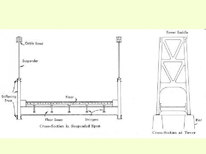

Suspension Bridge: Forces
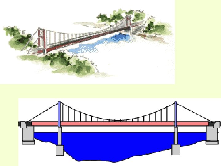

Suspension Bridge
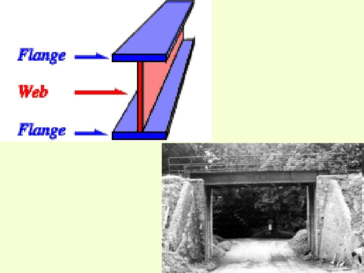

PLATE GIRDER ELEVATION

PLATE GIRDER CROSS PLAN

PLATE GIRDER CROSS SECTION
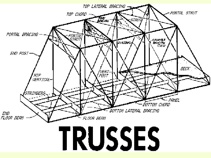
 Deck Type – (Track Structure on Top")
ACCORDING TO LEVEL OF FLOOR SYSTEMS 1) Deck Type – (Track Structure on Top Flange or Chord) 2) Through Type (Track structure Floor System Connected to Bottom Chord Panel) 3) Semi Through Type (Track Structure Floor System Connected to Web and no top Bracings)

SEMI THROUGH TRUSS

Warren Trusses

K-Truss

OPEN WEB THROUGH SPAN ELEVATION

TOP PLAN

PLAN AT FLOOR LAVEL

Beam Bridge

MOVEABLE BRIDGES • Swing Bridge • Bascule Bridge • Lifting Bridge

Bascule Bridges

Swing Bridges

Lifting bridges
 Permanent 2) Temporary – Restricted Head Girder (RH")
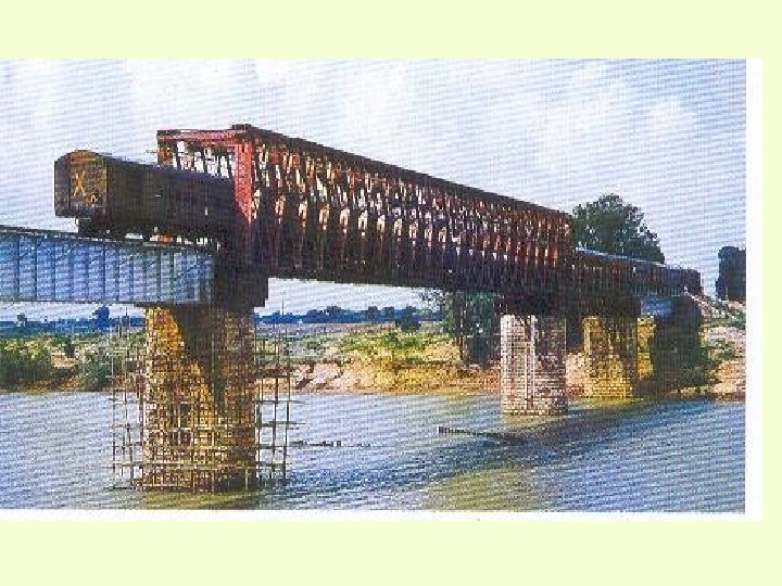
ACCORDING TO TYPE OF SERVICE 1) Permanent 2) Temporary – Restricted Head Girder (RH Girder) – Callender-Hamilton Bridge – Pantoon Bridge

Pontoon Bridges
 1 RH Girder (Plate")
Type of girder 1. Rail Cluster Span 3660 mm (12’) 1 RH Girder (Plate girder type, duplicate girders) a)1800 mm b)7200 mm (24’) c)9680 mm(31’-9”) d)13200 mm (44”) e)16400 mm (53’-6”) f)26480 mm (87”) 2. Calendar Hamilton Girder(open web through type) a)24400 mm (80’) b)30500 mm (100’) c)45700 mm (150’) d)61000 mm (200’) 4. Standard Span (Plate girders) a)12200 mm (40’) b)18300 mm (60’) c)24400 mm (80’)
 1) Riveted 2) Welded 3) Bolted")
ACCORDING TO METHOD OF CONNECTION (STEEL GIRDER) 1) Riveted 2) Welded 3) Bolted
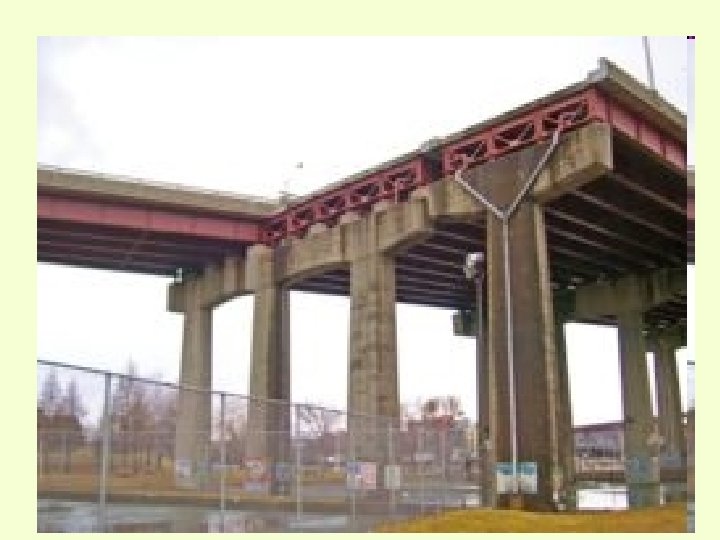
 High Level bridge 2)")
ACCORDING TO LEVEL OF DECKING WITH REFERENCE TO HFL 1) High Level bridge 2) Causeway or Irish Bridge 3) Siphon Bridge
 Important bridges are those having a")
ACCORDING TO SPAN OR OPENING Para-1103 3. (a) Important bridges are those having a linear waterway of 300 metres or a total waterway of 1000 Sqm or more and those classified as important by the Chief Engineer / Chief Bridge Engineer, depending on considerations such as depth of waterway, extent of river training works and maintenance problems. b) A major bridge is one which has a total water way of 18 linear metres or more or which has a clear opening of 12 linear metres or more in any one span. c) Bridges which do not fall in these classifications are termed as minor bridges.
 Minor Bridge – Clear opening < 12 m")
ACCORDING TO SPAN OR OPENING-Para-1103 1) Minor Bridge – Clear opening < 12 m or Total Lineal Waterway< 18 m ( FOR MULTIPLE SPAN) 2) Major Bridge – Clear opening ≥ 12 M or Total Lineal Waterway ≥ 18 M 3) Important Bridges – – Total Lineal waterway 300 M OR – Total Waterway 1000 M 2 OR – Those classified as ‘IMPORTANT BY CE/CBE due to their depth of W. Way, Extent of River Training Works & Past History Maintenance Problem.
 Broad Gauge (BG – 1676 MM) 2) Metre Gauge")
ACCORDING TO RAILWAY GAUGE 1) Broad Gauge (BG – 1676 MM) 2) Metre Gauge (MG – 1000 MM) 3) Narrow Gauge (NG – 762 MM)
 – MBG")
ACCORDING TO LOADING STANDARD Broad Gauge – DFC – 25 T (2008) – MBG – 1987 (Modified Broad Gauge) – RBG – 1975 (Revised Broad Gauge) – BGML (Main Line) – BGBL (Branch Line)

TRACK STRUCTURE on GIRDER BRIDGES & GUARD RAILS

Rail and rail joints • Longitudinal profile of rails. • Rail cant. • Rail joints over the bridgea) Small bridges having opening < 6. 1 m rail joint should be avoided. b) For other spans, the preferred position is at 1/3 the span from the ends. c) Rail joint should be avoided within 3 m from abutment.

SWR on bridges • SWR may be continued over girder bridges with un-ballasted decks up to 13. 3 m opening if symmetrical. • In case of asymmetrical up to 6. 1 m opening. • If SWR is laid, no fish plated joint should be located on the girder or within 6 m from abutment • 26 m long rolled rails may also be provided.

LWR on bridges • LWR can be continued over ballasted deck bridges without bearings like slabs, box culverts and arches. • LWR / welded panel can be laid over bridges with / without ballasted deck are as follows: 1. Bridges provided with rail free fastenings (single span not exceeding 30. 5 m and having sliding bearings on both sides). 2. Bridges provided with rail free fastenings and partly box anchored (single span not exceeding 30. 5 m and having sliding bearings on both sides).

3. Welded rails may be provided from pier to pier with rail free fastening and box anchoring as per the case with SEJ on each pier. 4. LWR / CWR may be continued over a bridge with the provision of SEJ at the far end approach at 10 m from abutment. 5. Welded panel may be provided over a single span bridge with rail free fastenings and box anchoring as per the case with SEJ at 30 m from abutment.

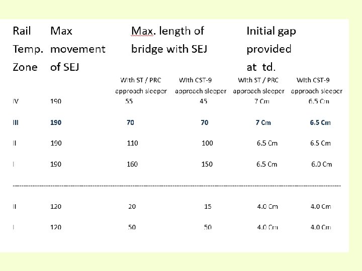
Table -1 Maximum overall length of bridges permitted on LWR / CWR on BG Temperat Rail ure section Zones Rail free fastening (PRC/ST) in approaches Rail free fastening and partly box anchored (PRC/ST) in approaches I 60 Kg 52 Kg / 90 R 30 45 77 90 II 60 Kg 52 Kg / 90 R 11 27 42 58 III 60 Kg 52 Kg / 90 R 11 27 23 43 IV 60 Kg 52 Kg / 90 R 11 27 23 43

Length of single span bridge permitted temperature zone-wise

Precautions for arresting creep. • Track laid with standard single rails and fish plated joints be isolated with SWR if laid on approaches by providing two well anchored standard rail lengths. • Track laid with standard single rails and fish plated joints be isolated with LWR if laid on approaches by providing 36 m well anchored SWR on either side.

Provision of guard rails • Should be provided on all girder bridges. • Should be provided on Prestressed concrete girder bridges without deck slab. • Should be provided on all major and important ballasted bridges and also on such minor bridges where derailment may cause serious damages. • On all flat top, arch and Prestressed concrete girder bridges with deck slab where guard rail is not provided the whole width of the bridge between parapet walls shall be filled with ballast up to sleeper level.

Design of guard rail

Splaying of guard rail • In the case of through girder bridges on double lines, guard rails should be splayed on either ends. • Other than through bridges splaying be done only on the facing direction. • However the non splayed end should be bent downwards after it is stopped at the end of the abutment and wooden block provided.

Trolley refuse • Bridges with span < 100 m at 100 m. • Bridges with span > 100 m on each pier.

Hook Bolt • Hook bolts tie the sleeper with girder flange. • The lips of the hook bolts will be as per the design of the girder. • Hook bolts are of 22 mm dia with square shank.

Inspection and maintenance of track on approaches. • On bridge approaches, sleepers with arrangement for fixing guard rail should be provided. • Full complement of track fittings on approaches up to 100 m. • Rail level should be maintained and dip immediately after abutment should be avoided.

Continued. . • Rail joint should be avoided within 3 m from abutment. • Joggle plating of AT welds if length of water way is ≥ 100 m and on approaches upto 100 m.

Continued. . For important and major bridges: • In case of CST-9 or wooden on approaches, PRC / ST with ERC should be provided up to 100 m / up to full breathing length where ever LWR is provided on approach of bridge. • 90 cm cess width should be provided up to 100 m on approaches.

Inspection and maintenance of track on bridges. • It should be ascertained whether it is central on the rail bearers and the main girders and in good line and level. • The condition of sleepers, spacing and squareness should be checked.

Continued. . • Rail fastenings should be tight. • Condition of path way. • Sand bins should always be filled with dry and loose sand.

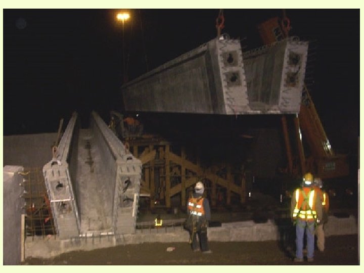
Re-railing Ramps.

Re-railing Ramps. Derailment-though undesirable, but inescapable event do take place over the rail track. On plain track, the aftermath will be less as compared to a major bridge. The unfavorable rail wheel induction forces cause derailment. If, a suitable mechanism is established at appropriate place will not only brings back the wheel but also safeguards the precious bridges structures of the railways. A re-railing ramp is such a mechanism developed to mitigate the problem and thus brings back the derailed wheel on to the track.
")
Re-railing Ramps. (RDSO Drg for re-railing ramps sleepers)
")
Re-railing Ramps: (overall assembly )

Thank you
- Slides: 85