
5 BALLAST 5 3Specification for track ballast measurement
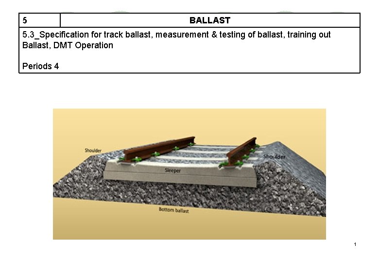
5 BALLAST 5. 3_Specification for track ballast, measurement & testing of ballast, training out Ballast, DMT Operation Periods 4 1
Requirements of Track Ballast l Tough and wear resistant l Hard without getting crushed under moving loads l Generally cubical having sharp edge (Angular) l Non-porous and non-absorbent of water 2
Requirements of Track Ballast l Resist Attrition l Durable and should not get pulverized under weather condition l Good drainage of water l Economical in cost 3

Stress Distribution 4
Ballast Fouling Potential sources are l Ballast breakdown 1. 2. 3. 4. Handling Tamping/packing Traffic Weathering 5 CONTD. .

Ballast Fouling l Fines from subgrade 1. Mud pumping 2. Seepage l Fines from surface 1. Droppings from trains 2. Wind or water transported 3. Open defectation and garbage dumping in city limits by adjoining slum area. 6
Effects of Fouling l Impedes drainage l Affects elasticity of ballast & track modulus l Tamping/ packing becomes difficult l Increases dynamic loads (impact factor) l Reduces electrical resistance 7
Remedial measures - fouling l Shoulder screening : Preventive maintenance – Once in 3 yrs. l Deep Screening : Breakdown maintenance – Once in 10 yrs. l Deep Screening of track shall be done after 500 GMT or 10 years, whichever is earlier, or if clean cushion is less than 150 mm. (ACS 132) 8
Track Ballast 1. 2. 3. 4. Ballast may be subdivided into following zones: Crib Shoulder Top Ballast Bottom Ballast 9

Parameters for determination of Standard of Ballast Physical parameters i) Specific Gravity General Requirement More mass Functional Requirement More mass helps in resisting lateral forces. ii) Structure ii. a) Shape b) Grading For compaction, interlocking & internal friction Round ballast cannot be compacted Helps enhanced retentivity Cubical shape iii. Uniformly graded i) Optimum voids for resilience and drainage ii) Longevity is controlled by the voids available to accommodate fines.

Parameters for determination of Standard of Ballast Physical parameters c) Size iii) Texture General Requirement Functional Requirement Larger size (>50 mm) Small percentage is tolerable; otherwise settlement properties gets adversely affected. Smaller size (<40 mm) Small percentage is required for correcting track geometry defects during maintenance. Optimum size (40 to 50 mm) This range of particle size gives least settlement. a)Elongation Index b) Flakiness Index As low as possible; flaky and elongated ballast is unstable and lacks locking properties.
Parameters for determination of Standard of Ballast Mechanical parameters i) Hardness Resistance to abrasion/attrition, required for least damage / breakage during maintenance. This is measured by Los Angels Abrasion value. ii) Toughness Resistance to fracture under impact loads. This is measured by Impact Value. iii) Water absorption This should be checked to ensure higher resistance to weathering during adverse weather conditions. 12
Parameters for determination of Standard of Ballast Chemical parameters: i) Inertness This should be checked to ensure that ballast is chemically inert and inactive from decomposition. 13
Flakiness Index l The flakiness index of an aggregate is the percentage by weight of particles in it whose least dimension (thickness) is less than threefifths(60%) of their mean dimension 14
Elongation Index l The elongation index of an aggregate is the percentage by weight of particles in it whose greatest dimension (length) is greater than one and four-fifth times (1. 8 times) their mean dimension 15
DETAILED SPECIFICATIONS IRS GE – 1 JULY 2016 l Basic Quality: Ballast should be hard, durable and as far as possible angular along edges/corners, free from weathered portions of parent rock, organic impurities and inorganic residues. l Particle Shape: Ballast should be cubical in shape as far as possible. Individual pieces should not be flaky and should have generally flat faces with not more than two rounded/sub rounded faces. 16
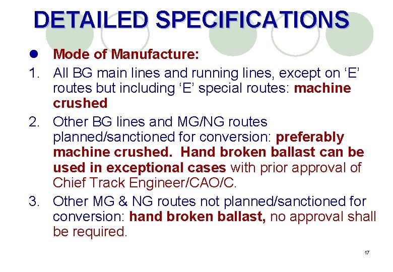
DETAILED SPECIFICATIONS l Mode of Manufacture: 1. All BG main lines and running lines, except on ‘E’ routes but including ‘E’ special routes: machine crushed 2. Other BG lines and MG/NG routes planned/sanctioned for conversion: preferably machine crushed. Hand broken ballast can be used in exceptional cases with prior approval of Chief Track Engineer/CAO/C. 3. Other MG & NG routes not planned/sanctioned for conversion: hand broken ballast, no approval shall be required. 17
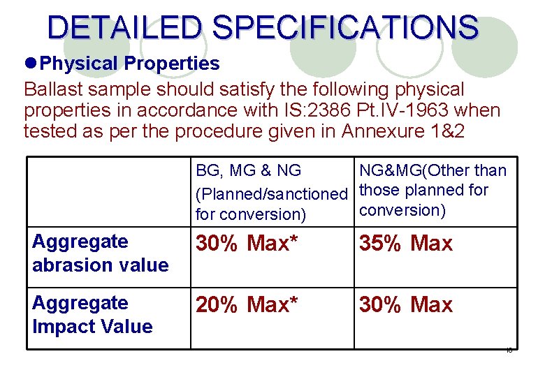
DETAILED SPECIFICATIONS l. Physical Properties Ballast sample should satisfy the following physical properties in accordance with IS: 2386 Pt. IV-1963 when tested as per the procedure given in Annexure 1&2 BG, MG & NG NG&MG(Other than (Planned/sanctioned those planned for conversion) Aggregate abrasion value 30% Max* 35% Max Aggregate Impact Value 20% Max* 30% Max 18
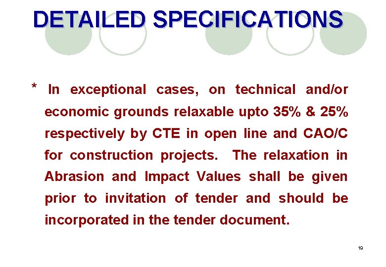
DETAILED SPECIFICATIONS * In exceptional cases, on technical and/or economic grounds relaxable upto 35% & 25% respectively by CTE in open line and CAO/C for construction projects. The relaxation in Abrasion and Impact Values shall be given prior to invitation of tender and should be incorporated in the tender document. 19
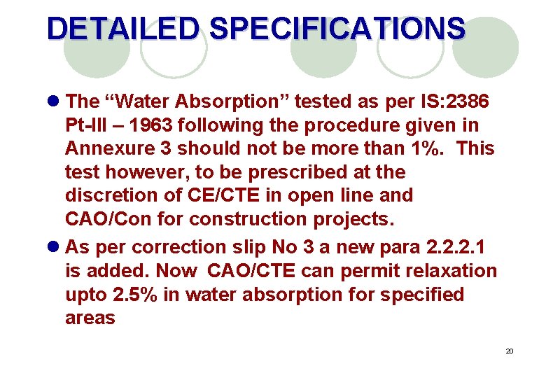
DETAILED SPECIFICATIONS l The “Water Absorption” tested as per IS: 2386 Pt-III – 1963 following the procedure given in Annexure 3 should not be more than 1%. This test however, to be prescribed at the discretion of CE/CTE in open line and CAO/Con for construction projects. l As per correction slip No 3 a new para 2. 2. 2. 1 is added. Now CAO/CTE can permit relaxation upto 2. 5% in water absorption for specified areas 20
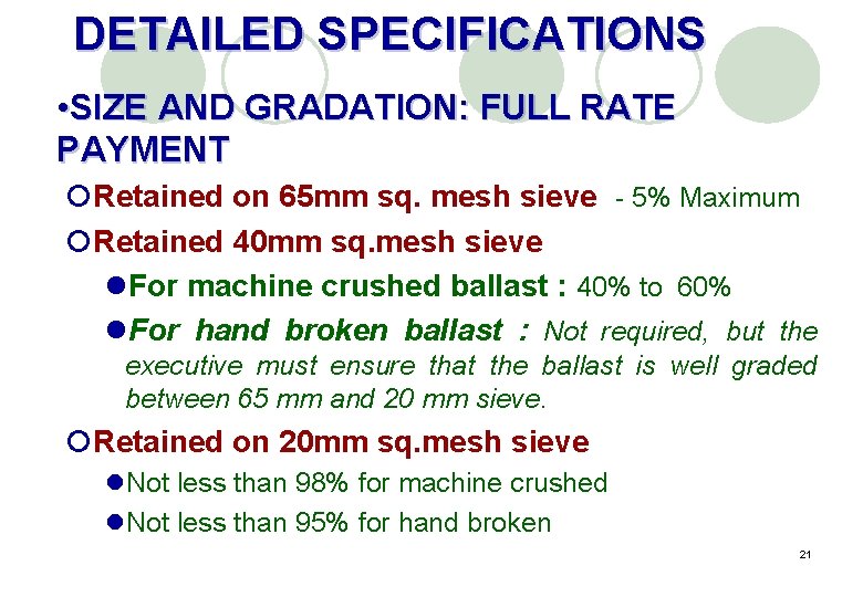
DETAILED SPECIFICATIONS • SIZE AND GRADATION: FULL RATE PAYMENT ¡Retained on 65 mm sq. mesh sieve - 5% Maximum ¡Retained 40 mm sq. mesh sieve l. For machine crushed ballast : 40% to 60% l. For hand broken ballast : Not required, but the executive must ensure that the ballast is well graded between 65 mm and 20 mm sieve. ¡Retained on 20 mm sq. mesh sieve l. Not less than 98% for machine crushed l. Not less than 95% for hand broken 21
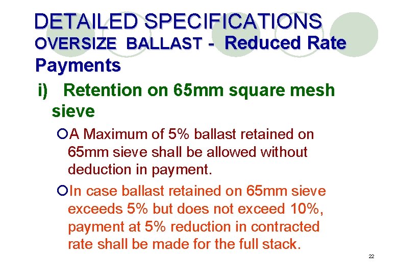
DETAILED SPECIFICATIONS OVERSIZE BALLAST - Reduced Rate Payments i) Retention on 65 mm square mesh sieve ¡A Maximum of 5% ballast retained on 65 mm sieve shall be allowed without deduction in payment. ¡In case ballast retained on 65 mm sieve exceeds 5% but does not exceed 10%, payment at 5% reduction in contracted rate shall be made for the full stack. 22
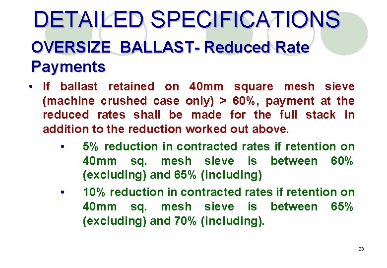
DETAILED SPECIFICATIONS OVERSIZE BALLAST- Reduced Rate Payments • If ballast retained on 40 mm square mesh sieve (machine crushed case only) > 60%, payment at the reduced rates shall be made for the full stack in addition to the reduction worked out above. • 5% reduction in contracted rates if retention on 40 mm sq. mesh sieve is between 60% (excluding) and 65% (including) • 10% reduction in contracted rates if retention on 40 mm sq. mesh sieve is between 65% (excluding) and 70% (including). 23
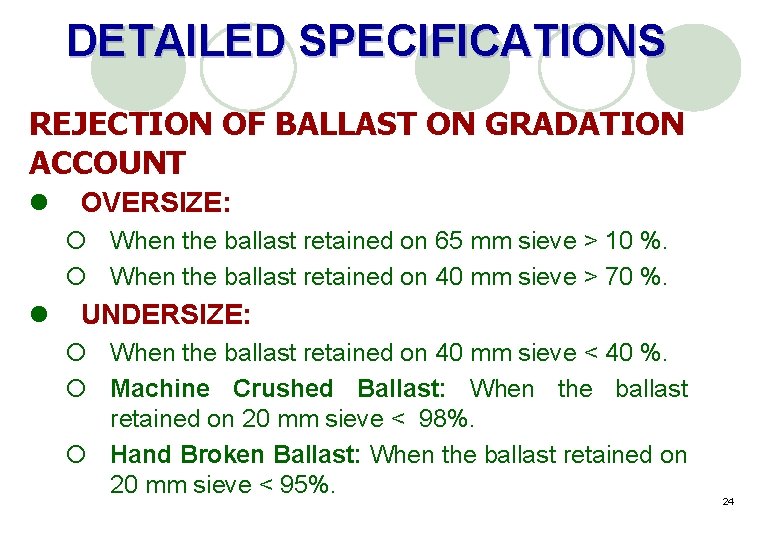
DETAILED SPECIFICATIONS REJECTION OF BALLAST ON GRADATION ACCOUNT l OVERSIZE: ¡ When the ballast retained on 65 mm sieve > 10 %. ¡ When the ballast retained on 40 mm sieve > 70 %. l UNDERSIZE: ¡ When the ballast retained on 40 mm sieve < 40 %. ¡ Machine Crushed Ballast: When the ballast retained on 20 mm sieve < 98%. ¡ Hand Broken Ballast: When the ballast retained on 20 mm sieve < 95%. 24
DETAILED SPECIFICATIONS METHOD OF SIEVE ANALYSIS • • Sieve sizes are nominal sizes. The following tolerances shall be permitted: 65 mm square mesh sieve Plus minus 1. 5 mm 40 mm Square Mesh Sieve Plus Minus 1. 5 mm 20 mm Square Mesh Sieve Plus Minus 1. 0 mm Mesh size of the sieves should be checked before actual measurement. The screen shall not be less than 100 cm in length, 70 cm in breadth and 10 cm in height on sides. 25
l Plate Thickness ¡ 65 mm = 3 mm (+1. 0 mm, -0. 5 mm) ¡ 40 mm = 2 mm (± 0. 5 mm) ¡ 20 mm = 2 mm (± 0. 5 mm) l Pitch of Square Holes of the Sieve ¡ 65 mm = 80 mm (+12 mm, -8. 0 mm) ¡ 40 mm = 50 mm (+7. 5 mm, -5. 0 mm) ¡ 20 mm = 25 mm (+4. 0 mm, -2. 5 mm) 26
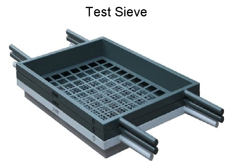
Test Sieve
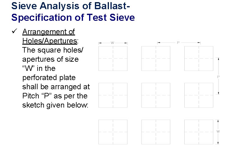
Sieve Analysis of Ballast- Specification of Test Sieve ü Arrangement of Holes/Apertures: The square holes/ apertures of size “W” in the perforated plate shall be arranged at Pitch “P” as per the sketch given below:
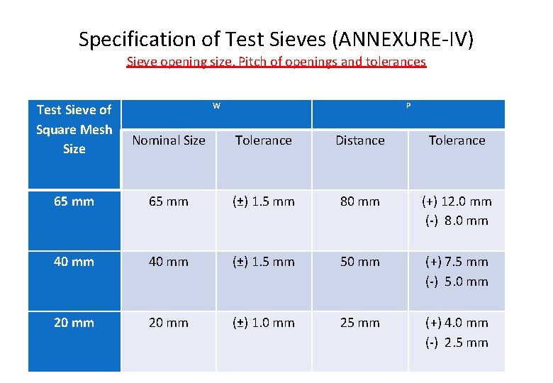
Specification of Test Sieves (ANNEXURE-IV) Sieve opening size, Pitch of openings and tolerances Test Sieve of Square Mesh Size W P Nominal Size Tolerance Distance Tolerance 65 mm (±) 1. 5 mm 80 mm (+) 12. 0 mm (-) 8. 0 mm 40 mm (±) 1. 5 mm 50 mm (+) 7. 5 mm (-) 5. 0 mm 20 mm (±) 1. 0 mm 25 mm (+) 4. 0 mm (-) 2. 5 mm
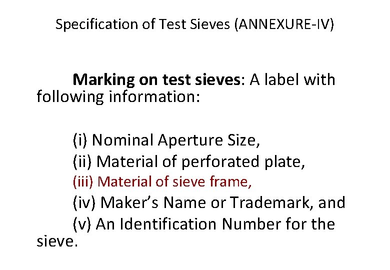
Specification of Test Sieves (ANNEXURE-IV) Marking on test sieves: A label with following information: (i) Nominal Aperture Size, (ii) Material of perforated plate, (iii) Material of sieve frame, (iv) Maker’s Name or Trademark, and (v) An Identification Number for the sieve.
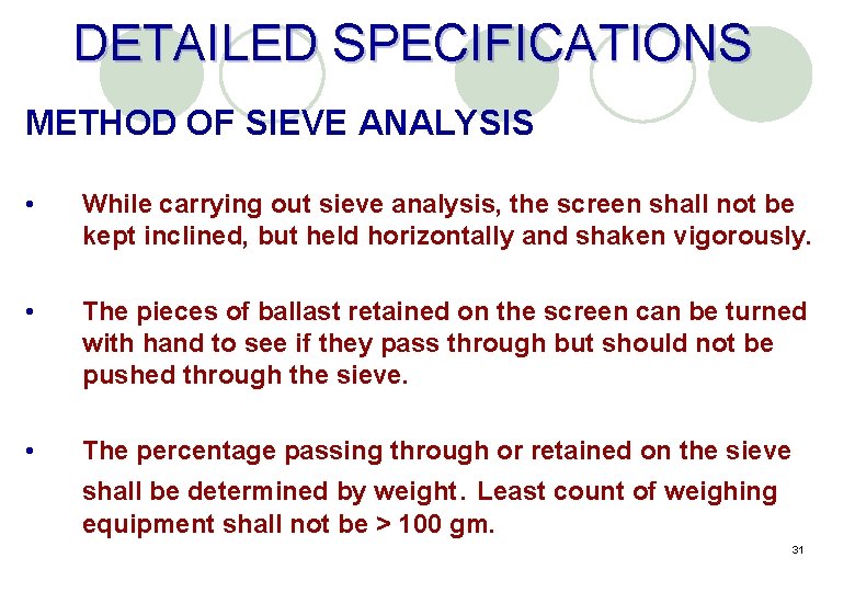
DETAILED SPECIFICATIONS METHOD OF SIEVE ANALYSIS • While carrying out sieve analysis, the screen shall not be kept inclined, but held horizontally and shaken vigorously. • The pieces of ballast retained on the screen can be turned with hand to see if they pass through but should not be pushed through the sieve. • The percentage passing through or retained on the sieve shall be determined by weight. Least count of weighing equipment shall not be > 100 gm. 31
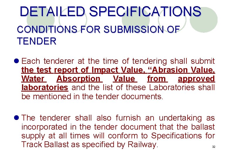
DETAILED SPECIFICATIONS CONDITIONS FOR SUBMISSION OF TENDER l Each tenderer at the time of tendering shall submit the test report of Impact Value, “Abrasion Value, Water Absorption Value from approved laboratories and the list of these Laboratories shall be mentioned in the tender documents. l The tenderer shall also furnish an undertaking as incorporated in the tender document that the ballast supply at all times will conform to Specifications for Track Ballast as specified by Railway. 32
DETAILED SPECIFICATIONS STACK MEASUREMENT l Stacking on a neat, plain, firm and well drained ground (to be done by railway) l The height of stack shall not be less than 1 m (hilly areas - 0. 5 m ) but not more than 2. 0 m. l Top width shall not be less than 1 m. l Top of stack shall be kept parallel to the ground plane. l The side slopes should not be flatter than 1. 5: 1 (H : V). l Cubical content of each stack shall normally be not less 33 than 30 cum in plain areas and 15 cum in hilly areas.
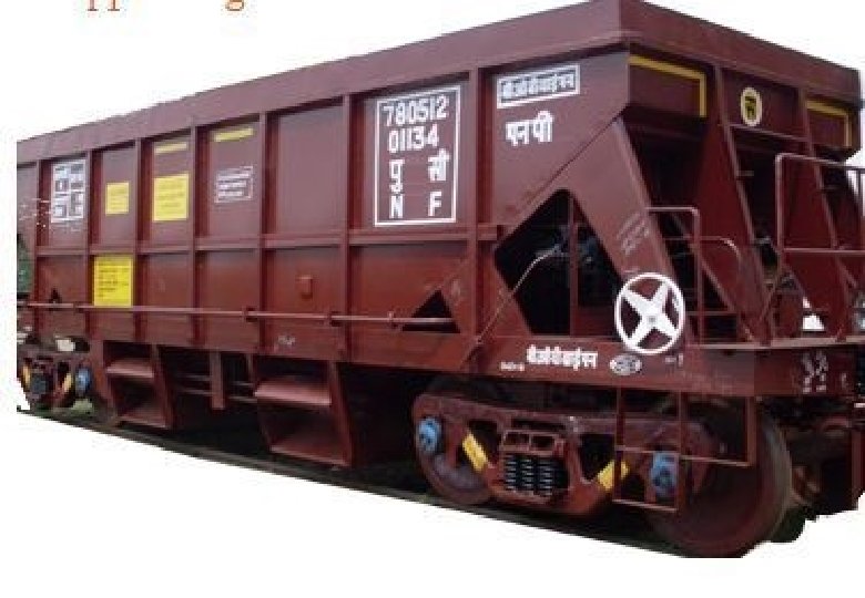
DETAILED SPECIFICATIONS WAGON MEASUREMENT l A continuous white line should be painted inside the wagon l The cubical content in cubic meter corresponding to white line should also be painted on both sides outside the wagon. l In addition, short pieces of flats with cubical contents punched shall be welded at the centre of all the four sides as permanent reference. l In case the supply is taken in general service wagons, actual measurements will be taken. 34
35
DETAILED SPECIFICATIONS SHRINKAGE ALLOWANCE l Payment shall be made for the gross measurements either in stacks or in wagons without any deduction for shrinkage/voids. l When ballast supply is taken in wagons, shrinkage upto 8% shall be permitted at destination while verifying the booked quantities by the consignee. 36
SAMPLING AND TESTING l CL-5. 1. 1 The samples shall be drawn with due diligence and adequate precaution so that they represent the true nature and condition of the ballast. l 5. 1. 2 Being a heterogeneous material, the gradation of ballast loaded in wagons and/or dumped/inserted in the track may not remain same as that initially checked in stacks. Similarly in case of direct loading into wagons, the gradation at destination may not remain same as that at source, Therefore, the samples from wagons and track are not representative samples as far as gradation is concerned. Even in the same stack, results of two checks may not be same. l 5. 1. 3 The samples from a stack taken after lapse of a long period of stacking are not representative samples of the ballast initially supplied in the stack, due to settling down of smaller size particles in voids underneath, dirt/dust getting accumulated in the stack, rains etc.
SAMPLING AND TESTING l 5. 2 Sampling Frequency l In order to ensure supply of uniform quality of ballast, the following norms shall be followed in respect of sampling, testing and acceptance: l 5. 2. 1 On supply of the first 100 cum, the tests for Size & Gradation, Abrasion Value, Impact Value and Water Absorption (if prescribed) shall be carried out by Railway. Further supply shall be accepted only after this ballast satisfies the specifications for these tests. Railway reserves the right to terminate the contract as per GCC at this stage itself in case the ballast supply fails to conform with any of these specifications.
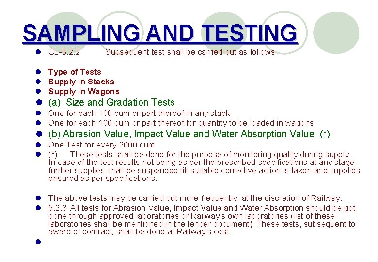
SAMPLING AND TESTING l l l l CL-5. 2. 2 Subsequent test shall be carried out as follows: Type of Tests Supply in Stacks Supply in Wagons l (a) Size and Gradation Tests l One for each 100 cum or part thereof in any stack l One for each 100 cum or part thereof for quantity to be loaded in wagons l (b) Abrasion Value, Impact Value and Water Absorption Value (*) l One Test for every 2000 cum l (*) These tests shall be done for the purpose of monitoring quality during supply. In case of the test results not being as per the prescribed specifications at any stage, further supplies shall be suspended till suitable corrective action is taken and supplies ensured as per specifications. l The above tests may be carried out more frequently, at the discretion of Railway. l 5. 2. 3 All tests for Abrasion Value, Impact Value and Water Absorption should be got done through approved laboratories or Railway’s own laboratories (list of these laboratories shall be mentioned in the tender document). These tests, subsequent to award of contract, shall be done at Railway’s cost. l
CL-5. 3 Supply of ballast in Stacks CL-5. 3. 1 Sampling Procedure l (i) Stack shall be kept in such a way that every part of the stack is accessible to the JCB or Power Equipment l (ii) Ballast supply in stacks: Three “Samples” each of 0. 3 -0. 5 cum one sample each from two sides and one sample from top after removing outer layer (150 -200 mm) should be collected for every 100 cum or part thereof, by JCB/suitable Power Equipment.
5. 3 Supply of ballast in Stacks (iii) The location (in plan) and depths of sampling points shall be varied for different “Samples” and different stacks in a lot. (iv)“Gross Sample” should be prepared by thoroughly mixing the three “Samples” l Note: For specific constraints, approval of Competent Authority (Engineer-in-charge) shall be taken prior to invitation of tender, for using manual means for collection and mixing of “Samples”, and this should be incorporated in the Tender Document.
5. 3 Supply of ballast in Stacks l (v) A “Test Sample” of volume 0. 027 cum shall be taken l (vi) Method for drawing “Test Sample”: The ballast in “Gross Sample” shall be scooped into a cone shaped pile by taking care to drop each scoopful exactly over the same spot. l After the cone is formed, it shall be flattened by pressing the top of cone with a smooth surface. Then it is cut into quarters by two lines which intersect at right angles at the centre of the cone.
5. 3 Supply of ballast in Stacks l The bulk of the sample is reduced by rejecting any two diagonally opposite quarters. The remaining ballast shall be mixed and “test sample” shall be drawn for testing. After drawing“ test sample”, the left over ballast of “Gross Sample” shall be dumped back in the stack. l (vii)Use tarpaulin or any other suitable sheet may be used on a flat surface for mixing, drawing and sieve analysis of samples. 43
5. 3 Supply of ballast in Stacks l 5. 3. 2 In case of stacks of volume more than 100 cum, more than one “Test Samples” will be tested for Gradation. l The full payment/reduced payment for the whole stack, as given in Para 2. 3 of the “Specifications for Track Ballast (IRS-GE-1, June-2004), shall be decided based on the average of the sieve analysis results of all the “Test Samples” for a stack.
Sampling of ballast in Heaps for loading directly in Wagons l Samples of ballast shall be collected from heaps of ballast proposed to be loaded into the wagons. l ADEN in-charge shall decide the location of heaps from which sampling is to be done, judiciously covering the entire quantity of ballast to be loaded in the rake. l Based on the approx. quantity of ballast to be loaded in the rake, methodology for sampling of ballast to be followed shall be the same as in Para-5. 3. 1 and 5. 3. 2 above.
Sampling Procedure • Sufficient space around the stack to facilitated movement of JCB/other ballast handling equipment. • Total 3 samples each of 0. 3 -0. 5 Cu. M for each 100 Cu. M or part thereof. (sample collection by JCB / other ballast handling equipment. ) • One sample from top (after removing outer layer of 150 -200 mm) & • Two samples one each from sides 46
• Location (in plan) & depth of sampling shall be varied for different samples & different stacks. • Gross sample is prepared by thoroughly mixing the three samples collected as above, using JCB. • Test sample of 0. 027 Cu. M is drawn from each gross sample for carrying out size and gradation analysis. 47
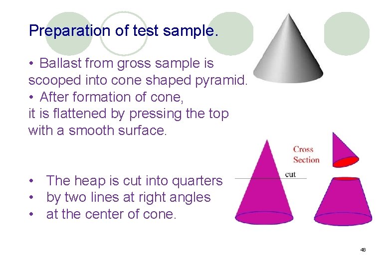
Preparation of test sample. • Ballast from gross sample is scooped into cone shaped pyramid. • After formation of cone, it is flattened by pressing the top with a smooth surface. • The heap is cut into quarters • by two lines at right angles • at the center of cone. 48
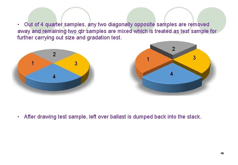
• Out of 4 quarter samples, any two diagonally opposite samples are removed away and remaining two qtr samples are mixed which is treated as test sample for further carrying out size and gradation test. 2 2 1 3 4 3 1 4 • After drawing test sample, left over ballast is dumped back into the stack. 49
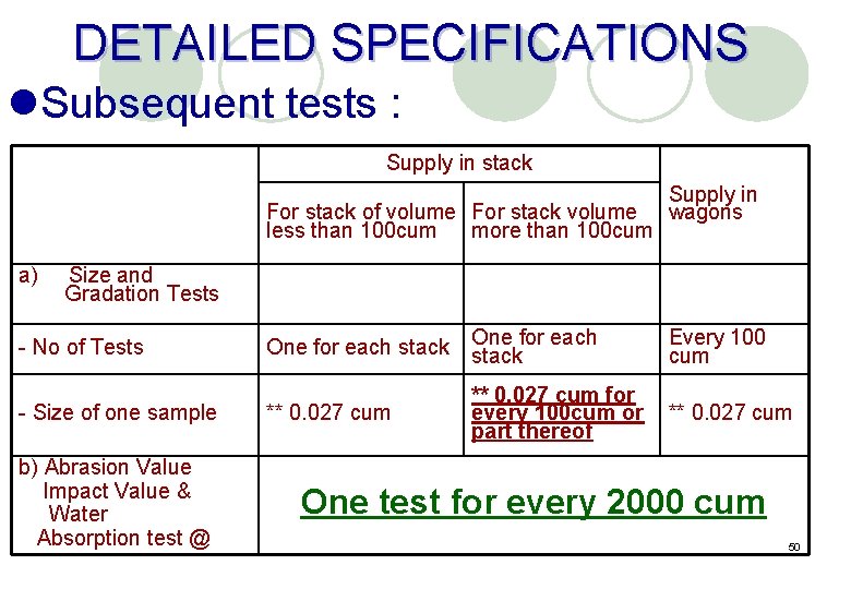
DETAILED SPECIFICATIONS l. Subsequent tests : Supply in stack For stack of volume For stack volume less than 100 cum more than 100 cum Supply in wagons a) Size and Gradation Tests - No of Tests - Size of one sample b) Abrasion Value Impact Value & Water Absorption test @ One for each stack ** 0. 027 cum Every 100 cum ** 0. 027 cum for every 100 cum or ** 0. 027 cum part thereof One test for every 2000 cum 50
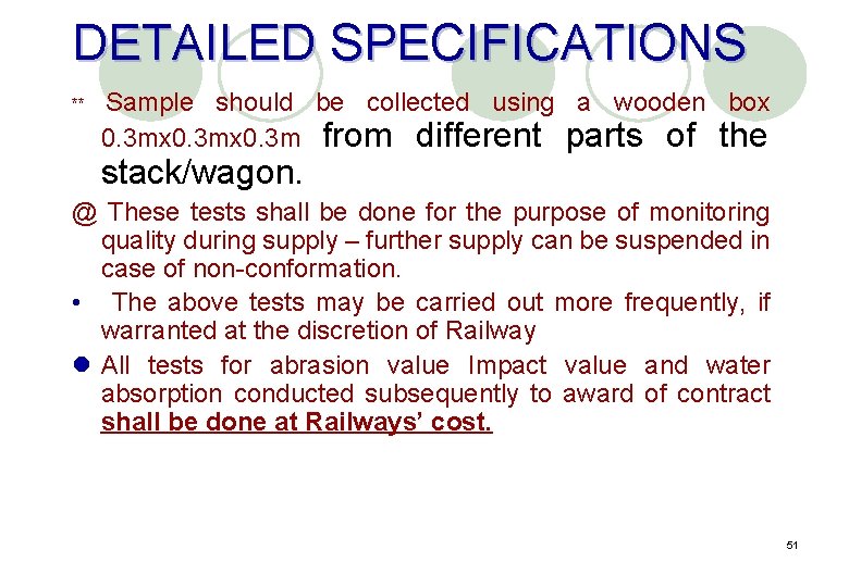
DETAILED SPECIFICATIONS ** Sample should be collected using a wooden box 0. 3 mx 0. 3 m from different parts of the stack/wagon. @ These tests shall be done for the purpose of monitoring quality during supply – further supply can be suspended in case of non-conformation. • The above tests may be carried out more frequently, if warranted at the discretion of Railway l All tests for abrasion value Impact value and water absorption conducted subsequently to award of contract shall be done at Railways’ cost. 51
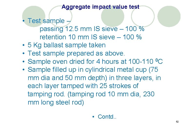
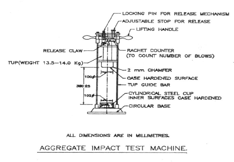
Aggregate impact value test • Test sample – passing 12. 5 mm IS sieve – 100 % retention 10 mm IS sieve – 100 % • 5 Kg ballast sample taken • Test sample prepared as above. • Sample oven dried for 4 hours at 100 -110 0 C • Sample filled up in cylindrical metal cup (75 mm dia and 50 mm depth) in three layers, in each layer tamped with 25 strokes of tamping rod. (tamping rod 10 mm dia, 230 mm long steel rod) • Contd. . 52
• Test sample filled up in steel cup is given 15 blows of 380 mm head (13. 5 to 14 Kg) • Each blow delivered at an interval not less than 1 sec. • Sample is then sieved through 2. 36 mm sieve and fraction passing (in %) through is calculated which is aggregate impact value. • Two such tests are carried out and mean of the two results (rounded to nearest whole number) is final aggregate impact value. 53
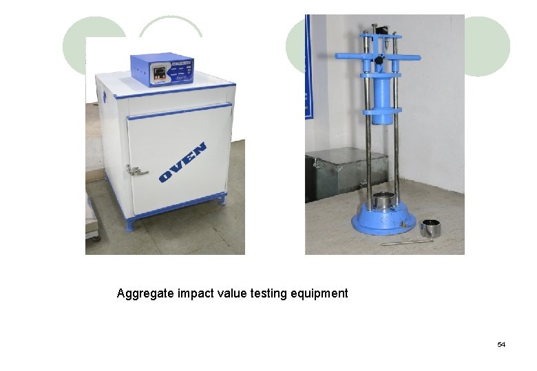
Aggregate impact value testing equipment 54
55
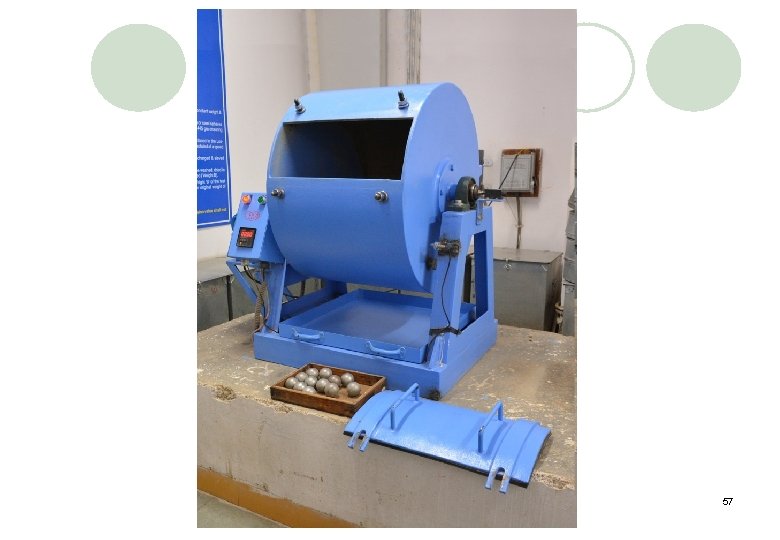
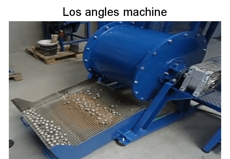
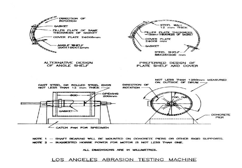
Aggregate abrasion value • Also called loss angels abrasion value • Test sample 10 Kg – passing 50 mm and retained on 40 mm sieve- 5 kg passing 40 mm and retained on 25 mm sieve- 5 kg (tolerance +/- 2%) • Dried in oven at 100 -110 o. C to constant weight • Abrasive charge 12 nos of CI/Steel balls dia – 48 mm (approx. ) is weighing 390 – 445 gm total weight 5 Kg +/- 25 gm. • Total 1000 revolution @ 20 -33 revolution per minute. • Sample received is sieved through 1. 7 mm IS sieve. • Material retained on 1. 7 mm sieve is washed and dried to constant weight. • Loss in weight in % is called aggregate abrasion value. 56
57
Los angles machine
59
Water absorption test • Ballast sample- 2 kg. • Sample thoroughly washed, placed in wired basket and immersed in distilled water at temp 2232 0 C. • Basket is lifted and dropped 25 times in 25 sec and then kept immersed in water for 24 +/- ½ hour. • Basket removed from water and allowed to drain for few minutes. • Aggregates are taken out and kept on dry cloth and is surface dried. 60
• Sample is kept in shed (away from direct sunlight). • Sample is now SSD (Saturated and surface dried). • SSD sample is weighed. (A) • Sample is now placed in oven for 24 hours at 100 -110 0 C & weight of sample is taken. (B) • water absorption = {(A-B)/B} X 100 • Two such tests shall be made and mean values is taken as water absorption %. 61
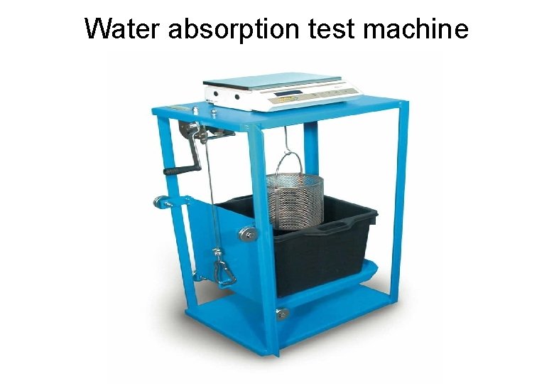
Water absorption test machine
Collection and Training out of Ballast– l The collection of ballast can either be done- l By resorting to alongside collection, or l By collecting at depots and training them out in ballast trains. l The mode of collection will have to be decided taking into account proximity of quarry, availability of good stone ballast, service roads alongside the line for carrying of ballast, availability of ballast trains, the turn round of ballast trains and availability of block for unloading. 63
Along side collection (Cess collection) IRPWM Para no 214 (1) • SSE/P. Way in-charge of section shall maintain a register showing the measurements of stacks and their deposition (KM TO KM ). • Stacks should be serially numbered between posts. • Entry shall be made in register whenever the ballast is removed and put in track. • Record should show the place where removed ballast used with date of removal.
Measurement of ballast IRPWM Para no 103 • In open line ADEN can measure and record the measurements by himself. • If ballast measurements are recorded by SSE/JE P. Way ADEN has to carry out 100% test check for both quality and quantity. • In construction AXEN will measure and record measurements by himself.
Depot collection of ballast • SSE/P. Way in-charge of depot shall maintain a register showing all transactions. • Space along railway siding shall be divided into convenient number of zones and demarcated. • For each depot a depot diagram shall be maintained with site details of stacks. • Each stack in each zone shall be serially numbered.
Depot collection of ballast • Operations of collection and training out of materials shall not be carried out at the same time in same zone. • The ground on which stacks are made to be selected and levelled. • No stack shall be less than one metre in height. • Measurements should be for complete stacks. • Measured stacks to be identified by sprinkling lime or any other method.
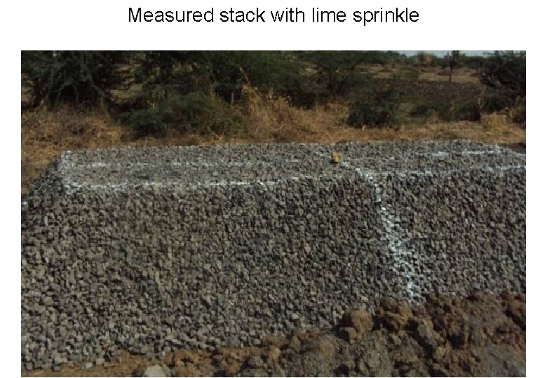
Measured stack with lime sprinkle
Unloading Ballast along the Line l IRPWM Para 216 l When unloading ballast along the line care shall be taken that the heaps at the sides and the centre are clear of prescribed running dimensions. Care should be taken to ensure that Ballast shall be cleared from the signal wires or point rods and no stone is left inadvertently between the stock rail and tongue rail. 69
Operation of Hoppers – l The hopper valves shall be operated according to the prescribed instructions under the direct supervision of the train guard or official-in-charge. As far as possible one hopper may be unloaded at a time moving at walking speed. The official-in-charge should walk on the side and instruct the labour as to when to open or close the hopper valves. The train should not be stopped, while ballast is being discharged; labour should not be moved from the platform without first stopping the train. 70
Surplus Ballast Along the Line l IRPWM Para 216 l All surplus ballast left alongside the line should be collected and stacked in regular heaps and not left scattered on the slopes to be overgrown by grass and lost. 71
PRECAUTIONS WHILE UNLOADING/SPREADING OF BALLAST l DOs l 1) Unloading of ballast shall be done under the supervision of a responsible P. Way supervisor not below the rank of a P. Way Supervisor. l 2) Ensure that the safety equipments and first aid boxes are available with supervisor and gangs AND are in good working order and in updated condition.
l Ensure that Contractor’s Supervisor/Workmen are counselled about safety measures. A competency certificate to the contractor’s supervisor is to be issued by the AEN. l When unloading ballast along the track, care shall be taken that the heaps at the sides and the centre of track are cleared off the prescribed moving dimensions. There should not be a possibility of ballast rolling down due to vibration & infringing the running rails. l Ensure protection of ballast train as per GR 15. 09 and IRPWM Para 806(I). l Before entering into block section, opening of doors should be checked and if all of the doors of any BOBY are not opening properly, unloading should not be done from that wagon and C&W staff should be booked on the next day.
l While the ballast train is working it should be ensured that all the doors are opened and the ballast is spread uniformly. On curves, inner side door should be adjusted so that the required quantity of unloading is ensured on both the sides. l While unloading ballast from hoppers, care to be taken in point and Xing zones, so that check rails are cleared and also gap between tongue rail and stock rail is clear. PWI in charge of work shall ensure above aspects before leaving the site of work. l While unloading ballast from N-BOX in electrified territory, the site of unloading shall be verified in advance for implantation of at least 2. 50 m. At locations where implantation is less than 2. 5 m, unloading shall not be done as the door may hit the electrical mast causing unsafe situation.
l SEJs should be cleared off stone ballast after unloading. l Ensure proper brake power of the train, before entering the block section. l Ensure closure of side door of BCN wagon after unloading of ballast in section to avoid infringement. l Ensure clearance of ballast properly to avoid jamming of signal rods, gears, lock bars after unloading. l DON’Ts l Do not allow any safety category staff who are overdue for refresher course, to under take the work. l Don't take ballast train into section for unloading if any hopper is having uneven load. In ghat sections having sharp curvature, preferably BOBY’N’ should be used for even distribution of ballast on either side of rail.
Safety measures/precautions to be taken after completion of work and before leaving the site l DOs l Ensure that unloaded ballast from ballast train and manually spread ballast in case of cess supply should be kept clear off moving dimensions. l Ballast shall not be unloaded over signal wires or point rods. Care should be taken to ensure that no stone is left inadvertently between the stock rail, tongue rail, check rail & nose of crossings. l Ballast which has fallen between the running rail and check rail on curves or LCs should be cleared invariably before cancellation of block.
l DONT’s l Don’t leave site unless ballast heaps if any formed during unloading is properly profiled to clear the moving dimensions. l Ballast shall not be unloaded on LC road surface, blocking road traffic & gate operating wire. l Bond wire should be kept clear off ballast. These should not be embedded in ballast. l OHE Mast should be clear off ballast so that it can be checked whether bonding of mast with rail is intact or not. l Excess ballast should not be unloaded in rear of ballast wall in approaches of girder bridges to avoid ballast from rolling on to the riverbed. l If the ballast train has stopped during unloading, after unloading of ballast from ballast train, it should be ensured that the ballast is clear off the top table of the rail and flange way before movement of the train.
- Slides: 77