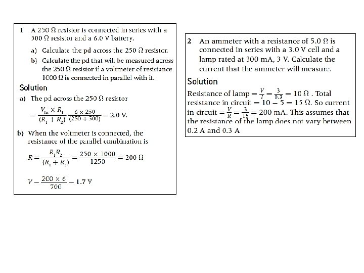
5 1 Electric fields Charge the conservation of


 Left")
 Up")
 Up")


 PRACTICE: An electron is moved from")


 What is")


 has R = 25 in bright")


 EXAMPLE: How much chemical energy is converted to electrical")


 How do you know that the charge will be in uniform circular motion?")


 b)")


- Slides: 88
5. 1 Electric fields
Charge – the conservation of charge PRACTICE: A cat’s fur acts like your hair, when you rub a balloon on it. A balloon has picked up -150 C of charge from Albert. The resulting opposite charges of balloon and Albert cause the balloon to stick. (a) How many electrons have been transferred? (b) What is the charge on Albert? SOLUTION: 1 e- = -1. 60 10 -19 C so… (a) n = (-150 10 -6 C)/ (-1. 60 10 -19 C) = 9. 4 1014 e-. (b) Conservation of charge tells us that q. Albert = +150 C. PRACTICE: Many houses have 20 -amp(ere) service. How many electrons per second is this? SOLUTION: ▪ 20 A is 20 C (per s) so we only need to know how many electrons are in 20 C. (20 C)(1 e- / 1. 6 10 -19 C) = 1. 3 1020 e-.
EXAMPLE - QUESTION Charging by induction Bring a charged object near a conducting surface, electrons will move in conductor even though no physical contact: Due to attraction or repulsion of electrons in conductor to the charged object – since free to move, they will! Once separated from each other with rod still close they’ll remain charged. Charge is conserved, so charges on spheres A and B are equal and opposite. Note, the charged rod never touched them, and retains its original charge.
Charge – detection using an electroscope PRACTICE: Consider the three electroscopes shown. Which one has the greatest charge in the leaves? Which one has the least? Can you tell whether the charge is (+) or (-)? Why? SOLUTION: ▪ The last one has the most charge, the middle one the least. ▪ You cannot tell the sign of the charge since (-)(-) will repel, but so will (+)(+).
Charge – detection using an electroscope during before and after PRACTICE: Explain: A charged wand is brought near an uncharged electroscope without touching it. While the wand is near, the leaves spread apart. SOLUTION: ▪ The ball and the leaves are conductors and they are connected to each other. ▪ The wand’s charge repels like charges in the ball. ▪ The like charges in the ball travel as far as they can to the leaves. ▪ The leaves now temporarily hold like charges and thus they repel each other.
Practice: Coulomb’s law Find the Coulomb force between two electrons located 1. 0 cm apart. SOLUTION: ▪ Note r = 1. 0 cm = 0. 010 m. ▪ Note q 1 = e = 1. 60 10 -19 C. ▪ Note q 2 = e = 1. 60 10 -19 C. ▪ From F = kq 1 q 2 / r 2 F = 8. 99 109 (1. 60 10 -19)2 / 0. 0102 = 2. 30 10 -24 N. ▪ Since like charges repel the electrons repel. PRACTICE: Find the electric field strength 1. 0 cm from an electron. SOLUTION: We have already found the Coulomb force between two electrons located 1. 0 cm apart. We just divide our previous answer by one of the charges: ▪ Then E = F / q = 2. 3 10 -24 / 1. 6 10 -19 = 1. 4 10 -5 N C-1.
SHE accumulates a charge q 1 of 2. 0 x 10 -5 C (sliding out of the seat of a car). HE has accumulated a charge q 2 of – 8. 0 x 10 -5 C while waiting in the wind. What is the force between them a) when she opens the door 6. 0 m from him and b) when their separation is reduced by a factor of 0. 5? a) They exert equal forces on each other only in opposite direction (“-“ = attractive force) b) r’ = 0. 5 r Strong force at very small separation spark How many electrons is 2. 0 x 10 -5 C ?
Three point charges : q 1= +8. 00 m. C; q 2= -5. 00 m. C and q 3= +5. 00 m. C. (a) Determine the net force (magnitude and direction) exerted on q 1 by the other two charges. (b) If q 1 had a mass of 1. 50 g and it were free to move, what would be its acceleration? 1. 30 m 230 q 1 q 2 230 1. 30 m Force diagram F 3 q 3 q 1 F 2 electric force is very-very strong force, and resulting acceleration can be huge
A positive and negative charge with equal magnitude are connected by a rigid rod, and placed near a large negative charge. In which direction is the net force on the two connected charges? 1) Left 2) Zero 3) Right Positive charge is attracted (force to left) Negative charge is repelled (force to right) Positive charge is closer so force to left is larger. - + -
Coulomb’s law – permittivity – practice If the two electrons are embedded in a chunk of quartz, having a permittivity of 12 0, what will the Coulomb force be between them if they are 1. 0 cm apart? SOLUTION: F = (1/[4 ])q 1 q 2 / r 2 = (1/[4 12 8. 85 10 -12]) (1. 60 10 -19)2 / 0. 0102 = 1. 92 10 -25 N.
Coulomb’s law – extended distribution ▪ Coulomb’s law works not only for point charges, which have no radii, but for any spherical distribution of charge at any radius. ▪ Be very clear that r is the distance between the centers of the charges. Q q r EXAMPLE: A conducting sphere of radius 0. 10 m holds an electric charge of Q = +125 C. A charge q = -5. 0 C is located 0. 30 m from the surface of Q. Find the electric force between the two charges. · r = 0. 10 + 0. 30 = 0. 40 m · F= k. Qq / r 2 = 8. 99 109 25 10 -6 5. 0 10 -6 / 0. 40 2 = 35 N, toward positive charge
Question Say the electric field from an isolated point charge has a certain value at a distance of 1 m. How will the electric field strength compare at a distance of 2 m from the charge? It will be ¼ as much – inverse square law force between two charges carries over to the electric field from a point charge.
Solving problems involving electric fields EXAMPLE: Suppose test charges are placed at points A and B in the electric field of the dipole, as shown. Trace their paths when released. SOLUTION: ▪ Just remember: Test charges travel C with the field arrows and on the field lines. A PRACTICE: Suppose small negative charges are placed at points C and D in the electric field of the dipole, as shown. Trace their paths when released. SOLUTION: ▪ Just remember: (-) charges travel against the field arrows and on the field lines. B D
Electric field – sketching PRACTICE: We can simplify our drawings of electric fields by using top views and using rays. Which field is that of the… (a) Largest negative charge? D (b) Largest positive charge? A (c) Smallest negative charge? C (d) Smallest positive charge? E SOLUTION: The larger the charge, the more concentrated the field. ▪ Lines show the direction a positive test charge will go. ▪ Outward is (+) charge, inward (-). A B D C E F
Question? What is the direction of the electric field at point C? 1) Left 2) Right 3) Zero Away from positive charge (right) Towards negative charge (right) y Net E field is to right. C x
Question? What is the direction of the electric field at point A? 1) Up 2) Down 3) Left 4) Right 5) Zero A x
Question? What is the direction of the electric field at point B? 1) Up 2) Down 3) Left 4) Right 5) Zero y B x
Question? What is the direction of the electric field at point A, if the two positive charges have equal magnitude? 1) Up 2) Down 3) Left 4) Right 5) Zero A x
Solving problems involving electric fields EXAMPLE: Two charges of -0. 225 C each are located at opposite corners of a square having a side length of 645 m. Find the electric field vector at E 2 q 1 (a) the center of the square, and (b) one of the unoccupied corners. s E 1 (a) SOLUTION: Start by making a sketch. E 2 = (8. 99 109)(0. 225) / 645 2 = 4860 NC-1 2 E ( ). E 2 = E 12 + E 22 = 2(4860)2 = 47239200 E = 6870 NC-1. 1+ ( ). = (8. 99 109)(0. 225) / 645 2 = 4860 NC-1 E E 1 q 2 s (a)The opposing fields cancel so E = 0. (b) The two fields are at right angles. (b) E 1 E 2 sum points to center of square
Solving problems involving electric fields PRACTICE: Two stationary charges are shown. At which point is the electric field strength the greatest? SOLUTION: ▪ Sketch in the field due to each charge at each point. ▪ Fields diminish as 1 / r 2. ▪ Fields point away from (+) and toward (-). ▪ The only place the fields add is point B.
Coulomb’s law – extended distribution ▪ Coulomb’s law works not only for point charges, which have no radii, but for any spherical distribution of charge at any radius. ▪ Be very clear that r is the distance between the centers of the charges. Q q r EXAMPLE: A conducting sphere of radius 0. 10 m holds an electric charge of Q = +125 C. A charge q = -5. 0 C is located 0. 30 m from the surface of Q. Find the electric force between the two charges. · r = 0. 10 + 0. 30 = 0. 40 m · F= k. Qq / r 2 = 8. 99 109 25 10 -6 5. 0 10 -6 / 0. 40 2 = 35 N, toward positive charge
Solving problems involving electric fields PRACTICE: An isolated metal sphere of radius 1. 5 cm has a charge of -15 n. C placed on it. (a) Sketch in the electric field lines outside the sphere. (b) Find the electric field strength at the surface of the sphere. (c) An electron is placed on the outside surface of the sphere and released. What is its initial acceleration? SOLUTION: (a) Field lines point towards (-) charge. (b) The field equation works as if all of the charge is (-) at the center of the spherical distribution. E = k. Q / r 2 (c) The electron feels force F = Eq so that = (8. 99 109)(15 10 -9) / 0. 0152 = 6. 0× 105 NC-1. F = Ee = (6. 0 105)(1. 6 10 -19) = 9. 6 10 -14 N. a = F / m = (9. 6 10 -14) / (9. 11 10 -31) = 1. 1 1017 m s-2.
Solving problems involving electric fields PRACTICE: If the charge on a 25 cm radius metal sphere is +150 C, calculate (a) the electric field strength at the surface. (b) the field strength 25 cm from the surface. (c) the force on a -0. 75 C charge placed 25 cm from the surface. SOLUTION: Use E = k. Q / r 2, and for (c) use E = F / q. (a) E = k. Q / r 2 = (8. 99 109)(150 10 -6) / 0. 25 2 = 2. 2 107 NC-1. (b) E = (8. 99 109)(150 10 -6) / 0. 50 2 = 5. 4 106 NC-1. (c) F = Eq = (5. 4 106)(-0. 75 10 -6) = -4. 0 N. The minus sign means it is an attractive force.
PRACTICE: The uniform electric field strength inside the parallel plates is 275 N C-1. A +12 C charge having a mass of 0. 25 grams is placed in the field at A and released. (a) What is the electric force acting on the charge? (b) What is the weight of the charge? SOLUTION: (a) F = Eq = (275)(12 10 -6) = 0. 0033 N. E (b) F = mg = (0. 00025)(9. 8) = 0. 0025 N. A (c) What is the acceleration of the charge? SOLUTION: Use Fnet = ma. The electric force is trying to make the charge go up, and the weight is trying to make it go down. Thus Fnet = 0. 0033 - 0. 0025 = 0. 0008 N. Fnet = ma 0. 0008 = 0. 00025 a a = 3. 2 m s-2 ( ). 0. 025 m Electric field – between parallel plates
Potential difference PRACTICE: A charge of q = +15. 0 C is moved from point A, having a voltage (potential) of 25. 0 V to point B, having a voltage (potential) of 18. 0 V. (a) What is the potential difference undergone by the charge? (b) What is the work done in moving the charge from A to B? SOLUTION: A B q (a) V = VB – VA = 18. 0 – 25. 0 = – 7. 0 V. (b) W = q. V = 15. 0 10 -6 -7. 0 = – 1. 1 10 -4 J. ▪ Many books use V instead of V.
Potential difference – the electronvolt (1 e. V) PRACTICE: An electron is moved from Point A, having a voltage (potential) of 25. 0 V, to Point B, having a voltage (potential) of 18. 0 V. (a) What is the work done (in e. V and in J) on the electron A by the external force during the displacement? q ▪ W = q(VB – VA). ▪ W = -e(18. 0 V – 25. 0 V) = 7. 0 e. V. ▪ W = 1. 60 10 -19 C (18. 0 V – 25. 0 V) = 1. 12 10 -18 J B 1 e. V = 1. 60 10 -19 J (b) If the electron is released from Point B, what is its speed when it reaches Point A? A Work is now stored as potential energy. U=1. 12 10 -18 J EK = U (1/2)mv 2 – (1/2)mu 2 = 1. 12 10 -18 (1/2)(9. 11 10 -31)v 2 = 1. 12 10 -18 v = 1. 57 106 ms-1. q B
Potential difference – path independence EXAMPLE: A charge of q = +15. 0 C is moved from point A, having a voltage (potential) of 25. 0 V to point B, having a voltage (potential) of 18. 0 V, in three different ways. What is the work done in each case? SOLUTION: A B ▪ The work is independent of the path because the electric force is a conservative force. ▪ W = q. V = 15. 0 10 -6 (-7. 0) = -1. 1 10 -4 J. Same for all. ▪ Gravitational force is also a conservative force. You remember that work done by gravitational force will be the same (converted into KE) if we throw a stone from certain height with the same speed in any direction.
Potential difference – between parallel plates PRACTICE: Two parallel plates with plate separation d are charged up to a potential difference of V simply by connecting a battery (shown) to them. The electric field between the plates is E. A positive charge q is moved from A to B. (a) How much work is done in moving q through the distance d? (b) Find the potential difference V across the plates. W = Fd cos , F = Eq, and W = q. V. (a) W = Fd cos 0° = (Eq)d. (b) q. V = Eqd V = Ed. A d E B
Potential difference – between parallel plates PRACTICE: Two parallel plates with plate separation 2. 0 cm are charged up to the potential difference shown. Which one of the following shows the correct direction and strength of the resulting electric field? ▪ Since the greater positive is plate Y, the electric field lines point from Y X. ▪ From V = Ed we see that E =V/d = (100 – 50) / 2 = 25 V cm-1.
Drift speed I = n. Avq current vs. drift velocity PRACTICE: Suppose the current in a 2. 5 mm diameter copper wire is 1. 5 A and the number density of the free electrons is 5. 0 1026 m-3. Find the drift velocity. I = n. Avq, where A = d 2/ 4 = (2. 5 10 -3) 2/ 4 = 4. 91 10 -6 m 2. v = I / [n. Aq] = 1. 5 / [5. 0 1026 4. 91 10 -6 1. 6 10 -19 ] = 0. 0038 ms-1.
Drift speed PRACTICE: Suppose the drift velocity is 0. 0025 ms-1 for your house wiring. If the wire between your light switch and your light bulb is 6. 5 meters, how long does it take an electron to travel from the switch to the bulb? t = d / v = 6. 5 / 0. 0025 = 2600 s = 43. 33 min! PRACTICE: Why does the bulb turn on instantly? all of the free electrons begin moving at the same time through the whole circuit.
Resistance ▪ Note that resistance depends on temperature. The IBO does not require us to explore this facet of resistivity. PRACTICE: What is the resistance of a 0. 00200 meter long carbon core resistor having a core diameter of 0. 000100 m? Assume the temperature is 20 C. ▪ r = d / 2 = 0. 0001 / 2 = 0. 00005 m. ▪ A = r 2 = (0. 00005)2 = 7. 854 10 -9 m 2. ▪ From the table = 3600 10 -8 m. R = L / A = (3600 10 -8)(0. 002) / 7. 854 10 -9 = 9. 17 . A L
Examples • If a 3 volt flashlight bulb has a resistance of 9 ohms, how much current will it draw? • I = V / R = 3 V / 9 = 0. 33 A • If a light bulb draws 2 A of current when connected to a 120 volt circuit, what is the resistance of the light bulb? • R = V / I = 120 V / 2 A = 60
Example A copper wire has a length of 1. 60 m and a diameter of 1. 00 mm. If the wire is connected to a 1. 5 -volt battery, how much current flows through the wire? The current can be found from Ohm's Law, V = IR. The V is the battery voltage, so if R can be determined then the current can be calculated. The first step, then, is to find the resistance of the wire: L = 1. 60 m. r = 0. 5 mm = 1. 72 x 10 -8 m, copper - books The resistance of the wire is then: R = L/A = (1. 72 x 10 -8 m)(1. 60)/(7. 9 x 10 -7 m 2 ) = 3. 50 The current can now be found from Ohm's Law: I = V / R = 1. 5 / 3. 5 = 0. 428 A
Ohmic and Non-Ohmic behaviour EXAMPLE: The graph shows the applied voltage V vs resulting current I through a tungsten filament lamp. a. Find R when I = 0. 5 m. A and 1. 5 m. A. Is this filament ohmic or non-ohmic? ▪ At 0. 5 m. A: V = 0. 08 V R = V / I = 0. 08 / 0. 5 10 -3 = 160 . ▪ At 1. 5 m. A: V = 0. 6 V R = V / I = 0. 6 / 1. 5 10 -3 = 400 . b. Explain why a lamp filament might be non-ohmic. ▪ tungsten is a conductor. ▪ Therefore, the hotter the filament the higher R. ▪ But the more current, the hotter a lamp filament burns. ▪ Thus, the bigger the I the bigger the R. Since R is not constant the filament is non-ohmic.
Ohmic and Non-Ohmic behaviour EXAMPLE: The I-V characteristic is shown for a non-ohmic component. Sketch in the I-V characteristic for a 40 ohmic component in the range of 0. 0 V to 6. 0 V. ▪ ”Ohmic” means V = IR and R is constant (and the graph is linear). ▪ V = I 40 or I = V / 40. ▪ If V = 0, I = 0 / 40 = 0. 0. ▪ If V = 6, I = 6 / 40 = 0. 15 A = 150 m. A.
Power dissipation PRACTICE: The graph shows the V-I characteristics of a tungsten filament lamp. What is its power consumption at I = 0. 5 m. A and at I = 1. 5 m. A? ▪ At 0. 5 m. A, V = 0. 08 V. ▪ P = IV = (0. 5 10 -3)(0. 08) = 4. 0 10 -5 W. ▪ At 1. 5 m. A, V = 0. 6 V. ▪ P = IV = (1. 5 10 -3)(0. 6) = 9. 0 10 -4 W.
Resistors in Series EXAMPLE: Three resistors of 330 each are connected to a 6. 0 V battery in series R 1 (a) What is the circuit’s equivalent resistance? (b) What is the current in the circuit? (a) R = R 1 + R 2 + R 3 R = 330 + 330 = 990 . (b) I = V / R = 6 / 990 = 0. 0061 A. R 2 R 3 (c) What is the voltage on each resistor? (c) The current I we just found is the same everywhere. Thus each resistor has a current of I = 0. 0061 A. ▪ From Ohm’s law, each resistor has a voltage given by V = IR = (0. 0061)(330) = 2. 0 V. ▪ In series the V’s are different if the R’s are different.
Total resistance of resistors in series is greater than the greatest Total resistance of resistors in parallel is smaller than the smallest
RESISTORS IN COMPOUND CIRCUITS Now you can calculate current, potential drop and power dissipated through each resistor
resistors in parallel EXAMPLE: Three resistors of 330 each are connected to a 6. 0 V cell in parallel as shown. (a) What is the circuit’s resistance? R 2 R 1 (b) What is the voltage on each resistor? R 3 (a) In parallel, 1 / R = 1 / R 1 + 1 / R 2 + 1 / R 3 so that 1 / R = 1 / 330 + 1 / 330 = 0. 00909. Thus R = 1 / 0. 00909 = 110 . (b) The voltage on each resistor is 6. 0 V, since the resistors are in parallel. (Each resistor is clearly directly connected to the battery). (c) What is the current in each resistor? (c) Using Ohm’s law (I = V / R): I 1 = V 1 / R 1 = 6 / 330 = 0. 018 A. I 2 = V 2 / R 2 = 6 / 330 = 0. 018 A. I 3 = V 3 / R 3 = 6 / 330 = 0. 018 A. ▪ In parallel the I’s are different if the R’s are different.
5. 2 – Heating effect of electric currents Circuit diagrams - voltmeters are connected in parallel PRACTICE: Draw a schematic diagram circuit: SOLUTION: FYI ▪ Be sure to position the voltmeter across the desired resistor in parallel. for this 1. 06
ce pla ten EXAMPLE: A battery’s voltage is measured as shown. (a) What is the uncertainty in it’s measurement? SOLUTION: ▪ For digital devices always use the place value of the least significant digit as your raw uncertainty. ▪ For this voltmeter the voltage is measured to the tenths place so we give the raw uncertainty a value of ∆V = 0. 1 V. ths Circuit diagrams - voltmeters are connected in parallel 09. 4 00. 0 (b) What is the fractional error in this measurement? SOLUTION: Fractional error is just V / V. For this particular measurement : · V / V = 0. 1 / 9. 4 = 0. 011 (or 1. 1%). ▪ When using a voltmeter the red lead is placed at the point of highest potential.
Potential divider circuits PRACTICE: Find the output voltage if the battery has an emf of 9. 0 V, R 1 is a 2200 resistor, and R 2 is a 330 resistor. SOLUTION: ▪ VOUT = VIN [ R 2 / (R 1 + R 2) ] VOUT = 9 [ 330 / (2200 + 330) ] VOUT = 9 [ 330 / 2530 ] = 1. 2 V. PRACTICE: Find the value of R 2 if the battery has an emf of 9. 0 V, R 1 is a 2200 resistor, and we want an output voltage of 6 V. SOLUTION: ▪ VOUT = VIN [ R 2 / (R 1 + R 2) ] 6 = 9 [ R 2 / (2200 + R 2) ] 6(2200 + R 2) = 9 R 2 13200 = 3 R 2 = 4400 ▪ The bigger R 2 is in comparison to R 1, the closer VOUT is in proportion to the total voltage.
Potential divider circuits PRACTICE: A filament lamp is rated at “ 4. 0 V, 0. 80 W” on its package. The potentiometer has a resistance from X to Z of 24 and has linear variation. (a) Sketch the variation of the p. d. V vs. the current I for a typical filament lamp. Is it ohmic? ohmic means linear SOLUTION: Since the temperature increases with the current, so does the resistance. ▪ But from V = IR we see that R = V / I, which is the slope. ▪ Thus the slope should increase with I. R 1 R 2 (b) The potentiometer is adjusted so that the meter shows 4. 0 V. Will it’s contact be above Y, below Y, or exactly on Y? SOLUTION: The circuit is acting like a potential divider with R 1 being the resistance between X and Y and R 2 being the resistance between Y and Z. V non-ohmic ▪ Since we need VOUT = 4 V, and since VIN = 6 V, the contact must be adjusted above the Y. I
PRACTICE: A light sensor consists of a 6. 0 V battery, a 1800 Ω resistor and a light-dependent resistor in series. When the LDR is in darkness the pd across the resistor is 1. 2 V. (a) Calculate the resistance of the LDR when it is in darkness. (b) When the sensor is in the light, its resistance falls to 2400 Ω. Calculate the pd across the LDR. (a) As the pd across the resistor is 1. 2 V, the pd across the LDR must be 6 -1. 2=4. 8. The current in the circuit is The resistance of the LDR is (b) For the ratio of pds to be 1. 33, the pds must be 2. 6 V and 3. 4 V with the 3. 4 V across the LDR.
Potential divider circuits PRACTICE: A light-dependent resistor (LDR) has R = 25 in bright light and R = 22000 in low light. An electronic switch will turn on a light when its p. d. is above 7. 0 V. What should the value of R 1 be? SOLUTION: VOUT = VIN [ R 2 / (R 1 + R 2) ] 7 = 9 [ 22000 / (R 1 + 22000) ] 7(R 1 + 22000) = 9(22000) 7 R 1 + 154000 = 198000 R 1 = 6300 (6286)
Potential divider circuits PRACTICE: A thermistor has a resistance of 250 when it is in the heat of a fire and a resistance of 65000 when at room temperature. An electronic switch will turn on a sprinkler system when its p. d. is above 7. 0 V. (a) Should thermistor be R 1 or R 2? SOLUTION: ▪ Because we want a high voltage at a high temperature, and because thermistor’s resistance decreases with temperature, it should be placed at the R 1 position. (b) What should R 2 be? SOLUTION: In fire thermistor is R 1 = 250 . 7 = 9 [ R 2 / (250 + R 2) ] 7(250 + R 2) = 9 R 2 = 880 (875)
Potential divider circuits PRACTICE: A filament lamp is rated at “ 4. 0 V, 0. 80 W” on its package. The potentiometer has a resistance from X to Z of 24 and has linear variation. (a) Sketch the variation of the p. d. V vs. the current I for a typical filament lamp. Is it ohmic? ohmic means linear SOLUTION: Since the temperature increases with the current, so does the resistance. ▪ But from V = IR we see that R = V / I, which is the slope. ▪ Thus the slope should increase with I. R 1 R 2 (b) The potentiometer is adjusted so that the meter shows 4. 0 V. Will it’s contact be above Y, below Y, or exactly on Y? SOLUTION: The circuit is acting like a potential divider with R 1 being the resistance between X and Y and R 2 being the resistance between Y and Z. V non-ohmic ▪ Since we need VOUT = 4 V, and since VIN = 6 V, the contact must be adjusted above the Y. I
PRACTICE: A filament lamp is rated at “ 4. 0 V, 0. 80 W” on its package. The potentiometer has a resistance from X to Z of 24 and has linear variation. (c) The potentiometer is adjusted so that the meter shows 4. 0 V. What are the current and the resistance of the lamp at this instant? SOLUTION: P = 0. 80 W and V = 4. 0 V. ▪ P = IV 0. 8 = I(4) I = 0. 20 A. ▪ V = IR 4 = 0. 2 R R = 20. . ▪ You could also use P = I 2 R for this last one. (d) The potentiometer is adjusted so that the meter shows 4. 0 V. What is the resistance of the Y-Z portion of the potentiometer? SOLUTION: Let R 1 = X to Y and R 2 = Y to Z resistance. ▪ Then R 1 + R 2 = 24 so that R 1 = 24 – R 2. ▪ From VOUT = VIN [ R 2 / (R 1 + R 2) ] we get 4 = 7 [ R 2 / (24 – R 2 + R 2) ] R 2 = 14 (13. 71). R 1 R 2
PRACTICE: A filament lamp is rated at “ 4. 0 V, 0. 80 W” on its package. The potentiometer has a resistance from X to Z of 24 and has linear variation. (e) The potentiometer is adjusted so that the meter shows 4. 0 V. What is the current in the Y-Z portion of the potentiometer? SOLUTION: ▪ V 2 = 4. 0 V because it is in parallel with the lamp. I 2 = V 2 / R 2 = 4 / 13. 71 = 0. 29 A (f) The potentiometer is adjusted so that the meter shows 4. 0 V. What is the current in the ammeter? SOLUTION: The battery supplies two currents. ▪ The red current is 0. 29 A because it is the I 2 we just calculated in (e). ▪ The green current is 0. 20 A found in (c). ▪ The ammeter has both so I = 0. 29 + 0. 20 = 0. 49 A. R 1 R 2
Solving problems involving circuits PRACTICE: A battery is connected to a 25 -W lamp as shown. What is the lamp’s resistance? SOLUTION: Suppose we connect a voltmeter to the circuit. ▪ We know P = 25 W. ▪ We know V = 1. 4 V. ▪ From P = V 2 / R we get ▪ R = V 2/ P = 1. 4 2 / 25 = 0. 078 . 01. 4 00. 0
Solving problems involving circuits PRACTICE: Which circuit shows the correct setup to find the V-I characteristics of a filament lamp? ▪ The voltmeter must be in parallel with the lamp. ▪ It IS, in ALL cases. ▪ The ammeter must be in series with the lamp and must read only the lamp’s current. ▪ The correct response is B. two currents lamp current no currents short circuit!
Solving problems involving circuits PRACTICE: A non-ideal voltmeter is used to measure the p. d. of the 20 k resistor as shown. What will its reading be? SOLUTION: There are two currents in the circuit because the voltmeter does not have a high enough resistance to prevent the green one from flowing. ▪ The 20 k resistor is in parallel with the 20 k : 1 / R = 1 / 20000 + 1 / 20000 = 2 / 20000. R = 20000 / 2 = 10 k. ▪ But then we have two 10 k resistors in series and each takes half the battery voltage, or 3 V. equivalent ckt
Solving problems involving circuits PRACTICE: All three circuits use the same resistors and the same cells. Highest I 0. 5 R parallel Lowest I 2 R series Middle I 1. 5 R R 0. 5 R combo Which one of the following shows the correct ranking for the currents passing through the cells? SOLUTION: The bigger the R the smaller the I.
Solving problems involving circuits PRACTICE: The voltmeter has E infinite resistance. What are the readings on the voltmeter when the switch is open and closed? SOLUTION: ▪ With the switch open the green R is not part of the circuit. Red and orange split the battery emf. ▪ With the switch closed the red and green are in parallel and are (1/2)R.
Kirchhoff’s rules – solving the circuit EXAMPLE: Suppose each of the resistors is R = 2. 0 , and the emfs are 1 = 12 V and 2 = 6. 0 V. Find the voltages and the currents of the circuit. ▪ rule for I: I 1 – I 2 + I 3 = 0 (1) ▪ rule for V: –V 1 + –V 2 + –V 4 + 1 + – 2 = 0 (2) ▪ rule for V: – 2 – V 3 – V 4 = 0 (3) (2) – 2 I 1 + – 2 I 2 + 12 + – 6 = 0 (4) (3) –– 6 – 2 I 3 – 2 I 2 = 0 (5) We now have three equations in I: (1) I 3 = I 2 – I 1 = 1. 8 A (4) 3 = 2 I 1 + I 2 = -0. 6 A I 3 = -2. 4 A (5) 3 = -I 2 + -I 3 Since I 2 and I 3 are negative, we chose the wrong directions. V=IR
Finally, we can redraw our currents: I 1 = 1. 8 A I 2 = 0. 6 A I 3 = 2. 4 A resistor voltages: V = IR V 1 = 1. 8(2) = 3. 6 V. V 2 = 1. 8(2) = 3. 6 V. V 3 = 2. 4(2) = 4. 8 V. V 4 = 0. 6(2) = 1. 2 V
Cells – electric potential difference EXAMPLE: 200 C of charge is brought from an electric potential of 2. 0 V to an electric potential of 14 V through use of a car battery. What is the change in potential energy of the charge? ▪ ∆V = ∆ U/ q ▪ ∆U = q∆V. ∆U = q(V – V 0) ∆U = (200 10 -6)(14 – 2) ∆U = 0. 0024 J. FYI ▪ Note the increase rather than the decrease.
Cells – electromotive force (emf) EXAMPLE: How much chemical energy is converted to electrical energy by the cell if a charge of 15 C is drawn by the voltmeter? ∆V = U/ q. U = q = (1. 6)(15 10 -6) = 2. 4 10 -5 J. 01. 6
Cells – internal resistance PRACTICE: A battery has an internal resistance of r = 1. 25 . What is its rate of heat production if it is supplying an external circuit with a current of I = 2. 00 A? Rate at which electrical energy is converted into thermal is power. P = IV = I 2 r P = (2 2)(1. 25) = 5. 00 W FYI ▪ If you double the current, the rate of heat generation will quadruple because of the I 2 dependency. ▪ If you accidentally “short circuit” a battery, the battery may even heat up enough to leak or explode!
When a dry cell is connected to a circuit with a load resistor of 4. 0 Ω, there is a terminal voltage of 1. 3 V. When the load resistor is changed to 12 Ω, the terminal voltage is found to be 1. 45 V. Calculate (a) the emf of the cell. (b) the internal resistance of the cell.
Cells – internal resistance PROBLEM: A cell has an unloaded voltage of 1. 6 V and a loaded voltage of 1. 5 V when a 330 resistor is connected as shown. (a) Find . (b) Find I. (c) Find the cell’s internal resistance. (d) What is the terminal potential difference (t. b. d. ) of the cell? 1. 6 V (a) From the first schematic we see that = 1. 6 V. (Unloaded cell. ) (b) From the second diagram we see that the voltage across the 330 resistor is 1. 5 V. (Loaded cell. ) I = 1. 5/330=0. 0045 A. (c) = IR + Ir. 1. 6 = 1. 5 + 0. 0045 r r = 22 (d) The terminal potential difference is the potential difference at the terminals of the cell where it connects to the external circuit. ▪ This cell has an unloaded t. p. d (emf) of 1. 6 V, and a loaded t. p. d. of 1. 5 V. Note that the t. p. d. depends on the load. 1. 5 V V = IR
Solving problems involving magnetic fields PRACTICE: Find the magnetic flux density 1. 0 cm from a straight wire carrying a current of 25 A. SOLUTION: Magnetic flux density is just B. ▪ Use B = 0 I / (2 d) where d = 1. 0 cm = 0. 010 m. B = 4 10 -7 25 / [2 0. 010] = 5. 0 10 -4 T. PRACTICE: Find the B-field strength at the center of a 1. 0 cm radius loop of wire carrying a current of 25 A. SOLUTION: ▪ B = 0 I / (2 R) where R = 1. 0 cm = 0. 010 m. B = 4 10 -7 25 / [2 0. 010] = 1. 6 10 -3 T. times stronger!
RHR for solenoids Although you can use simply RHR 2 to determine direction of magnetic field inside solenoid, there is simple RHR for solenoids: ▪ Grasp the solenoid with your right hand in such a way that your fingers curl in the direction of the current. ▪ Your extended thumb points in the direction of north pole. PRACTICE: In the solenoid shown label the north and south poles. I I PRACTICE: The north and south poles are labeled in the solenoid. Sketch in the current, both entering and leaving the solenoid.
Solving problems involving magnetic fields and forces x x x x INTO Page • • • • OUT of Page Right Hand Rule for mag force practice A proton enters a magnetic field, as shown. Which way will the electron turn? 1. 2. 3. 4. Up Down Out of page Into page Put your fingers in the direction of the velocity and curl out of the page … your thumb points up
Solving problems involving magnetic fields and forces x x x x INTO Page • • • • OUT of Page Right Hand Rule for mag force practice An electron enters a magnetic field, as shown. Which way will the electron turn? 1. 2. 3. 4. Up Down Out of page Into page Remember to flip the direction of the force for negative charges
Solving problems involving magnetic fields and forces In which direction will wire segment B be pushed? 1. 2. 3. 4. 5. Up Down Out of page Into page No force exists Right Hand Rule for mag force practice In which direction will wire segment C be pushed? 1. 2. 3. 4. 5. Up Down Out of page Into page No force exists V and B are in the same direction; no force exists.
Solving problems involving magnetic fields and forces EXAMPLE: The tendency of a moving charge to follow a curved trajectory in a magnetic field is used in a mass spectrometer ▪ An unknown element is ionized, and accelerated by an applied voltage in the chamber S. ▪ It strikes a phosphorescent screen and flashes. ▪ By measuring x, one can determine the mass of the ion, and hence the unknown Show that m = xq. B / 2 v SOLUTION: ▪ r = mv / q. B. ▪ m = rq. B / v. ▪ from the picture we see that r = x / 2. ▪ m = rq. B / v = xq. B / 2 v. q v
Force on a current-carrying conductor in a B-field PRACTICE: A piece of aluminum foil is held between the two poles of a strong magnet as shown. When a current passes through the foil in the direction shown, which way will the foil be deflected? SOLUTION: F ▪ Sketch in B and v: ▪ Use the RHR for a moving charge in a B-field. B v
Question Each chamber has a unique magnetic field. A positively charged particle enters chamber 1 with velocity v 1= 75 m/s up, and follows the dashed trajectory. 2 1 v = 75 m/s q = +25 m. C What is the speed of the particle in chamber 2? 1) v 2 < v 1 2) v 2 = v 1 3) v 2 > v 1 Magnetic force is always perpendicular to velocity, so it changes direction, not speed of particle. 43
Question Each chamber has a unique magnetic field. A positively charged particle enters chamber 1 with velocity 75 m/s up, and follows the dashed trajectory. 2 1 v = 75 m/s q = +25 m. C Compare the magnitude of the magnetic field in chambers 1 and 2 1) B 1 > B 2 2) B 1 = B 2. 3) B 1 < B 2 Larger B, greater force, smaller R
Question Each chamber has a unique magnetic field. A positively charged particle enters chamber 1 with velocity 75 m/s up, and follows the dashed trajectory. 2 1 v = 75 m/s q = ? ? m. C A second particle with mass 2 m enters the chamber and follows the same path as the particle with mass m and charge q=25 m. C. What is its charge? 1) Q = 12. 5 m. C 2) Q = 25 m. C 3) Q = 50 m. C If both mass and charge double there is no change in R
Solving problems involving magnetic fields and forces PRACTICE: A 25 C charge traveling at 150 m s-1 to the north enters a uniform B-field having a strength of 0. 050 T and pointing to the west (a) What will be the magnitude of the magnetic force acting on the charge? (b) Which way will the charge be deflected? UP F SOLUTION: sketch would be helpful: (a) F = qv. B sin = (25 10 -6)(150)(0. 050) sin 90° F = 1. 9 10 -4 N. (b) Use the RHR force on q in mag. field. q will deflect upward. (c) Explain why the magnetic force can not change the magnitude of the velocity of the charge while it is being deflected. W B q S DOWN N v E
(d) How do you know that the charge will be in uniform circular motion? SOLUTION: ▪ v is constant. ▪ Since q and v and B are constant, so is F. ▪ Since F is constant, so is a. ▪ A constant acceleration perpendicular to the charge’s velocity is the definition of centripetal acceleration causing uniform circular motion. (e) If the charge has a mass of 2. 5 10 -5 kg, what will be the radius of its circular motion? SOLUTION: ▪ In (a) we found that F = 1. 9 10 -4 N. ▪ Then a = F / m = 1. 9 10 -4 / 2. 5 10 -5 = 7. 6 m s-2. ▪ From (d) we know the charge is in UCM. ▪ Thus a = v 2 / r so that r = v 2 / a = 1502 / 7. 6 = 3000 m. (2961)
Magnetic Field & Magnetic Force Problems We do: What is the minimum magnetic field necessary to exert a 5. 4 X 10 -15 N force on an electron moving at 2. 1 X 10⁷ m/s? B = F / qvsinθ B will be at a minimum when sin θ = 1 B = F / qv = 5. 4 X 10 -15 N / (1. 6 X 10 -19 C X 2. 1 X 10⁷ m/s) B = 1. 61 X 10 -3 T
Magnetic Field & Magnetic Force Problems You do: What is the magnetic field necessary to exert a 5. 4 X 10 -15 N force on an electron moving at 2. 1 X 10⁷ m/s if the magnetic field is at 45 degrees from the electron’s velocity? B = F / qvsinθ = 5. 4 X 10 -15 N / (1. 6 X 10 -19 C X 2. 1 X 10⁷ m/s X sin 45) B = 2. 3 X 10 -3 T.
Magnetic Field & Magnetic Force Problems We do and You do What is the magnitude of the magnetic force on a proton moving at 2. 5 X 10⁵ m/s in a magnetic field of 0. 5 T … (a) …if the velocity and magnetic field are at right angles? (b) … if the velocity and magnetic field are at 30°? (c) … if the velocity is parallel to a magnetic field? F = qv. Bsinθ , so (a) when θ = 90°, F = (1. 6 X 10 -19 C)(2. 5 X 10⁵ m/s)(0. 5 T) = 2. 0 X 10 -14 N, (b) F = (2. 0 X 10 -14 N) sin 30° = 1. 0 X 10 -14 N, and (c) F = qv. B sin 0° = 0.
1. What is the direction of the magnetic field at point A? a) b) c) d) 2. A What is the direction of the magnetic field at point B? a) b) c) d) 3. Into the page Out of the page Up Down I B Into the page Out of the page Up Down What is the shape of the magnetic field lines? a) circles b) spirals c) radially outward 4. Where is the magnetic field stronger? a) point A b) point B c) it’s the same at A and B
Force between wires carrying current I up F B F x. P I down I up F B x. F P Use RHR #2 to find the direction of the magnetic field at point P use RHR #1 to find the force on second wire Conclusion: Currents in same direction attract! Use RHR #2 to find the direction of the magnetic field at point P use RHR #1 to find the force on second wire Conclusion: Currents in opposite direction repel!
What is the direction of the force on the top wire, due to the two below? 1) Left 2) Right 3) Up 4) Down 5) Zero
What is the direction of the force on the middle wire, due to the two others? I I I What is the direction of the force on the left wire, due to the two others? I I I 1) Left 2) Right 3) Up 4) Down 5) None 5) Zero
What is the direction of the force on the middle wire, due to the two others? I 2 I 3 I What is the direction of the force on the middle wire, due to the two others? I I I 1) Left 2) Right 3) Up 4) Down 5) None 5) Zero
What is the direction of the magnetic field on a point P in the middle of two wires? I I P What is the direction of the force on the left, due to the two others? I I I X 1) Left 2) Right 3) Up 4) Down 5) None) Zero 4) Down 5) None 5) Zero
Solving problems involving magnetic fields and forces PRACTICE: Two parallel wires are shown with the given currents in the given directions. The force on Wire 2 due to the current in Wire 1 is F. Find the force in Wire 1 due to the current in Wire 2 in terms of F. ▪ Newton’s 3 rd law. ▪ The force on Wire 1 and the force on Wire 2 are an action -reaction pair. ▪ They have equal magnitude and opposite direction. ▪ Thus Wire 1 feels the exact same force F!
Solving problems involving magnetic fields and forces PRACTICE: A very flexible wire is formed into exactly two loops. The top loop is firmly anchored Ito a support, and cannot move. Explain why, when a current is passed through the wire, the loops get closer together. Two parallel currents attract each other I F