
5 0 THREE PHASE SYSTEM ET 201 BAKISS
5. 0 THREE PHASE SYSTEM ET 201 BAKISS HIYANA BAU BAKAR JKE, POLISAS 1
COURSE LEARNING OUTCOME 1. 2. Explain AC circuit concept and their analysis using AC circuit law. Apply the knowledge of AC circuit in solving problem related to AC electrical circuit. 2
UNDERSTAND THE THREE PHASE CONFIGURATIONS THREE PHASE SYSTEM UNDERSTAND THREE PHASE SYSTEM 3
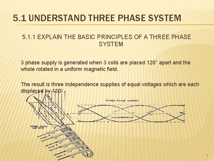
5. 1 UNDERSTAND THREE PHASE SYSTEM 5. 1. 1 EXPLAIN THE BASIC PRINCIPLES OF A THREE PHASE SYSTEM - 3 phase supply is generated when 3 coils are placed 120° apart and the whole rotated in a uniform magnetic field. - The result is three independence supplies of equal voltages which are each displaced by 120°. 4
- The convention adopted to identify each of the phase voltages is : R-red, Y-yellow and B-blue. - The phase sequence is given by the sequence in which the conductors pass the point initially taken by the red conductor. - The national standard phase sequence is R, Y, B. - 2 ways to interconnect the three phases: (a) Star connection (b) Delta connection 5
5. 2 UNDERSTAND THREE PHASE SYSTEM CONFIGURATIONS 5. 2. 1 LIST THE ADVANTAGES AND APPLICATION OF THREE PHASE SYSTEM COMPARED TO SINGLE PHASE SYSTEM APPLICATIONS: - Two voltage are available ( star & delta connection ): (a) Star connection: domestic user (b) Delta connection: industrials user 6
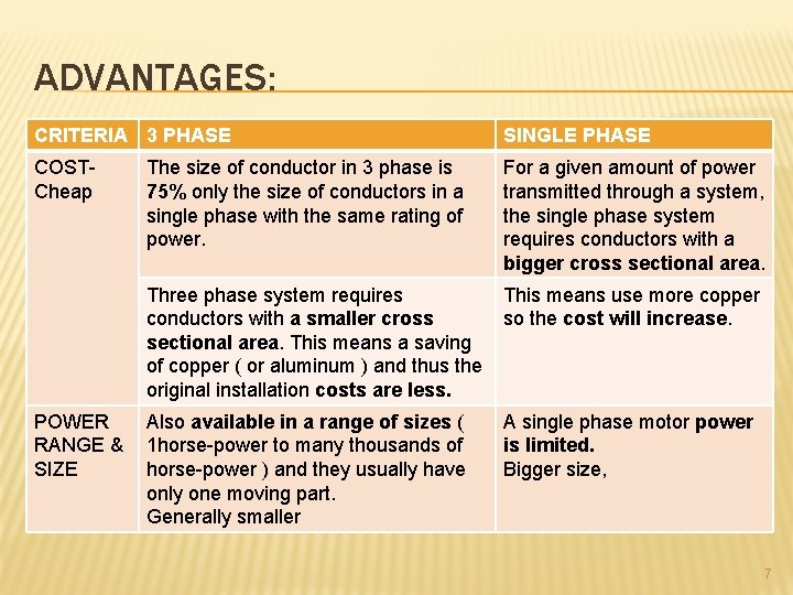
ADVANTAGES: CRITERIA 3 PHASE SINGLE PHASE COST- Cheap For a given amount of power transmitted through a system, the single phase system requires conductors with a bigger cross sectional area. The size of conductor in 3 phase is 75% only the size of conductors in a single phase with the same rating of power. Three phase system requires This means use more copper conductors with a smaller cross so the cost will increase. sectional area. This means a saving of copper ( or aluminum ) and thus the original installation costs are less. POWER Also available in a range of sizes ( RANGE & 1 horse-power to many thousands of SIZE horse-power ) and they usually have only one moving part. Generally smaller A single phase motor power is limited. Bigger size, 7
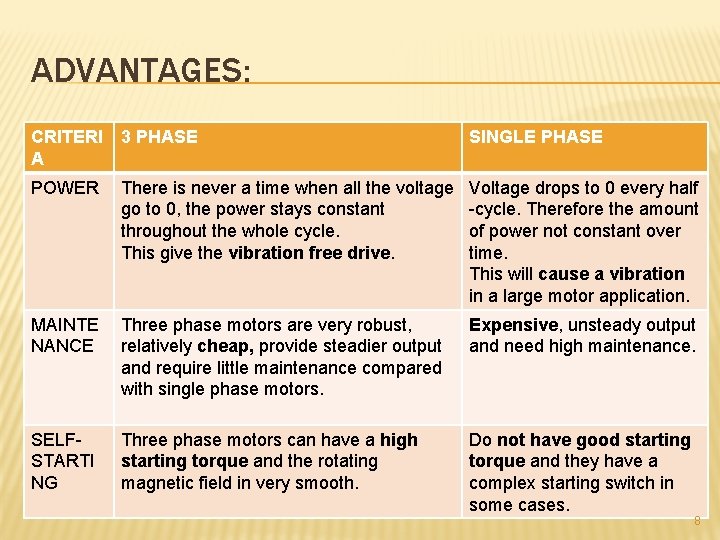
ADVANTAGES: CRITERI A 3 PHASE SINGLE PHASE POWER There is never a time when all the voltage go to 0, the power stays constant throughout the whole cycle. This give the vibration free drive. Voltage drops to 0 every half -cycle. Therefore the amount of power not constant over time. This will cause a vibration in a large motor application. MAINTE NANCE Three phase motors are very robust, relatively cheap, provide steadier output and require little maintenance compared with single phase motors. Expensive, unsteady output and need high maintenance. SELFSTARTI NG Three phase motors can have a high starting torque and the rotating magnetic field in very smooth. Do not have good starting torque and they have a complex starting switch in some cases. 8
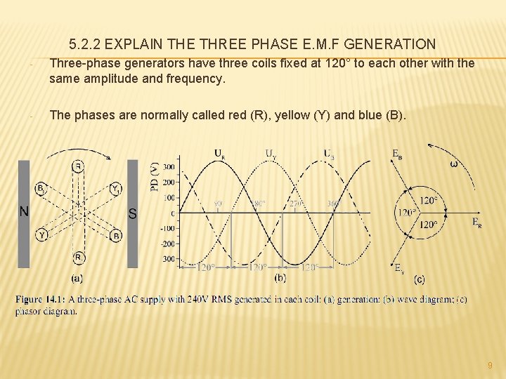
5. 2. 2 EXPLAIN THE THREE PHASE E. M. F GENERATION - Three-phase generators have three coils fixed at 120° to each other with the same amplitude and frequency. - The phases are normally called red (R), yellow (Y) and blue (B). 9
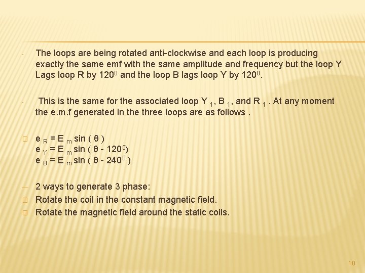
- The loops are being rotated anti-clockwise and each loop is producing exactly the same emf with the same amplitude and frequency but the loop Y Lags loop R by 1200 and the loop B lags loop Y by 1200. - This is the same for the associated loop Y 1, B 1, and R 1. At any moment the e. m. f generated in the three loops are as follows. � e R = E m sin ( θ ) e Y = E m sin ( θ - 1200) e B = E m sin ( θ - 2400 ) ― 2 ways to generate 3 phase: Rotate the coil in the constant magnetic field. Rotate the magnetic field around the static coils. � � 10
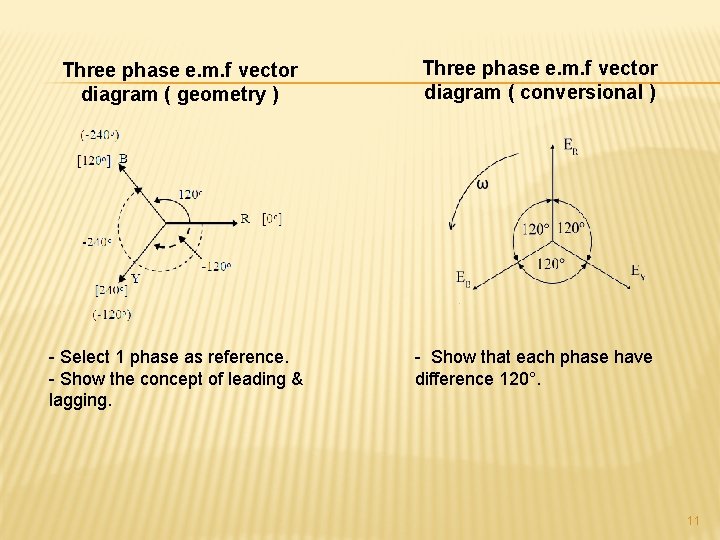
Three phase e. m. f vector diagram ( geometry ) Three phase e. m. f vector diagram ( conversional ) - Select 1 phase as reference. - Show the concept of leading & lagging. - Show that each phase have difference 120°. 11
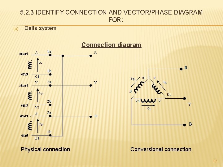
5. 2. 3 IDENTIFY CONNECTION AND VECTOR/PHASE DIAGRAM FOR: (a) Delta system Connection diagram Physical connection Conversional connection 12

Vector diagram 13
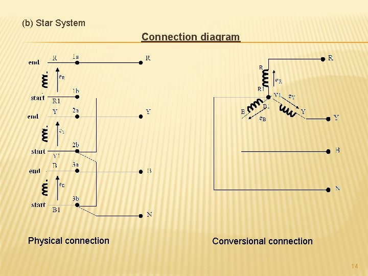
(b) Star System Connection diagram Physical connection Conversional connection 14
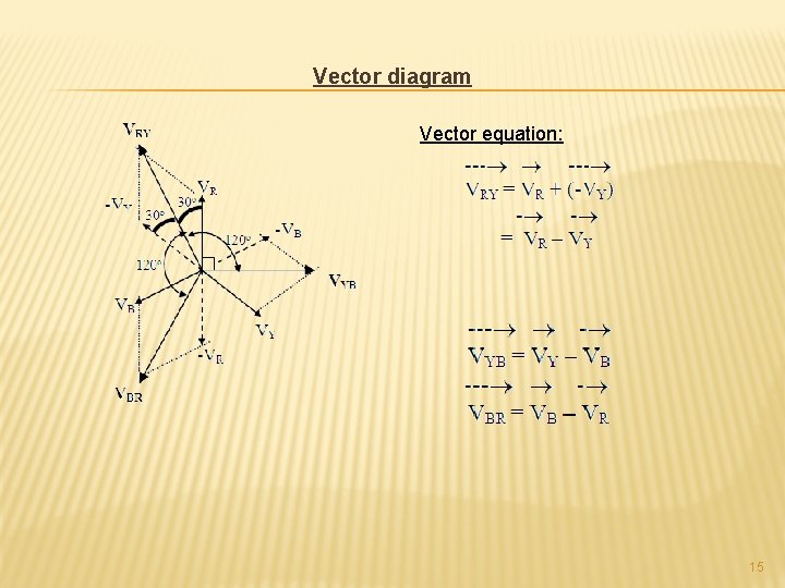
Vector diagram Vector equation: 15
5. 2. 4 DETERMINE THE PHASE VOLTAGE, PHASE CURRENT, LINE VOLTAGE AND LINE CURRENT FOR DELTA AND STAR SYSTEMS Phase voltage (Vph): Voltage induce in each coil Phase current ( Iph) : Current induce in each coil Line voltage ( VL) : Voltage across any two life terminal. Line current ( IL) : Current across any life terminal 16
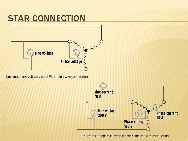
STAR CONNECTION 17
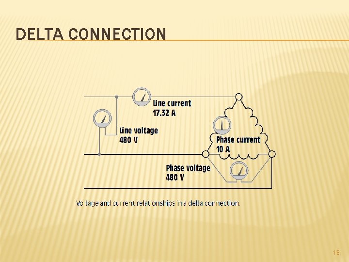
DELTA CONNECTION 18
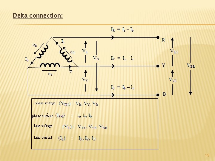
Delta connection: 19
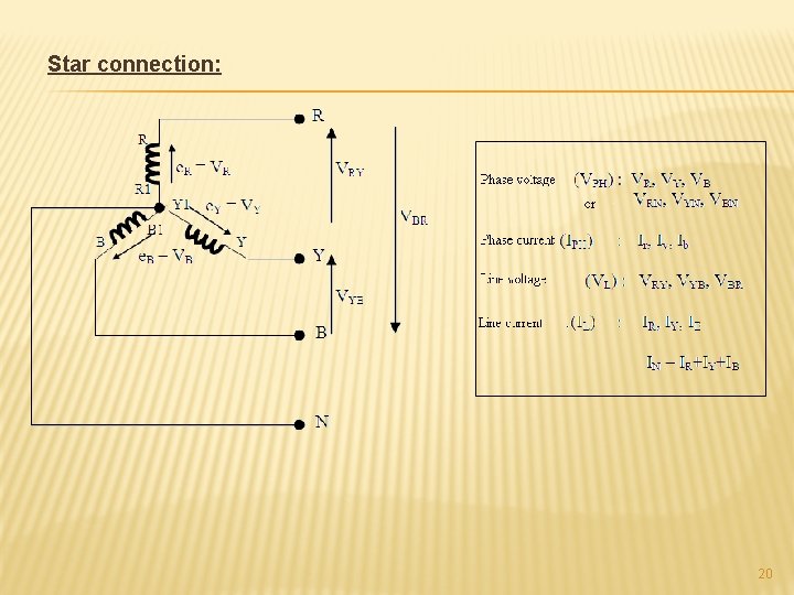
Star connection: 20
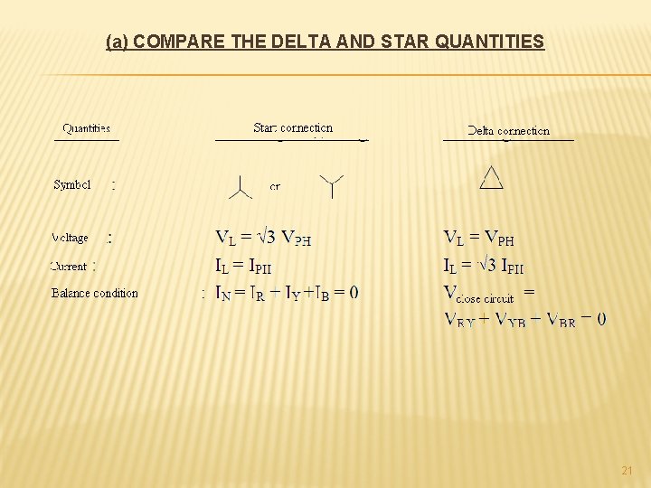
(a) COMPARE THE DELTA AND STAR QUANTITIES 21
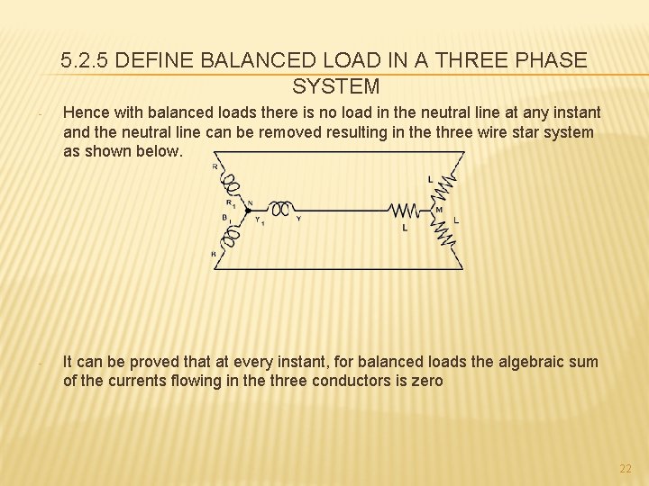
5. 2. 5 DEFINE BALANCED LOAD IN A THREE PHASE SYSTEM - Hence with balanced loads there is no load in the neutral line at any instant and the neutral line can be removed resulting in the three wire star system as shown below. - It can be proved that at every instant, for balanced loads the algebraic sum of the currents flowing in the three conductors is zero 22
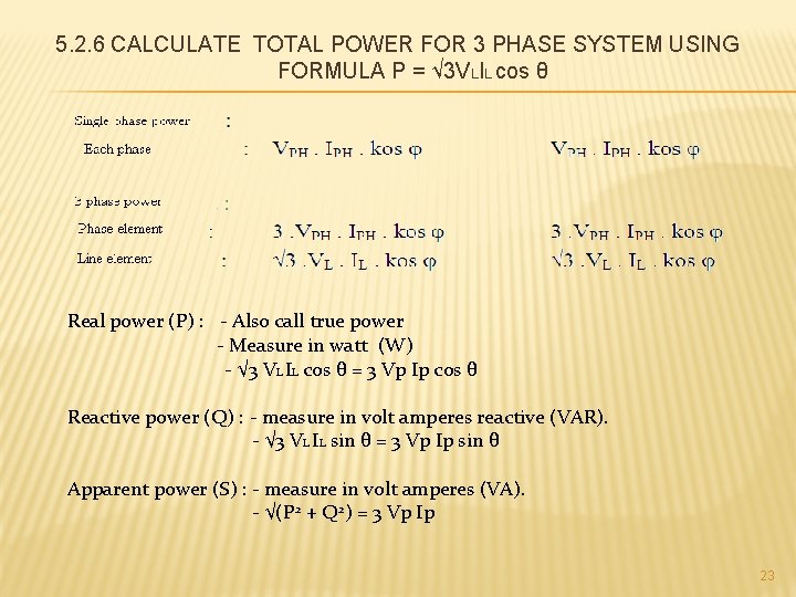
5. 2. 6 CALCULATE TOTAL POWER FOR 3 PHASE SYSTEM USING FORMULA P = √ 3 VLIL cos θ Real power (P) : - Also call true power - Measure in watt (W) - √ 3 VL IL cos θ = 3 Vp Ip cos θ Reactive power (Q) : - measure in volt amperes reactive (VAR). - √ 3 VL IL sin θ = 3 Vp Ip sin θ Apparent power (S) : - measure in volt amperes (VA). - √(P 2 + Q 2) = 3 Vp Ip 23
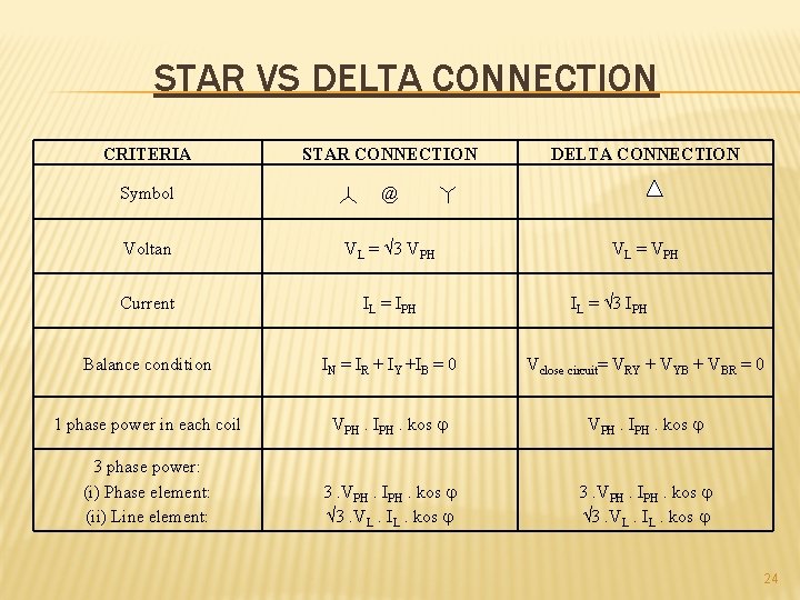
STAR VS DELTA CONNECTION CRITERIA STAR CONNECTION DELTA CONNECTION Symbol @ Voltan VL = 3 VPH Current IL = IPH Balance condition IN = IR + IY +IB = 0 Vclose circuit= VRY + VYB + VBR = 0 1 phase power in each coil VPH. IPH. kos 3 phase power: (i) Phase element: (ii) Line element: 3. VPH. IPH. kos 3. VL. IL. kos VL = VPH IL = 3 IPH 24
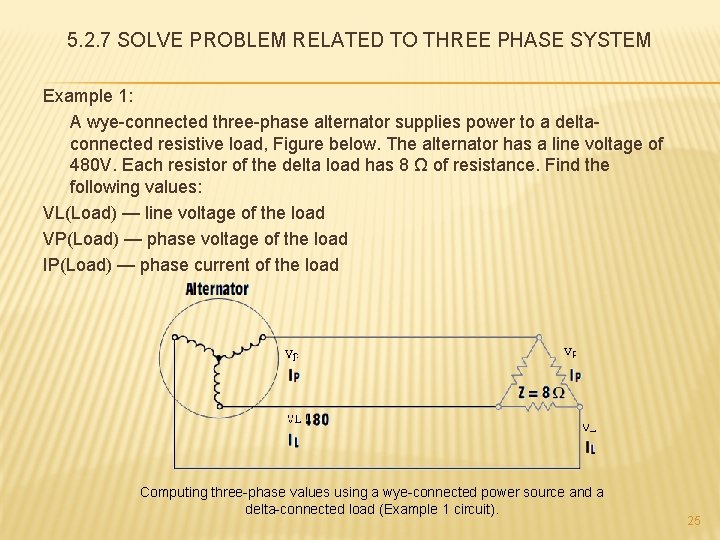
5. 2. 7 SOLVE PROBLEM RELATED TO THREE PHASE SYSTEM Example 1: A wye-connected three-phase alternator supplies power to a deltaconnected resistive load, Figure below. The alternator has a line voltage of 480 V. Each resistor of the delta load has 8 Ω of resistance. Find the following values: VL(Load) — line voltage of the load VP(Load) — phase voltage of the load IP(Load) — phase current of the load Computing three-phase values using a wye-connected power source and a delta-connected load (Example 1 circuit). 25
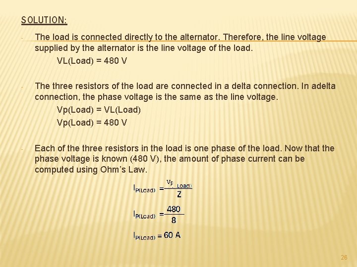
SOLUTION: - The load is connected directly to the alternator. Therefore, the line voltage supplied by the alternator is the line voltage of the load. VL(Load) = 480 V - The three resistors of the load are connected in a delta connection. In adelta connection, the phase voltage is the same as the line voltage. Vp(Load) = VL(Load) Vp(Load) = 480 V - Each of the three resistors in the load is one phase of the load. Now that the phase voltage is known (480 V), the amount of phase current can be computed using Ohm’s Law. 26
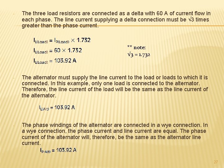
- The three load resistors are connected as a delta with 60 A of current flow in each phase. The line current supplying a delta connection must be √ 3 times greater than the phase current. ** note: √ 3 = 1. 732 - The alternator must supply the line current to the load or loads to which it is connected. In this example, only one load is connected to the alternator. Therefore, the line current of the load will be the same as the line current of the alternator. - The phase windings of the alternator are connected in a wye connection. In a wye connection, the phase current and line current are equal. The phase current of the alternator will, therefore, be the same as the alternator line current. 27
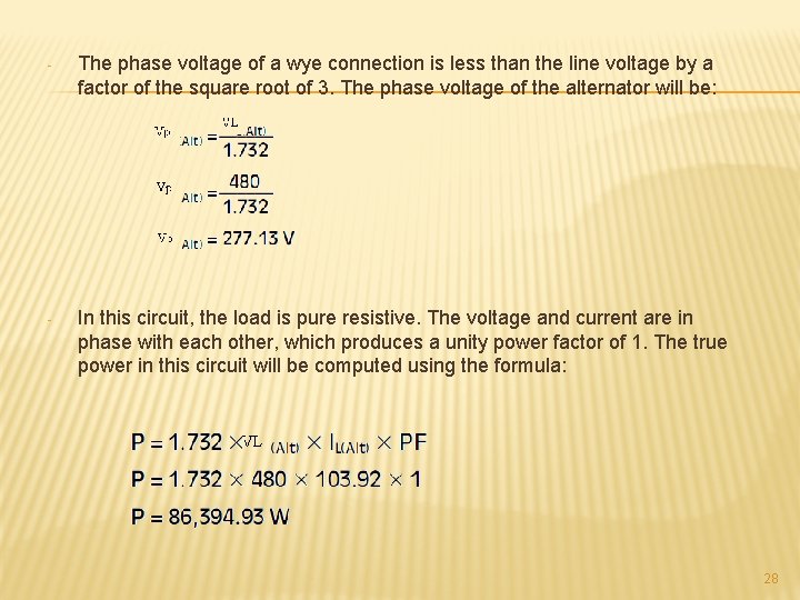
- The phase voltage of a wye connection is less than the line voltage by a factor of the square root of 3. The phase voltage of the alternator will be: - In this circuit, the load is pure resistive. The voltage and current are in phase with each other, which produces a unity power factor of 1. The true power in this circuit will be computed using the formula: 28
- Slides: 28