4 Tool tolerance By Grinding wheel 5 Base

4. Tool tolerance By Grinding wheel

5. Base for assembly Guide for disc or washer assembly Guide for pin assembly

6. Perpendicular Surfaces Tool - Tip curvature of single point cutting tools deforms the corner of the perpendicular surfaces

3 mm 450 d

2 1 1 X 2 1 2 2 1

7. Pin Hole relationship Sharp Corner 450 x 1. 5

L 2 L L 1

A B L A B

8. Avoiding of shoulder by tapered shaft ends - Hub fixation occurs when the contact surface between hub and both of washer and shoulder.

9. Assembly of Elements on Parallel Surfaces Cover Cylinder - Clearance between cover and cylinder is used.

10. Assembly of Elements on Parallel Surfaces - Partial contact between flat contact surfaces is better to avoid effect of out of flatness or distortion.

11. Bases of flat casting Elements - Bases of casting elements in the same level is recommended.

12. General Recommendations by Casting

- Casting of perpendicular surfaces.

- Casting of wheels with webs.

12. Strengthen of Vertical column

12. Strengthen of Vertical column

12. Strengthen of Vertical column

13. Gear Wheels F F F - Improvement of external gear strength by means of strengthening single (A) or double (B) web.

- Improvement of bevel gear strength.

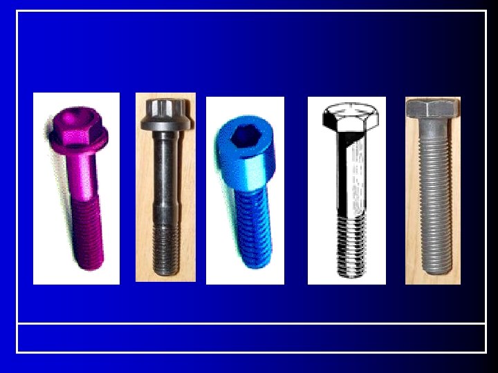
13. Bolts Connections - M 1 : M 8 Each 1 - M 8 : M 24 Each 2 L 1 0. 8 d Bolts series - M 48 Each 4 H (bolt Head) = 0. 7 d H (Nut) = 0. 8 d L 1 = Variable Design- Make Nuts and bolts 0. 7 d - M 24 : M 48 Each 3 2 d d. 5 d 1
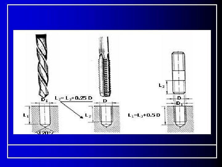
 Hole drilling Drill Work Piece L 1 : Hole Depth")
Bolts Connections 1) Hole drilling Drill Work Piece L 1 : Hole Depth
 Hole drilling 2) Thread Cutting L 2 : Thread Depth L")
Bolts Connections 1) Hole drilling 2) Thread Cutting L 2 : Thread Depth L 3 : Bolt Thread Depth Thread Cutting tool
 Hole drilling 2) Thread Cutting 3) Bolt (Stud) assembly.")
13. Bolts Connections 1) Hole drilling 2) Thread Cutting 3) Bolt (Stud) assembly.

Steps of Stud Assembly Washer Nut

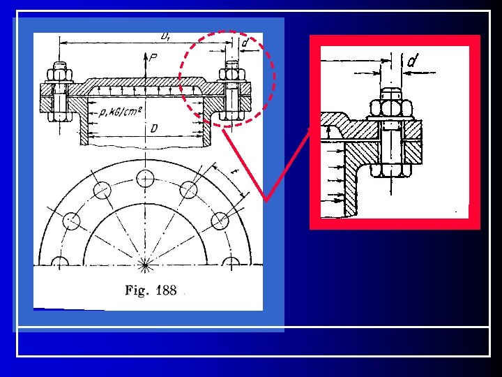
A. Through Bolt DHole = 1. 2 Dbolt • Bolt is under tension. • Elements are under compression.
 • Lower")
B. Tap Bolt • Upper part has a hole (1. 2 d) • Lower part is threaded. • Connection occurs due to the mutual forces between: • 1 - Contact between Bolt head and surface of upper part. • 2 -Teeth of the bolt end

C. Stud Consist of two threaded parts and a cylindrical neck. One end is assembled in the base element and the other element is pressed by a net assembled in the other bolt end. Hole diameter of the upper part is (1. 2 d).

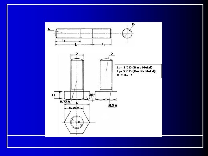
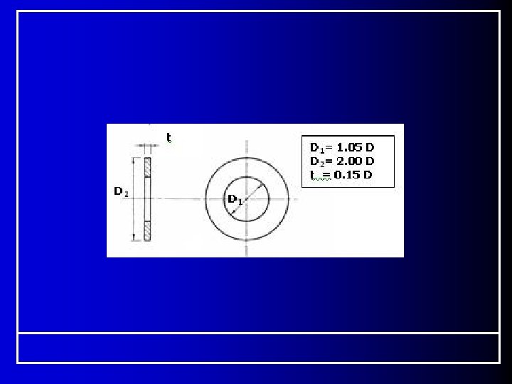
Relative Dimensions of Hole and Bolt D : Bolt Diameter ( D=30 For Bolt M 30) H 1 = 0. 8 D ( Nut Height) t (Washer height) = 0. 15 D D 2 = 2 D ( Washer Biggest width) A = 3 D ( Min. Surface of contact width) L 1 = 2 D +1. 25 (Thread of bolt length) L 2 = L 1 + 0. 25 D (Hole thread length) L 3 = L 1 + 0. 4 D (Hole depth)

Washer placed under nut.

Pressure

A=2 D

Applications

Belts & Pulleys

Belts & Pulleys

Belts & Pulleys Design- 3 D CONVEYOR ANIMATION - FINAL PROJECT -

END
- Slides: 42