
4 G using MIMO Presented by Joel Abraham
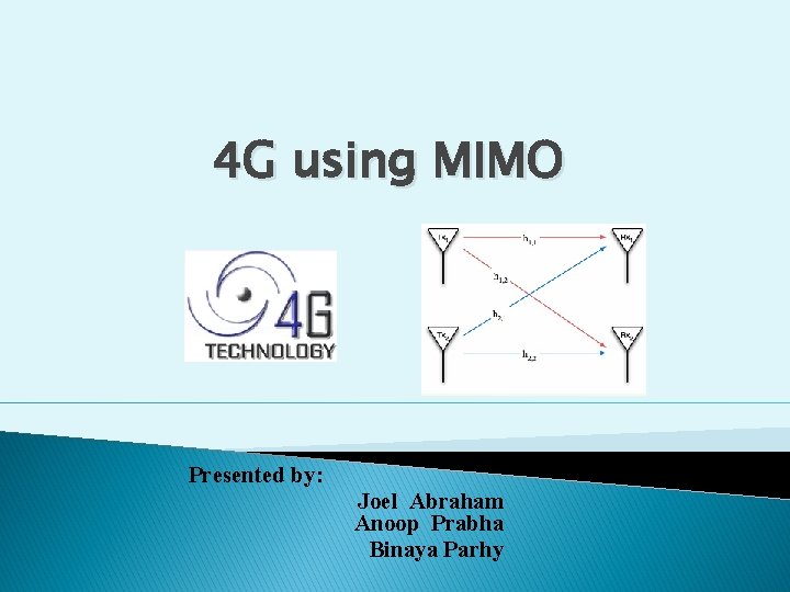
4 G using MIMO Presented by: Joel Abraham Anoop Prabha Binaya Parhy
Agenda � Why MIMO � Different Arrangements of Antennas � Working � MIMO vs SIMO/MISO � Types of MIMO ◦ Diversity ◦ Spatial Multiplexing ◦ Uplink Collaborative MIMO Link � Actual Working � Channel Matrix � System Model � Advantages and Application
Why MIMO ? MIMO is an acronym that stands for Multiple Input Multiple Output. � Motivation: current wireless systems � ◦ Capacity constrained networks ◦ Signal Fading, Multi-path, increasing interference, limited spectrum. MIMO exploits the space dimension to improve wireless systems capacity, range and reliability � MIMO-OFDM – the corner stone of future broadband wireless access � ◦ – Wi. Fi – 802. 11 n ◦ – Wi. MAX – 802. 16 e (a. k. a 802. 16 -2005) ◦ – 3 G / 4 G
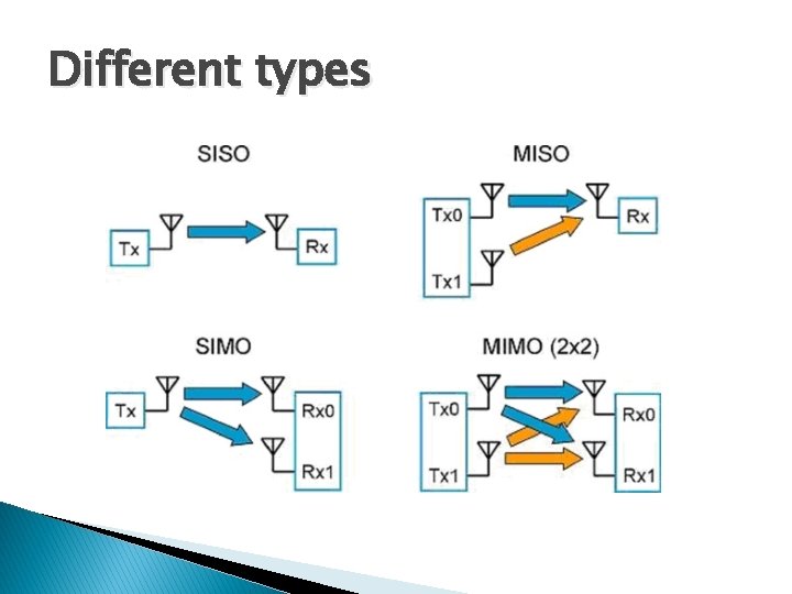
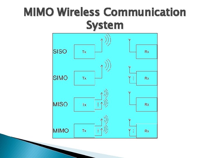
Different types
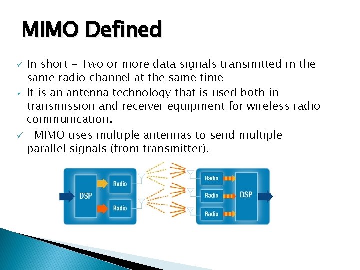
MIMO Defined ü ü ü In short - Two or more data signals transmitted in the same radio channel at the same time It is an antenna technology that is used both in transmission and receiver equipment for wireless radio communication. MIMO uses multiple antennas to send multiple parallel signals (from transmitter).
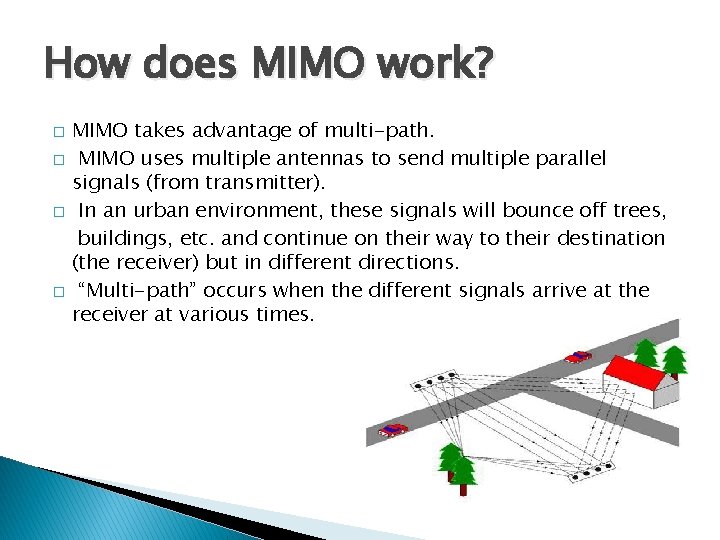
How does MIMO work? � � MIMO takes advantage of multi-path. MIMO uses multiple antennas to send multiple parallel signals (from transmitter). In an urban environment, these signals will bounce off trees, buildings, etc. and continue on their way to their destination (the receiver) but in different directions. “Multi-path” occurs when the different signals arrive at the receiver at various times.
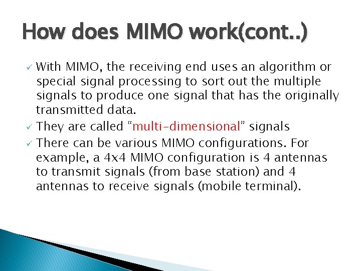
How does MIMO work(cont. . ) With MIMO, the receiving end uses an algorithm or special signal processing to sort out the multiple signals to produce one signal that has the originally transmitted data. ü They are called “multi-dimensional” signals ü There can be various MIMO configurations. For example, a 4 x 4 MIMO configuration is 4 antennas to transmit signals (from base station) and 4 antennas to receive signals (mobile terminal). ü
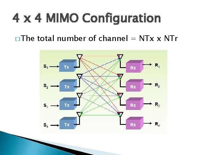
4 x 4 MIMO Configuration � The total number of channel = NTx x NTr
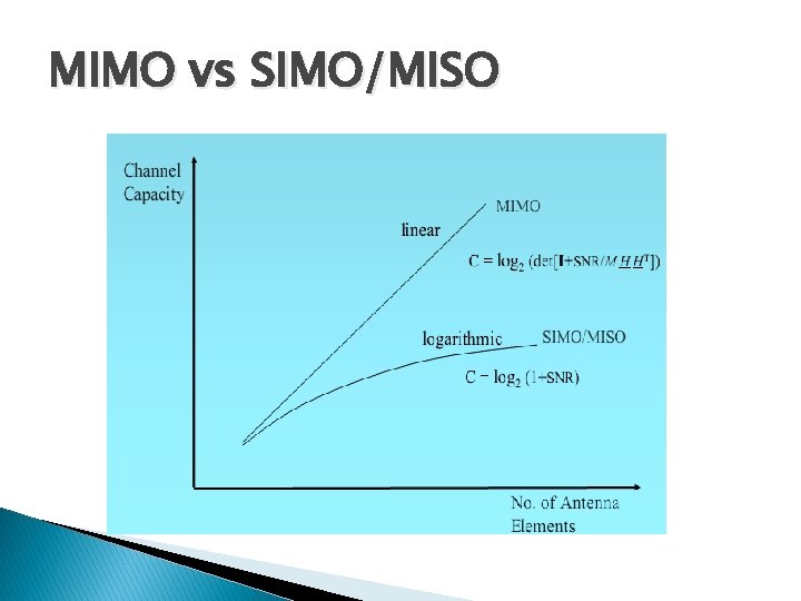
MIMO vs SIMO/MISO
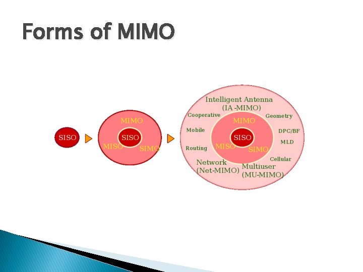
Forms of MIMO
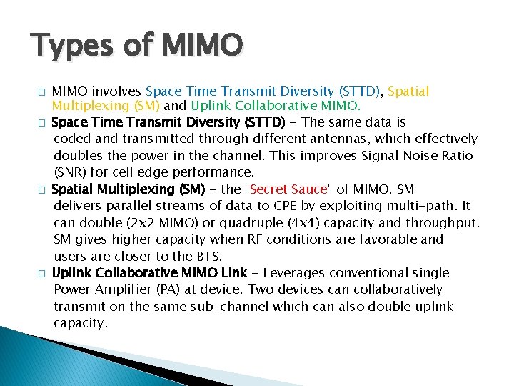
Types of MIMO � � MIMO involves Space Time Transmit Diversity (STTD), Spatial Multiplexing (SM) and Uplink Collaborative MIMO. Space Time Transmit Diversity (STTD) - The same data is coded and transmitted through different antennas, which effectively doubles the power in the channel. This improves Signal Noise Ratio (SNR) for cell edge performance. Spatial Multiplexing (SM) - the “Secret Sauce” of MIMO. SM delivers parallel streams of data to CPE by exploiting multi-path. It can double (2 x 2 MIMO) or quadruple (4 x 4) capacity and throughput. SM gives higher capacity when RF conditions are favorable and users are closer to the BTS. Uplink Collaborative MIMO Link - Leverages conventional single Power Amplifier (PA) at device. Two devices can collaboratively transmit on the same sub-channel which can also double uplink capacity.
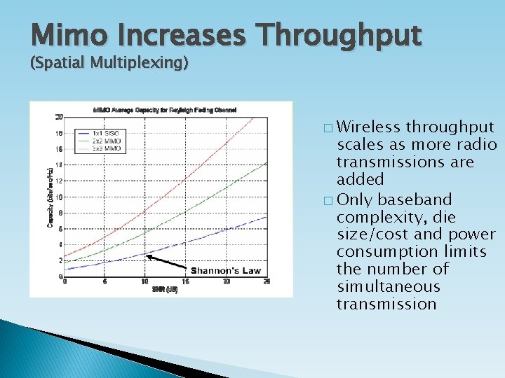
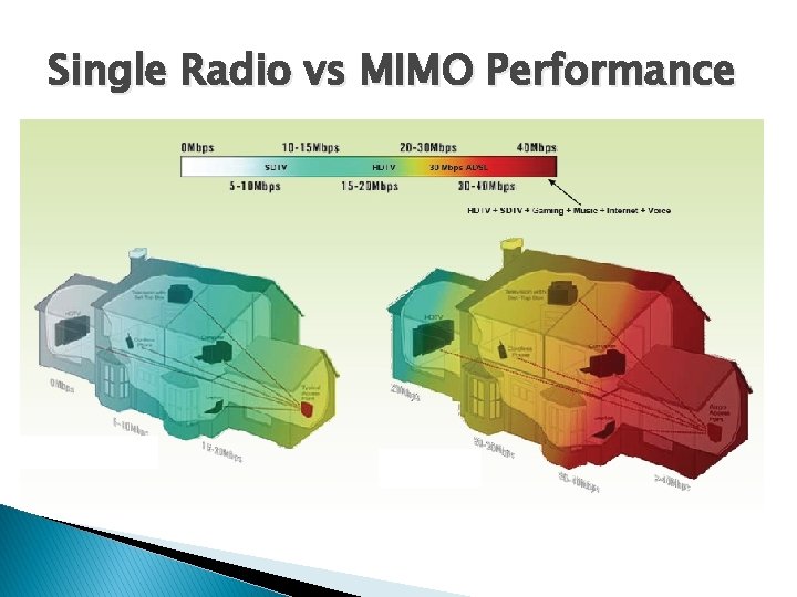
Mimo Increases Throughput (Spatial Multiplexing) � Wireless throughput scales as more radio transmissions are added � Only baseband complexity, die size/cost and power consumption limits the number of simultaneous transmission
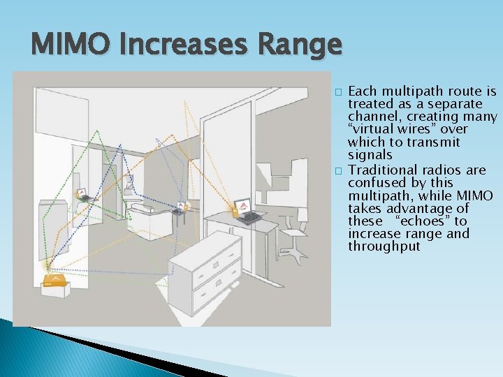
MIMO Increases Range � � Each multipath route is treated as a separate channel, creating many “virtual wires” over which to transmit signals Traditional radios are confused by this multipath, while MIMO takes advantage of these “echoes” to increase range and throughput
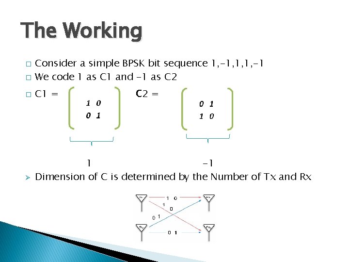
The Working � Consider a simple BPSK bit sequence 1, -1, 1, 1, -1 We code 1 as C 1 and -1 as C 2 � C 1 = Ø 1 -1 Dimension of C is determined by the Number of Tx and Rx � c 2 =
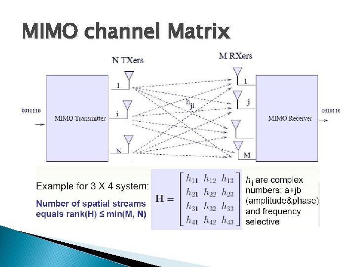
MIMO channel Matrix
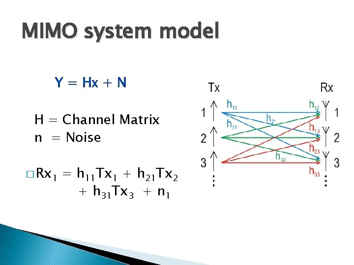
MIMO system model H = Channel Matrix n = Noise � Rx 1 = h 11 Tx 1 + h 21 Tx 2 + h 31 Tx 3 + n 1
Single Radio vs MIMO Performance
General Info & Application � Using the space dimension (MIMO) to boost data rates up to 600 Mbps through multiple antennas and signal processing. � Target applications include: large files backup, HD streams, online interactive gaming, home entertainment, etc. � Backwards compatible with 802. 11 a/b/g � Application ◦ ◦ ◦ WLAN – Wi. Fi 802. 11 n Mesh Networks (e. g. , Muni. Wireless) WMAN – Wi. MAX 802. 16 e 4 G RFID Digital Home

References � � � http: //en. wikipedia. org/wiki/4 G http: //en. wikipedia. org/wiki/MIMO#MIMO_literature http: //www. wirelessnetdesignline. com/howto/wlan/185300393; jsessionid=3 R 20 PO 41 A V 3 Y 1 QE 1 GHRSKHWATMY 32 JVN? pgno=1 www. ieeeexplore. com http: //www. ece. ualberta. ca/~HCDC/mimohistory. html http: //citeseerx. ist. psu. edu/viewdoc/download? doi=10. 1. 1. 13. 4732&rep=rep 1&type=p df
Thank you
Presented By Anoop Madhusoodhanan Prabha 36576876
Distribution of Fading channel Rayleigh Model ü Statistical Modeling of wireless channels. ü Magnitude of signal varies randomly as it propagates in the medium. ü Best fit for tropospheric and ionospheric signal propagation. ü Fits fine for Urban environments too. ü Highlight – No dominant light of sight communication between transmitter and receiver. ü Rate of channel fade – Studied by Doppler shift. 10 Hz to 100 Hz is the shift considered in GSM phones modeling for an operating frequency of 1800 MHz and speed between 6 km/h to 60 km/h Ø
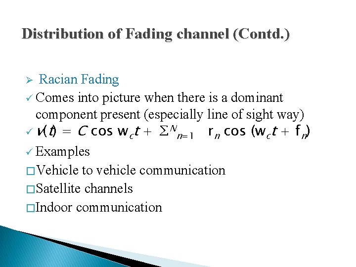
Distribution of Fading channel (Contd. ) Ø Racian Fading ü Comes into picture when there is a dominant component present (especially line of sight way) ü v(t) = C cos wct + ∑Nn=1 rn cos (wct + fn) ü Examples � Vehicle to vehicle communication � Satellite channels � Indoor communication
Distribution of Fading Channel (Contd. ) Ø Nakagami fading ü Reason for modeling – Empirical results matched with short wave ionospheric propagation. ü If amplitude – Nakagami distributed, power – gamma distributed and ‘m’ is the shape factor in this distribution. ü For m=1, its Rayleigh fading (amplitude distribution) and corresponding power distribution is exponential. ü These days many recent papers recommend this model as an approx. to Rician model.

Evolution of MIMO Ø The fading and shadowing effects are overcome by spatial diversity i. e. my installing multiple antennas. Ø Antennas separated by 4 – 10 times the wavelength to ensure unique propagation paths. Ø As a part 4 G, one of important emphasis is on throughput improvement. Ø This stressed on better modulation techniques and coding practices.
MIMO Architecture
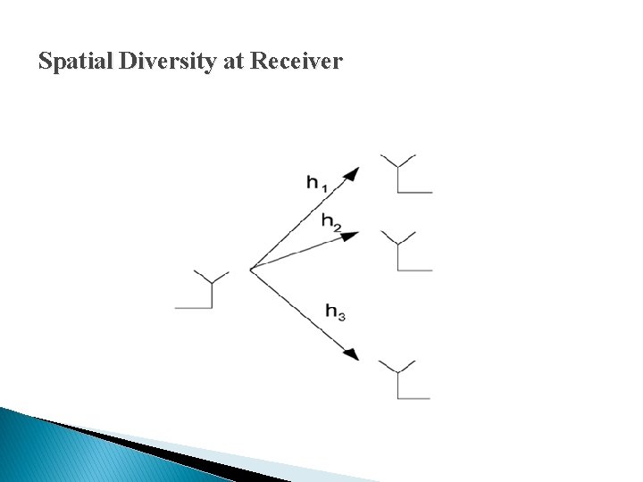
Spatial Diversity at Receiver
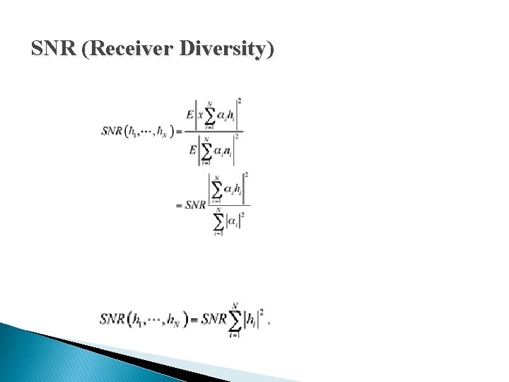
SNR (Receiver Diversity)
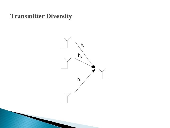
Transmitter Diversity
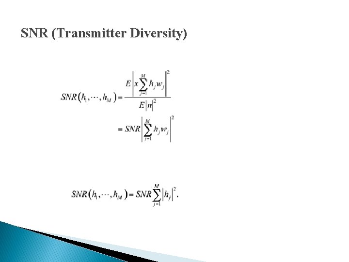
SNR (Transmitter Diversity)
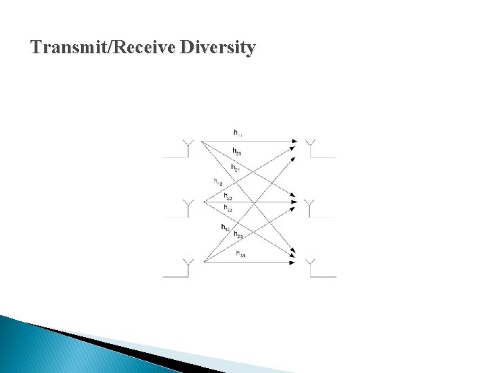
Transmit/Receive Diversity
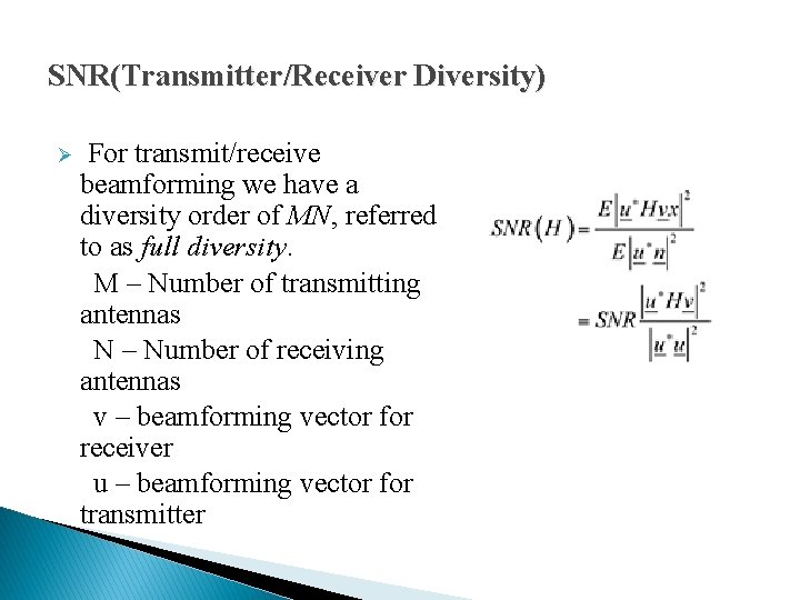
SNR(Transmitter/Receiver Diversity) For transmit/receive beamforming we have a diversity order of MN, referred to as full diversity. M – Number of transmitting antennas N – Number of receiving antennas v – beamforming vector for receiver u – beamforming vector for transmitter Ø
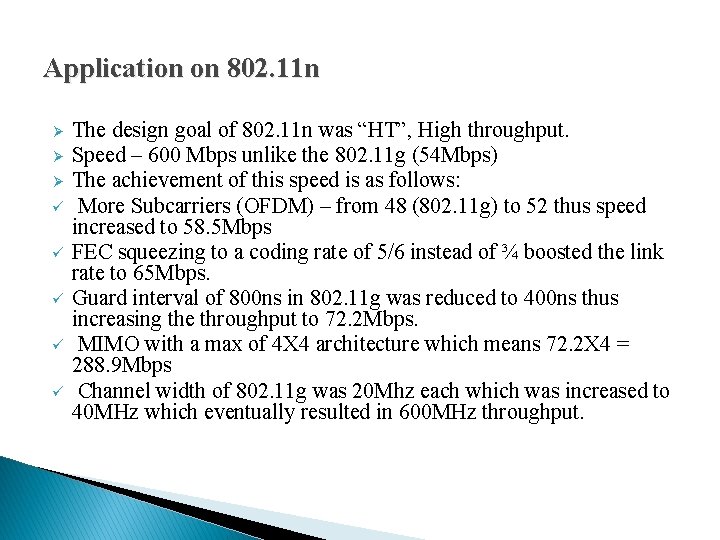
Application on 802. 11 n Ø Ø Ø ü ü ü The design goal of 802. 11 n was “HT”, High throughput. Speed – 600 Mbps unlike the 802. 11 g (54 Mbps) The achievement of this speed is as follows: More Subcarriers (OFDM) – from 48 (802. 11 g) to 52 thus speed increased to 58. 5 Mbps FEC squeezing to a coding rate of 5/6 instead of ¾ boosted the link rate to 65 Mbps. Guard interval of 800 ns in 802. 11 g was reduced to 400 ns thus increasing the throughput to 72. 2 Mbps. MIMO with a max of 4 X 4 architecture which means 72. 2 X 4 = 288. 9 Mbps Channel width of 802. 11 g was 20 Mhz each which was increased to 40 MHz which eventually resulted in 600 MHz throughput.

References Ø http: //www. wirelesscommunication. nl/ Ø Wikipedia Ø http: //www. intel. com/technology/itj/2006/volume 10 i ssue 02/art 07_mimo_architecture/p 04_mimo_systems _reliability. htm Ø http: //www. wirevolution. com
Presented By Binaya Parhy
MIMO Wireless Communication System
Agenda ü ü ü MIMO Wireless Communications Capacity of MIMO Well known STBC codes – – – Criteria to be a good ST BC code. Cyclic and Unitary STBC Orthogonal STBC Diagonal algebric BLAST(V-BLAST & D-BLAST) Differential STBC(Non coherent detection) Summarize
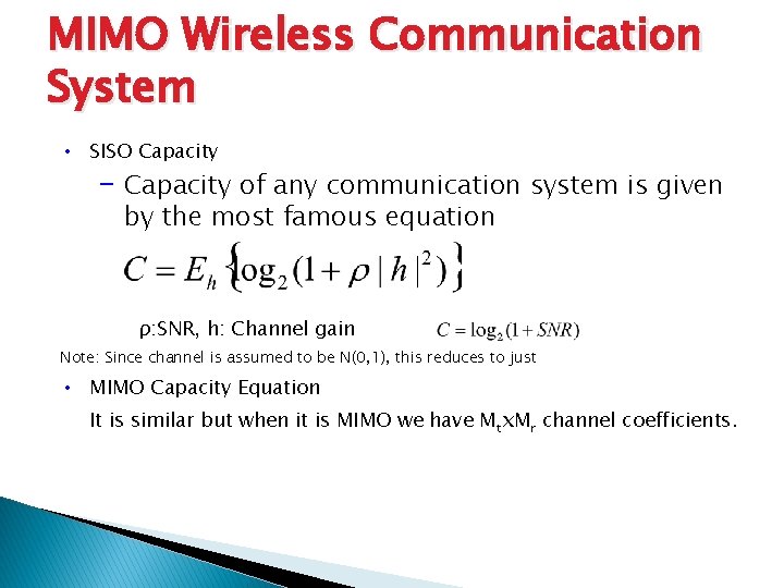
MIMO Wireless Communication System • SISO Capacity – Capacity of any communication system is given by the most famous equation ρ: SNR, h: Channel gain Note: Since channel is assumed to be N(0, 1), this reduces to just • MIMO Capacity Equation It is similar but when it is MIMO we have Mtx. Mr channel coefficients.
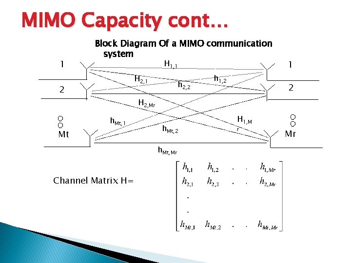
MIMO Capacity cont… 1 Block Diagram Of a MIMO communication system H 1, 1 H 2, 1 2 h 2, 2 h 1, 2 1 2 H 2, Mr h. Mt, 1 Mt h. Mt, 2 h. Mt, Mr Channel Matrix H= H 1, M r Mr
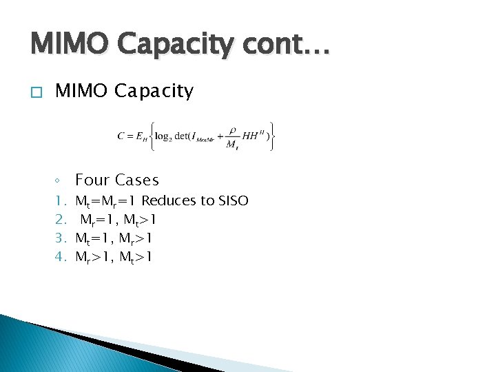
MIMO Capacity cont… � MIMO Capacity ◦ Four Cases 1. 2. 3. 4. Mt=Mr=1 Reduces to SISO Mr=1, Mt>1 Mt=1, Mr>1, Mt>1
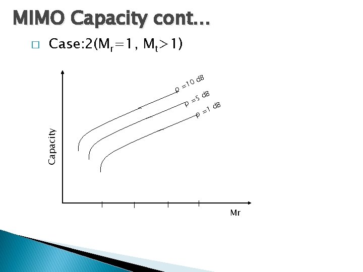
MIMO Capacity cont… Case: 2(Mr=1, Mt>1) ρ= d 10 ρ B d =5 B 1 ρ= d. B Capacity � Mr
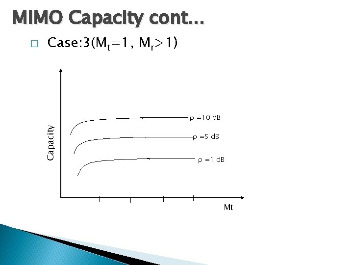
MIMO Capacity cont… Case: 3(Mt=1, Mr>1) ρ =10 d. B Capacity � ρ =5 d. B ρ =1 d. B Mt
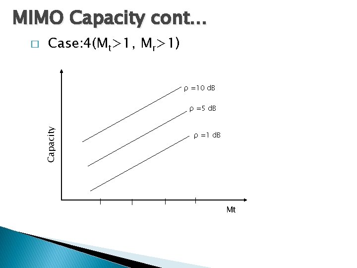
MIMO Capacity cont… Case: 4(Mt>1, Mr>1) ρ =10 d. B ρ =5 d. B Capacity � ρ =1 d. B Mt
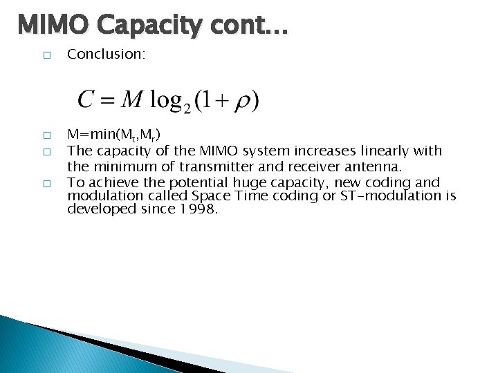
MIMO Capacity cont… � � Conclusion: M=min(Mt, Mr) The capacity of the MIMO system increases linearly with the minimum of transmitter and receiver antenna. To achieve the potential huge capacity, new coding and modulation called Space Time coding or ST-modulation is developed since 1998.
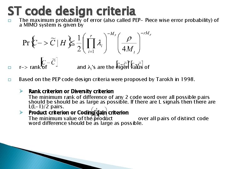
ST code design criteria � The maximum probability of error (also called PEP- Piece wise error probability) of a MIMO system is given by � r-> rank of � Based on the PEP code design criteria were proposed by Tarokh in 1998. Ø Ø and λi’s are the eigen valus of Rank criterion or Diversity criterion The minimum rank of difference of any 2 code word over all possible pairs should be as large as possible. If there are L signals then there are L(L-1)/2 pairs. Product criterion or Coding gain criterion The minimum value of the product over all pairs of distinct code word difference should be as large as possible.
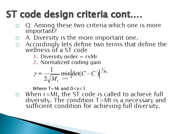
ST code design criteria cont…. � � � Q: Among these two criteria which one is more important? A: Diversity is the more important one. Accordingly lets define two terms that define the wellness of a ST code 1. Diversity order = rx. Mr 2. Normalized coding gain Where T=Mt and 0<γ<1 � When r=Mt, the ST code is called to achieve full diversity. The condition T=Mt is a necessary and sufficient condition for achieving full diversity.
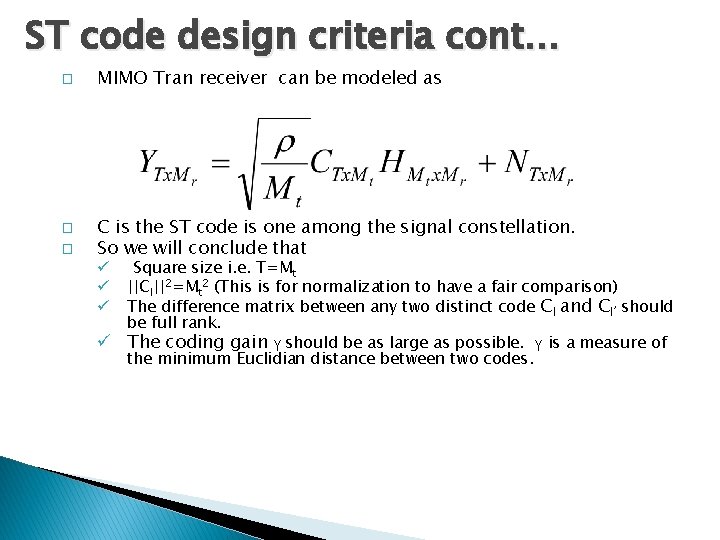
ST code design criteria cont… � � � MIMO Tran receiver can be modeled as C is the ST code is one among the signal constellation. So we will conclude that Square size i. e. T=Mt ||Cl||2=Mt 2 (This is for normalization to have a fair comparison) The difference matrix between any two distinct code Cl and Cl’ should be full rank. ü The coding gain γ should be as large as possible. γ is a measure of the minimum Euclidian distance between two codes. ü ü ü
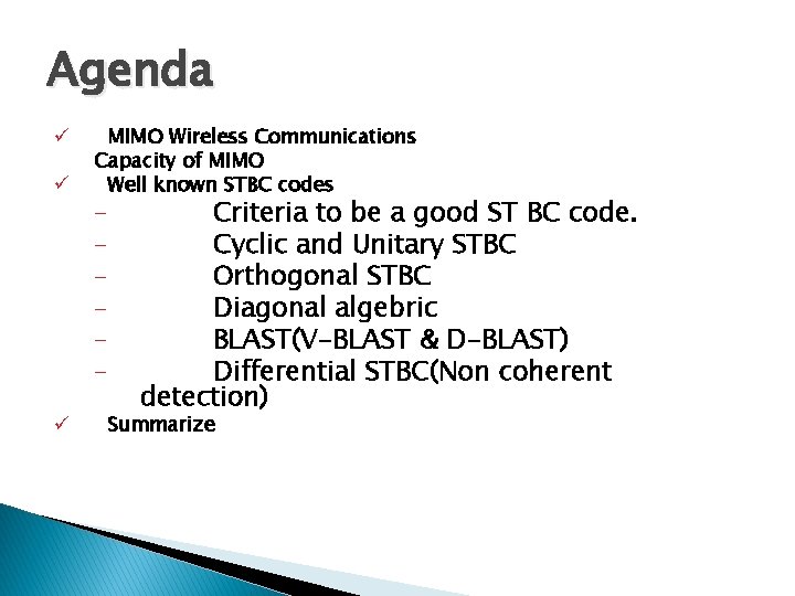
Some well known ST signals Ø Cyclic and Unitary STBC Ø Orthogonal STBC Ø Diagonal algebric Ø BLAST(V-BLAST & D-BLAST) Ø Differential STBC(Non coherent detection)
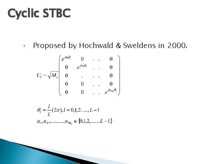
Cyclic STBC • Proposed by Hochwald & Sweldens in 2000.
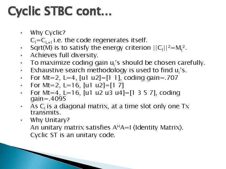
Cyclic STBC cont… • • • Why Cyclic? Cl=CL+l i. e. the code regenerates itself. Sqrt(M) is to satisfy the energy criterion ||Cl||2=Mt 2. Achieves full diversity. To maximize coding gain ui’s should be chosen carefully. Exhaustive search methodology is used to find ui’s. For Mt=2, L=4, [u 1 u 2]=[1 1], coding gain=. 707 For Mt=2, L=16, [u 1 u 2]=[1 7] For Mt=4, L=16, [u 1 u 2 u 3 u 4]=[1 3 5 7], coding gain=. 4095 As Cl is a diagonal matrix, at a time slot only one Tx transmits. Why Unitary? An unitary matrix satisfies AHA=I (Identity Matrix). Cyclic ST is an unitary code.
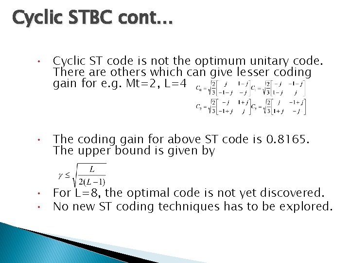
Cyclic STBC cont… • Cyclic ST code is not the optimum unitary code. There are others which can give lesser coding gain for e. g. Mt=2, L=4 • The coding gain for above ST code is 0. 8165. The upper bound is given by • For L=8, the optimal code is not yet discovered. • No new ST coding techniques has to be explored.
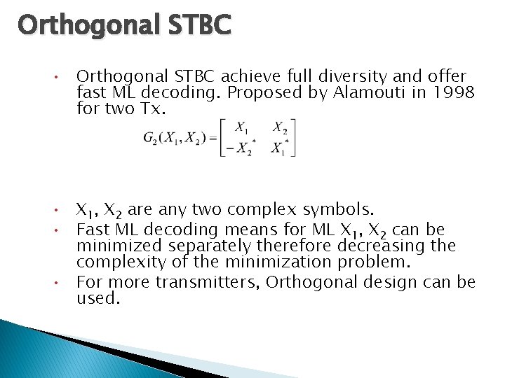
Orthogonal STBC • Orthogonal STBC achieve full diversity and offer fast ML decoding. Proposed by Alamouti in 1998 for two Tx. • X 1, X 2 are any two complex symbols. • Fast ML decoding means for ML X 1, X 2 can be minimized separately therefore decreasing the complexity of the minimization problem. • For more transmitters, Orthogonal design can be used.

Orthogonal STBC cont…. . • Orthogonal design with k variables X 1, X 2, …… Xk is a pxn matrix such that • The entries of G are 0, +/- X 1, +/- X 2 , ……. , +/Xk or their conjugates. • The columns are orthogonal to each other. i. e. • n is related to the number of transmitter antenna and p to the time delay. • The rate of orthogonal design is k/p i. e a code word of time delay p carries k information symbols.
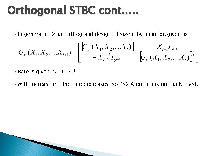
Orthogonal STBC cont…. . • In general n=2 l an orthogonal design of size n by n can be given as • Rate is given by l+1/2 l • With increase in l the rate decreases, so 2 x 2 Alemouti is normally used.
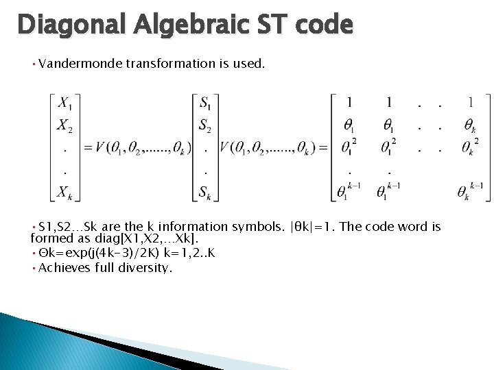
Diagonal Algebraic ST code • Vandermonde transformation is used. • S 1, S 2…Sk are the k information symbols. |θk|=1. The code word is formed as diag[X 1, X 2, …Xk]. • Θk=exp(j(4 k-3)/2 K) k=1, 2. . K • Achieves full diversity.
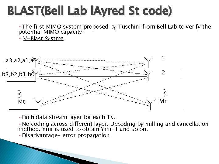
BLAST(Bell Lab l. Ayred St code) • The first MIMO system proposed by Tuschini from Bell Lab to verify the potential MIMO capacity. • V-Blast Systme. . a 3, a 2, a 1, a 0 . b 3, b 2, b 1, b 0 Mt 1 2 Mr • Each data stream layer for each Tx. • No coding across different layer. Decoding by nulling and cancellation method. Ymr is used to obtain Ymr-1 and so on. • Disadvantage- error propagation.
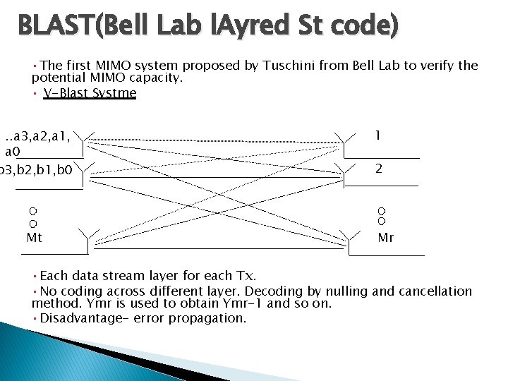
BLAST(Bell Lab l. Ayred St code) • The first MIMO system proposed by Tuschini from Bell Lab to verify the potential MIMO capacity. • V-Blast Systme . . a 3, a 2, a 1, a 0 b 3, b 2, b 1, b 0 Mt 1 2 Mr • Each data stream layer for each Tx. • No coding across different layer. Decoding by nulling and cancellation method. Ymr is used to obtain Ymr-1 and so on. • Disadvantage- error propagation.
D BLAST • Coding is done with in each data stream but no coding across different streams. • At the 1 st time slot only 1 transmitted sends other send nothing. At 2 nd only 1 st and 2 nd Tx sends and so on. After Mt time slots all Tx starts sending. • Achieves full diversity. • Better performance than V-Bl. AST. • Decoding is same as V-BLAST.
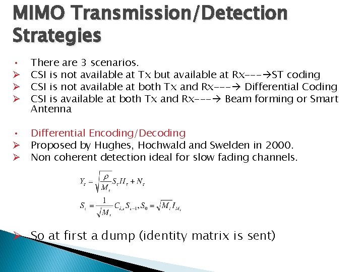
MIMO Transmission/Detection Strategies • Ø Ø Ø There are 3 scenarios. CSI is not available at Tx but available at Rx--- ST coding CSI is not available at both Tx and Rx--- Differential Coding CSI is available at both Tx and Rx--- Beam forming or Smart Antenna • Differential Encoding/Decoding Ø Proposed by Hughes, Hochwald and Swelden in 2000. Ø Non coherent detection ideal for slow fading channels. Ø So at first a dump (identity matrix is sent)
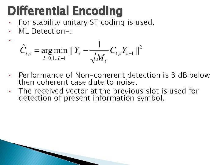
Differential Encoding • For stability unitary ST coding is used. • ML Detection-: • • Performance of Non-coherent detection is 3 d. B below then coherent case dute to noise. • The received vector at the previous slot is used for detection of present information symbol.
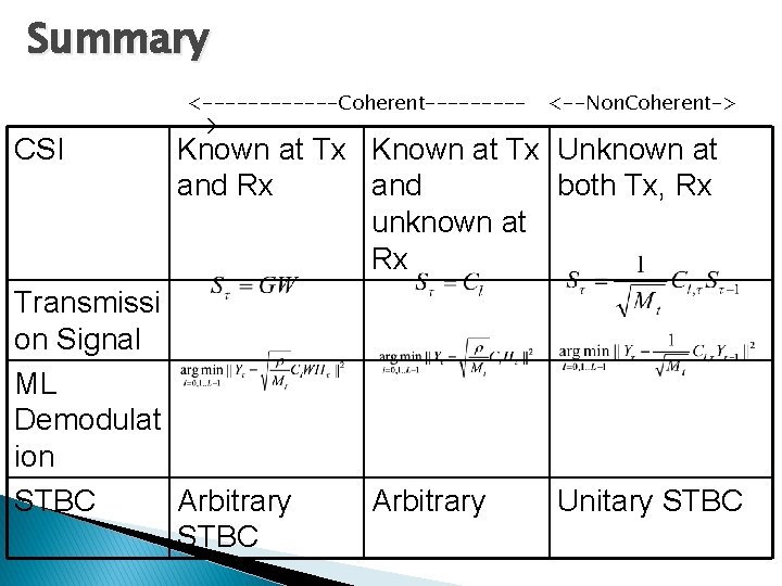
Summary CSI <------Coherent----- <--Non. Coherent-> Known at Tx Unknown at and Rx and both Tx, Rx unknown at Rx Transmissi on Signal ML Demodulat ion STBC Arbitrary Unitary STBC
- Slides: 61