4 3 MEMBER OR ELEMENT STIFFNESS MATRIX FOR

4. 3 MEMBER OR ELEMENT STIFFNESS MATRIX FOR A BEAM / FRAME ELEMENT SUBJECTED TO MOMENTS ONLY: The element stiffness matrix for members whose ends cannot translate but can rotate is obtained by removing third and fourth row corresponding to 3, 4 and third and fourth columns corresponding to w 3 and w 4 from the above mentioned element stiffness matrix of equation 4. 36 as shown below: - The resulting stiffness matrix for a beam element is as follows: --------------(4. 38)

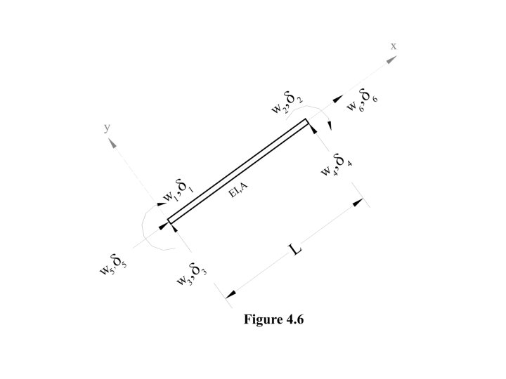
And the force stiffness deformation relationship for a beam element is as fallows: -------------- - (4. 39) 4. 4 MEMBER OR ELEMENT STIFFNESS MATRIX OF A FRAME ELEMENT SUBJECTED TO AXIAL LOADING IN ADDITION TO SHEARING FORCES AND BENDING MOMENTS. The final element that is capable of axial loading in addition to shear forces and bending moments is now considered. The stiffness matrix for this element can be formed by superposition of the element stiffness matrix of truss element and frame element formed as given in the equations 2. 16 and 4. 20. Figure 4. 6 defines the positive forces (axial forces, shear forces and bending moments) and deformations (axial deformations, vertical translations and rotations) for the element.

By superposition of equation 2. 16 and 4. 36. The following element stiffness matrix for six element forces and deformations is obtained. -------- (4. 40)
")
And the force, stiffness and deformation relationship is as under: ---- (4. 41)

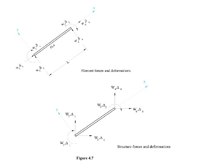
4. 5 DEFORMATION TRANSFORMATION MATRIX: As discussed in the case of trusses, deformation transformation matrix is used to transform the element deformations from local coordinates to structure deformations in global co-ordinates. Using this deformation transformation matrix structure stiffness matrix is obtained as given in the following equation: [K]m = [T]Tm [k]m [T]m ----------- (3. 3) 4. 5. 1 DEFORMATION TRANSFORMATION MATRIX OF A FRAME ELEMENT SUBJECTED TO AXIAL FORCE, SHEAR FORCE AND BENDING MOMENT. A deformation transformation matrix will also be developed to carry out the transformation from element to global coordinates. Consider the frame member shown in figure 4. 7. Member axis, xaxis of member coordinate system makes an angle x with x-axis of the structure coordinate system as shown in figure 4. 7 (b), similarly member axis, x-axis of member coordinate system makes angle y with y-axis of the structure coordinate system. The cosines of these angles are given below l= Cos x m = Cos y

Again consider the frame member shown in figure 4. 7, 1 and 2 are the element deformations (rotation) whereas 1 and 2 are the structure deformations (rotations). As Z-axes for both element and structure coincides, therefore both element and structure rotations will be the same when structure deformation 1 = 1, then the element deformation ---------------- (4. 43) and when structure deformation 2 = 1, then the element deformations ---------------- (4. 44)

Relationship between structure and element deformations can also be obtained in the similar manner for a unit vertical translation of the left end i. e. 3 = 1 (see figure 4. 8) 3 = 3. Cos x, 5 = 3. Cos y 3 = 1. Cos x, 5 = 1. Cos y 3=1. = , 5=1. m=m FIGURE 4. 8 5= 3 Cos y=1. m=m 3= 3 Cos x=1. l=l 1= 2= 4= 6=0 ----------- (4. 45)

Figure 4. 9 4= 4 Cos x=1. l=l 6= 4 Cos y=1. m=m 1= 2= 3= 5=0

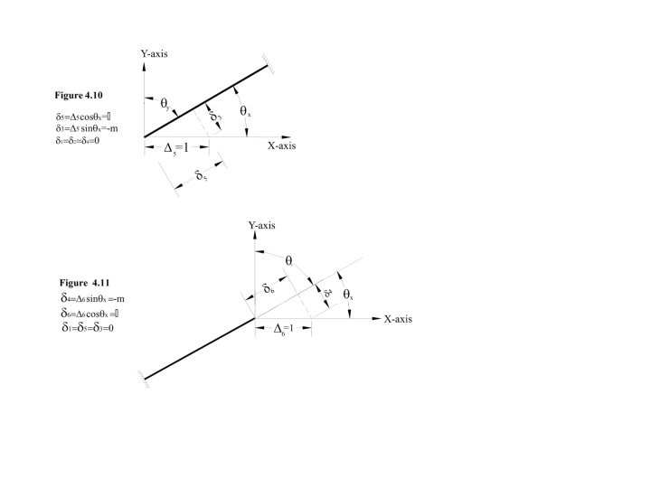
For a unit vertical translation of the right end i. e. 4 = 1 (Fig. 4. 9) element deformations are as under: ---------------- (4. 46) where 3 and 4 are vertical translations of the element. for a unit horizontal translation (along x-axis) of the left end. i-e; 5=1 (4. 47) (Fig. 4. 10) ----------------element deformations are as under: - ---------- (4. 47)

For a unit horizontal translation the right end I-e; 6 = 1, element deformations are as under: - ---------------- (4. 48)
 = T -----------------")
Writing the above six equations in matrix form. ---------------- (4. 49) = T ----------------- (3. 2) Comparing equation (4. 49) with equation (3. 2) deformation transformation matrix (T) is obtained which is as follows: ---------- (4. 50)

This is the deformation transformation matrix of a frame element subjected to shear force, bending moment and axial forces. To obtain the deformation transformation matrix of a beam/frame element subjected only to shear force and bending moment, the axial deformations are ignored. Therefore by deleting last two rows and last two columns of the matrix in equation (4. 50) following deformation transformation matrix is obtained: ---------------- (4. 51) Similarly to obtain the deformation transformation matrix of a beam/frame element subjected only to bending moment, the axial and shear deformations are ignored Therefore by deleting last two rows and last two columns of the matrix in equation (4. 51) following deformation transformation matrix is obtained: ---------------- (4. 52)

4. 6 STRUCTURE STIFFNESS MATRICES 4. 6. 1 For a beam/frame element subjected to bending moment only: Using the element stiffness matrix and deformation transformation matrix structure stiffness matrix is formed. Following equation is used for this purpose: [K]m = [T]Tm [k]m [T]m -------------- (4. 53) Where, [T]m = Deformation Transformation matrix [k]m = Element stiffness matrix In this case: ---------------- (4. 52) And and ---------------- (4. 38)
 and solving, following structure stiffness matrix is")
Substituting these values in equation (4. 53) and solving, following structure stiffness matrix is obtained: ---------------- (4. 54) 4. 6. 2 Beam/Frame element subjected to Shear Force and Bending Moment only: In this case: ---------------- (4. 51) ---------------- (4. 36)
 the following structure stiffness matrix is obtained:")
Substituting these values in equation (4. 53) the following structure stiffness matrix is obtained: ------- (4. 55)

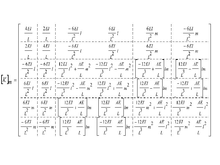
4. 6. 3 Frame element subjected to Shear Force/ Bending Moment/Axial Forces: Here ---------------- (4. 50) ---------------- (4. 40)
 and multiplying, structure stiffness matrix is")
and Substituting these values in equation (4. 53) and multiplying, structure stiffness matrix is given on the next page, is obtained.
- Slides: 21