4 2 Implied annotation The following rules shall


- Slides: 6
4. 2 Implied annotation The following rules shall govern the use and interpretation of implied annotation on engineering drawings. NOTE A dimension may be implied and not indicated on a drawing in the following circumstances, so long as there is no risk of misinterpretation. a) Where two features are aligned, there is no requirement to indicate a linear dimension of 0 or an angular dimension of 0°. b) Where two features are parallel to each other, there is no requirement to indicate an angular dimension of 0° or 180°. c) Where two features are at 90° to each other, there is no requirement to indicate an angular dimension of 90°. d) Where several features are equispaced around a pitch circle (see BS ISO 129 -1), there is no requirement to indicate an angular dimension, although it might be advisable to do so. Terms such as “equispaced”, “equally spaced”, etc. shall not be used. e) Where not otherwise indicated, holes are considered as through holes. If the features concerned have their locations and/or orientations controlled through the use of geometrical tolerances, then the implied dimensions shall be taken as Theoretically Exact Dimensions (TEDs; see BS EN ISO 1101). If the features concerned have their locations and/or orientations controlled through the use of +/− or limit tolerances, then the implied dimensions shall also be toleranced. In the absence of other indications, they shall be subject to a general tolerance, or else the TPS would remain incomplete. Tolerances shall never be implied, and shall always be indicated. Datums shall never be implied, and shall always be indicated
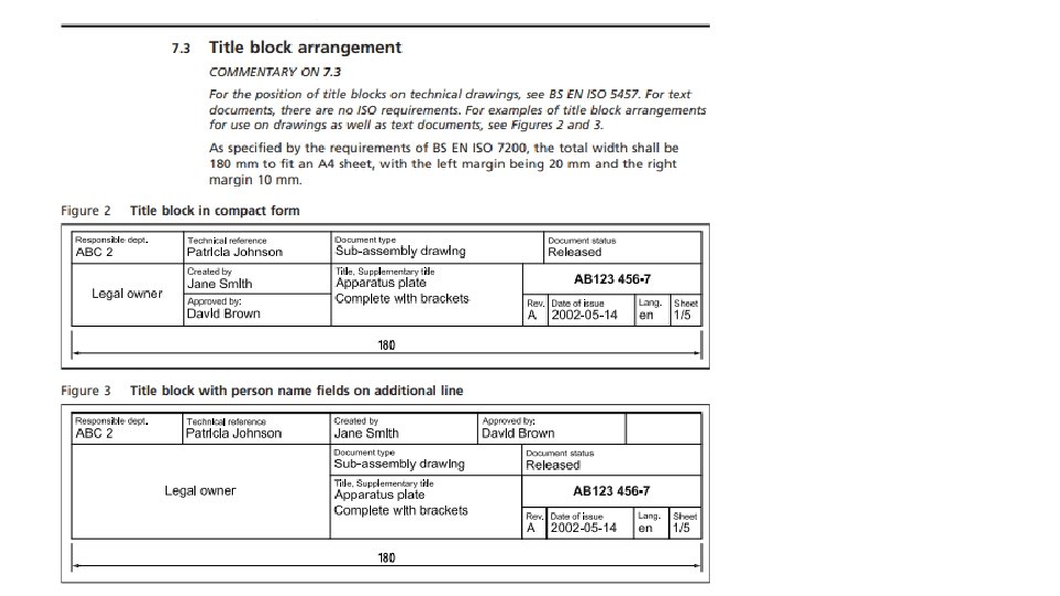
5. 2. 2 Format Drawing sheets and other documents shall be presented in one of the following formats. a) Landscape: intended to be viewed with the longest side of the sheet horizontal. b) b) Portrait: intended to be viewed with the longest side of the sheet vertical. *NOTE Contrary to BS EN ISO 5457, A 4 sheets may be used in landscape or portrait mode. 6. 2 Graphical features 6. 2. 1 Title block NOTE 1 For the dimensions and layout of title blocks, see BS EN ISO 7200. Sizes A 0 to A 3 shall be used in landscape orientation only (Figure 1) and the location of the title block shall be situated in the bottom right-hand corner of the drawing space. NOTE 2 A 4 sheets may be used in landscape or portrait orientation. For the size A 4, the title block shall be situated in the bottom righthand corner when used in landscape orientation, or the shorter (bottom) part of the drawing space when used in portrait.
6. 3. 2 Line width According to the requirements of BS EN ISO 128 -20, the width, d, of all types of line shall be one of the following depending on the type and size of drawing. 0, 13 mm, 0, 18 mm, 0, 25 mm, 0, 35 mm, 0, 7 mm, 1, 4 mm, 2 mm. NOTE 1 The widths of extra wide, wide and narrow lines are in the ratio 4: 2: 1. NOTE 2 For mechanical engineering drawings, four line types – continuous, dashed, chain (long-dashed dotted) and phantom (long-dashed double-dotted) – in two line thicknesses (typically 0, 35 mm and 0, 7 mm) are sufficient for most purposes. The line width of any one line shall be constant throughout the whole line.
6. 3. 2 Line width According to the requirements of BS EN ISO 12820, the width, d, of all types of line shall be one of the following depending on the type and size of drawing. 0, 13 mm, 0, 18 mm, 0, 25 mm, 0, 35 mm, 0, 7 mm, 1, 4 mm, 2 mm. NOTE 1 The widths of extra wide, wide and narrow lines are in the ratio 4: 2: 1. NOTE 2 For mechanical engineering drawings, four line types – continuous, dashed, chain (longdashed dotted) and phantom (long-dashed double-dotted) – in two line thicknesses (typically 0, 35 mm and 0, 7 mm) are sufficient for most purposes. The line width of any one line shall be constant throughout the whole line.
https: //www. letslearndt. com/uploa ds/4/2/8/6/42861013/bs 8888 -2011 -engineering_drawing. pdf