3 rd Generation DEMIWater Process Lewatit Fluidized Bed

3 rd Generation DEMI-Water Process Lewatit Fluidized Bed System
 Clarifier, Sand")
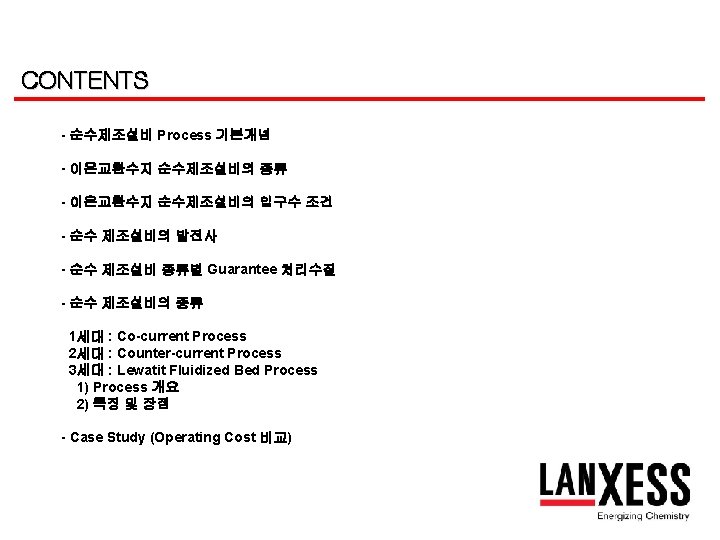
순수제조설비 Process 기본개념 Before Treatment 처리 SYSTEM After Treatment SS (Suspended Solids) Clarifier, Sand Filter Nothing A/C Filter Nothing Organics Ca Mg Na Nothing HCO 3 CO 2 SO 4 Cl NO 3 Si. O 2 H 2 O (H++OH-) Demi-Water Systems H+ OHH 2 O H 2 O (H++OH-)

이온교환수지 순수제조설비의 종류 Ion Exchange Resin Systems Softening Decarbonisation + Softening Polishing Ultra Pure Water 2 B 2 T MBP 2 B 3 T CPP MBP Anion Polisher 3 B 4 T Softening + MBP Cartridge Polisher Demi-Water Mixed Bed 4 B 5 T

Demi-Water Process Development History Flow 처리 수수 질 경제 성 폐수 발생 량 Generation 재생방식 1 st Generation (1940 ~ ) 병류재생 - Co-current X X X 2 nd Generation (1950 ~ ) 향류재생 - CCR ○ △ △ 3 rd Generation (1960 ~ ) 향류재생 -WS -Lift bed -Multistep -Rinse Bed 통수 재생 X : Bad, △ : Normal, ○ : Good, ◎ : Excellent ◎ ◎ ◎ 운전 용이 성 특허 최근 국내 보급 추이 ◎ - 거의 없음 : 특수한 경우 제외 X - 급격히 감소 추세임 ◎ Bayer 세계최초 Patent 대부분 Bayer process로 채 택, 보급추세
 Silica (ppb) 2")
Demi-Water Process별 Guarantee 처리수질 ⊙ Co-current system Process Conductivity (㎲/㎝ ) Silica (ppb) 2 B 2 T ~ 4 B 5 T 5. 0 100 MBD 0. 5 30 MBP 0. 1 20 CPP 0. 2 20 Process Conductivity (㎲/㎝ ) Silica (ppb) CCR (2 B 3 T) 2. 0 100 Conventional type Fluidized Bed (Lift bed, 2 B 3 T) 1. 0 20 Actual : 0. 2~0. 4㎲/㎝ Multistep (MBP 대용) 0. 1 20 Actual : 15 Mohm 이상 (17~18 Mohm) Remark ⊙ Counter-current system Remark

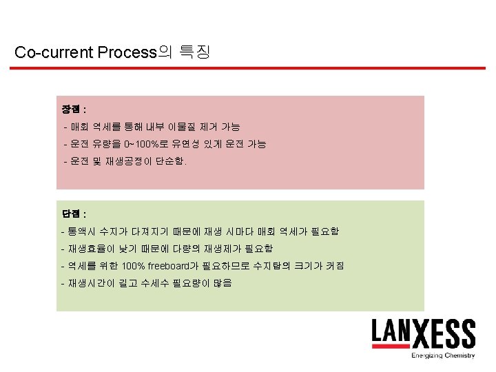
1세대 - Co-current Process Chemical Raw Water CO 2 Mono. Plus S 108 Air M 600 Monoplus M 800 Monoplus S 108

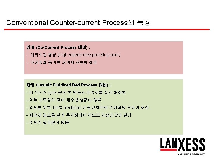
2세대 : Conventional Counter-current Process Raw Water CO 2 Monoplus Chemical Out Mono. Plus S 108 Chemical in Air Mono. Plus M 800 M 600 Monoplus S 108

3세대 : Lewatit Fluidized Bed Process Regenerant Treated water Inert Resin Fine Polishing layer Fixed Bed Floating Resin Raw water Throughput (Up flow) Waste Regeneration (Down flow)


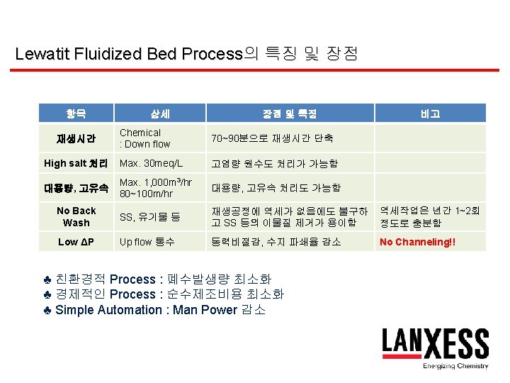
Lewatit Fluidized Bed Process의 특징 및 장점 항목 상세 장점 및 특징 비고 재생방식 Up flow 통수 Down flow 재생 기존의 CCR 재생방식 채택 : Polishing zone 사용 향류 재생방식의 장점 최대한 이용 비용절감 Chemical Water(원수, 폐수) 30 ~ 50% 절감 70 ~ 80% 절감 Low cost 처리수질 Conductivity Silica 0. 2 ~ 0. 3㎲/㎝ 20 ppb 이하 Good quality 설비구성 Internal 구조 No salan net No internal parts Very simple equipment (No Maintenance) 설치공간 (Space) Vessel 제작 Smaller space 역세 공간이 필요 없음. 재생공정 Regeneration Process 매우 복잡함 (지지수, 역세 등) Very simple Automation 복잡함 (지지수, 역세 등) Very simple 자동화

WS Process CO 2 Chemicals Mono. Plus S 108 Air Mono. Plus M 600 Monoplus M 800 Monoplus S 108 Raw water WS (Single Chamber)

WS Process의 특징 및 장점 - Downflow regeneration on a fixed bed 재생실패가 없음 - Lower chemical consumption 재생제 비용 절감 - High availability because of short regeneration time 재생시간 단축 - No channelling, low pressure drops 수지수명 증가 - Reduced waste water 폐수발생량 감소 - Improved water quality 처리수질 향상 - Reduced investment 적은 공간에 설치 가능 - Reduced operating costs 순수제조비용 감소 - Back Wash 년 1~2회 실시로 충분

VWS Process CO 2 Mono. Plus S 108 M 500 Mono. Plus M 800 Air Mono. Plus S 108 CNP 80 WS Mono. Plus MP 64 Demi Water Out Raw Water In VWS (Double Chamber)

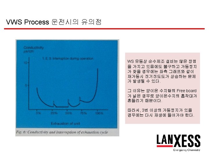
VWS Process의 특징 및 장점 - Like Fluidized bed system bed 유동상 순수제조 설비의 장점을 가지고 있음. - Higher regeneration efficiency 재생효율이 획기적으로 증가함. (Strong Anion의 Excess 재생제로 Weak Anion 재생) - Using of weak and strong dissociated resins in one filter column 수지탑 중간에 다공판이 있어 강, 약 두 종류의 수지를 사용가능. Low Silica leakage : 20 ppb 이하 (SBA, 2형은 100 ppb 이하) 년간 성능저하율 : 5~10%/year (SBA, 2형은 15~20%/year)

Lift bed Process CO 2 Chemical In Mono. Plus S 108 M 500 Mono. Plus M 800 Mono. Plus Air S 108 Mono. Plus S 108 Raw water In MP 64 Demi Water Out Rinse out Lift Bed (Double Chamber) VWS (Double Chamber)

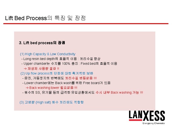
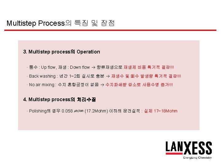
Lift Bed Process의 특징 및 장점 1. Lift bed process의 개요 · Lift bed Process는 Fluidized Bed 의 원리를 적용한 가장 Upgrade된 Process 임 · Fluidized Bed의 모든 장점 외에도 Back Washing이 수지탑 내에서 실행 되어 매우 간편 2. Lift bed process의 구성 · 중간에 1~2 plate로 나누어 상하 2~3개의 Chamber로 구성 · 각 Chamber는 Lift pipe로 연결되어 수지 이동 가능


Multistep Process co 2 Demi Water Mono. Plus S 108 M+ S 108 M 500 Airr M+ M 500 Mono. Plus S 108 MP 64 M+ S 108 Raw water Lift Bed (Double Chamber) VWS (Double Chamber) Multistep (Triple Chamber)
으로부터")
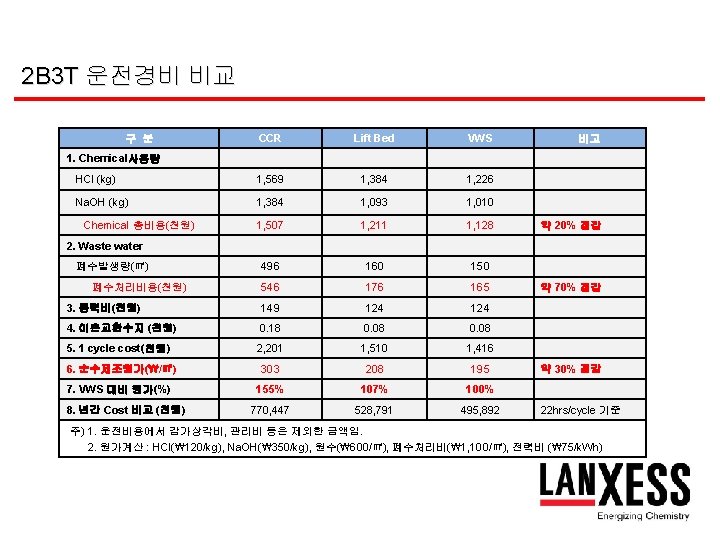
Case Study / Operating Cost 비교 1. 개요 이온교환수지를 이용한 순수제조설비는 제 1세대 방식(Co-current)으로부터 제 2세대 방식 (CCR), 제 3세대 방식(Fluidized bed, 유동상)으로 발전되어왔으며, 각 Process 별 순수제조 설비의 운전경비를 비교하여 경제성을 비교 검토하고자 한다. 2. Case Study (1) Plant : K사 (열병합발전소, 군산) (2) Flow rate : 330 m 3/hr X 22 hrs (Net 7, 200 m 3/cycle) (3) Raw water - Conductivity - Turbidity - TDS - Total Cation - Total Anion - Silica : 475 u. S/cm : 1~3 mg/L as Kaolin : 257 mg/L : 190. 55 mg/L as Ca. CO 3 : 4. 0 mg/L as Ca. CO 3

2 B 3 T 폐수발생량 비교 구 분 CCR Lift Bed VWS Remark Net (m 3) Waste water (m 3) 7, 200 498 7, 200 150 7, 200 160 CCR 대비 폐수 발생 량이 약 30% 수준까 지 감소함 Gross Total (m 3) 7, 698 7, 350 7, 360 폐수발생량 (%) 6. 4% 2. 08% 2. 17% Gross 생산량 대비 년간 통액량 (m 3) (350 cycle/year) 2, 694, 300 2, 572, 500 2, 576, 000 Net 25, 200, 000 m 3 순수생산 기준
 330 m")
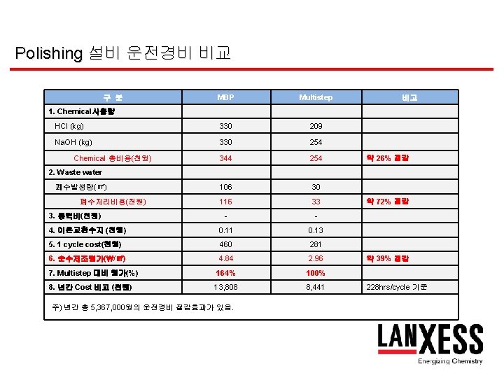
Polishing 설비 폐수발생량 비교 구 분 MBP Multistep Remark Net (m 3) 330 m 3/hr X 288 hrs = 95, 040 Waste water (m 3) 106 30 Gross Total (m 3) 95, 146 95, 070 폐수발생량 (%) 0. 11% 0. 03% Gross 생산량 대비 년간 통액량 (m 3) (30 cycles/year) 2, 854, 380 2, 852, 100 Net 2, 851, 200 m 3 순수생산 기준 12 day/cycle 재생주기 1 cycle 기준
- Slides: 34