3 FLOOR ELEVATOR Image 4 elevator shaft ENG


- Slides: 12
3 FLOOR ELEVATOR Image 4: elevator shaft ENG 311 -PLC Jo Court Jack
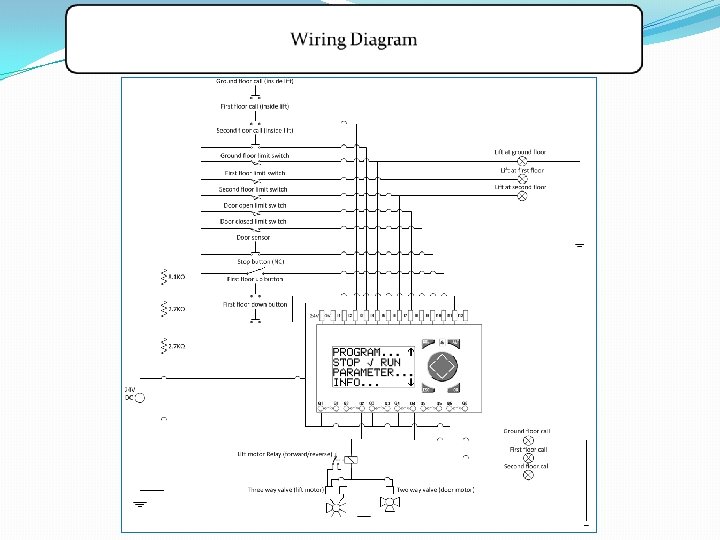
Content Project Outline Design base Flow chart Code design Wiring diagram Problems faced Improvements Image 1: Elevator
Project Outline v Program an Moeller easy soft 719 -DC-RC to control a 3 floor lift. v Before installing a PLC unit into an actual lift it is important to test/simulate the ladder logic program on a smaller scale. v Using pneumatics, actuators, switches, relays and lights. Image 2: Moeller
DESIGN BASE v Program designed around a pneumatic vacuum elevator, different pressures to control the movements of the cabin. v 3 floor for a more complex program design, floor call logic. First floor has up/down call which will only be picked up on the correct path, will override path if no other floor called. Image 3: Pneumatic vacuum elevator
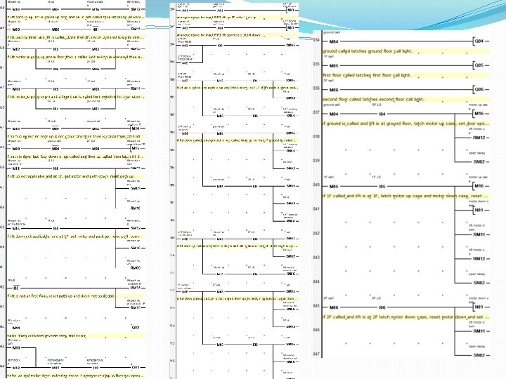
Flow Chart
Code Design v Emergency stop-failsafe v Motor up/down functions v Analogue inputs-use of a voltage divider v Use of Extra Memories bits to extend lines-more conditions v Pushbutton displays v Wiring floor lights straight to limit switches –not enough outputs v Notepad register v Monitor screen on the PLC unit to display lift movement
Code Design
Problems Faced v 3 way valve actuator to control the level pneumatic- 3 different stopping locations(ground, first and second) v Not enough outputs on the PLC –connected floor lights to the limit switches for each floor v N/O limit switches v Extend the top of the ram (block) so the ram had time to stop on the correct floor before releasing the limit switch v Door open control
Improvements v To read floor call demands while lift is between limit switches v Emergency stop should release pressure on doors so they can be opened manually v Emergency stop should also have a connecting phone line to emergency services v Key register for debugging different sequences v Markers for previous floors, mid movement the floor can be called
References Image 1: elevator http: //www. thangmaymitsubishijapan. com/san-pham/thang-may-tai-khach-2. html Image 2: Moeller http: //controlparts. com/klockner. moeller/p/easy 719 -dc-rc. htm Image 3: Pneumatic vacuum elevator http: //www. daytonaelevator. com/Pneumatic%20 Vacuum%20 Elevator%20 Main%20 Page. htm) Image 4: elevator shaft http: //www. fastcompany. com/3020867/reverse-engineered/how-an-elevator-will-change-the-skyline