3 D Homogeneous Transformations Coordinate transformation translationrotation 3

")

")


 Ø joints (prismatic and revolute)")


 v Z 1 (out of board) v Z")


 =")


![Matlab Toolbox Link([alpha a theta d sig]) Ø link 1 = link([-pi/2 0 0])](https://slidetodoc.com/presentation_image_h2/792cb79792961624d9451b248de449d5/image-51.jpg "Matlab Toolbox Link([alpha a theta d sig]) Ø link 1 = link([-pi/2 0 0])")
 Øplot(Ant, [-pi/2 Ødrivebot(Ant) pi/3")

![Check 3 -Link Robot: 1=270, 2= 3=0 T=fkine(Ant, [-pi/2 0 0])](https://slidetodoc.com/presentation_image_h2/792cb79792961624d9451b248de449d5/image-54.jpg "Check 3 -Link Robot: 1=270, 2= 3=0 T=fkine(Ant, [-pi/2 0 0])")


- Slides: 57
3 -D Homogeneous Transformations Ø Coordinate transformation (translation+rotation)
3 -D Homogeneous Transformations Ø Homogeneous vector Ø Homogeneous transformation matrix From frame 0 to frame 1
3 -D Homogeneous Transformations Ø Coordinate transformation (translation+rotation)
3 -D Homogeneous Transformations
3 -D Homogeneous Transformations Ø Composition of coordinate transformations
3 -D Homogeneous Transformations Ø add another row and column to handle the 3 rd (Z) dimension 82
3 -D Homogeneous Transformations Ø rotations about X and Y axes, Show direction cosines! 83
3 -D Homogeneous Transformations Ø translate along X axis by a, along Y by b, and along Z axis by d, 84
Direct Kinematics Ø Manipulator structure: Ø links (rigid body) Ø joints (prismatic and revolute) Ø mobility Ø joint variables(angle or displacement) Ø kinematic chain Ø base Ø End-effector
Aim of Direct Kinematics Compute the position and orientation of the end effector as a function of the joint variables
Definition of End Effector Frame Ø approaching direction Ø sliding direction X Ø normal direction Y Z
Direct Kinematics Ø The direct kinematics function is expressed by the homogeneous transformation matrix
Open Chain
Open Chain Ø Computation of direct kinematics function is recursive and systematic
What is the configuration of the object in Fb?
85
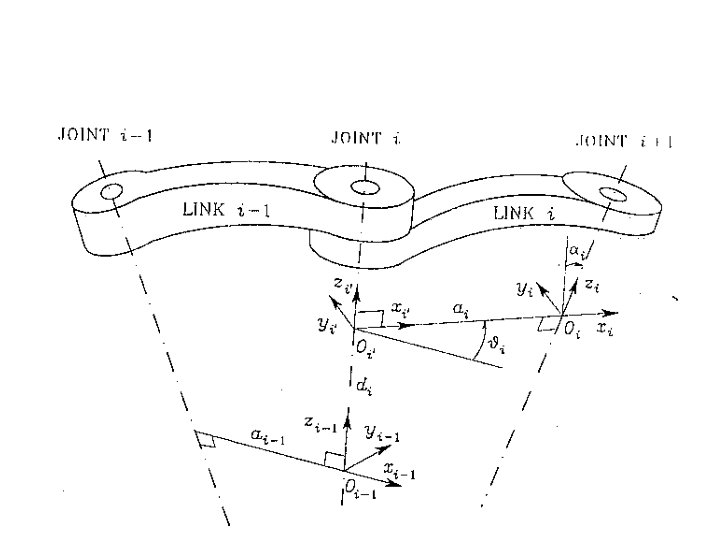
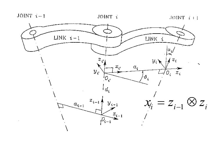
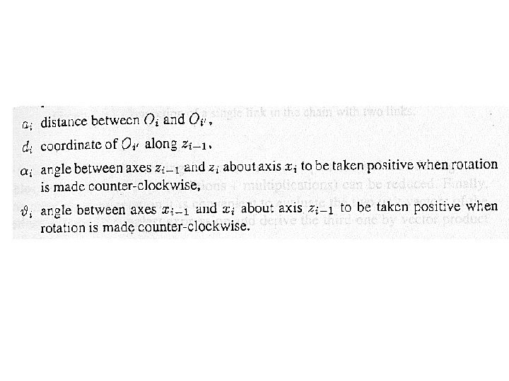
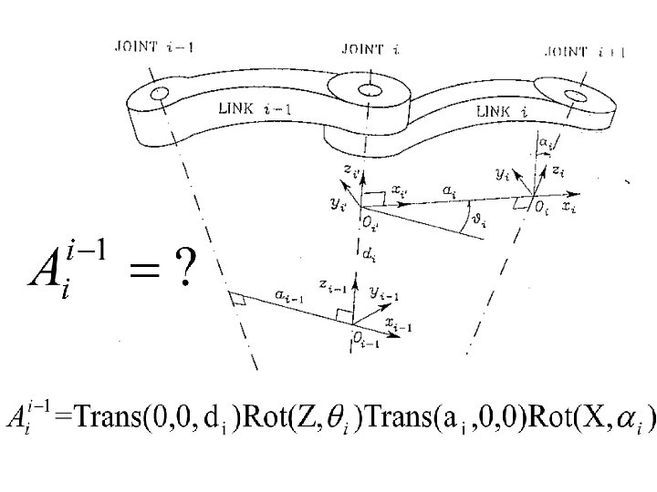
Denavit-Hartenberg Convention Ø Note that only one of the 4 D-H parameters is a joint variable, either • • Ø qn - for a revolute joint (usually driven by a motor), or dn - for a prismatic joint All of the other parameters of the D-H transformation matrix are associated with the link (and are constants!)
Denavit-Hartenberg Convention Ø D-H transformation is a set of 4 homogeneous transformation matrices in the given order (based on a “left-to-right” interpretation!) • translate along Zn-1 axis a distance dn • rotate about the Zn-1 axis by an angle qn • translate along rotated Xn axis by an • rotate about the new Xn axis by angle an 86
Denavit-Hartenberg Convention Ø recall that successive translations can be combined, Joint type
89
v Z 2 (out of board) v Z 1 (out of board) v Z 0 (out of board) 90
X 2 v Z 2 X 1 v Z 0 X 0 91
Y 2 Y 0 X 2 v Y 1 X 1 v v X 0 92
93
Y 0 R y 0 What are the D-H parameters? y 2 v x 2 a 2 Y 1 2 X 1 v a 1 1 0 v 0 x 0 X 0 Figure 2. 13: Two-Link Planar Robot
D-H Example #1 • Table 2. 1: D-H parameters for Two-Link Robot 95
96
D-H Example #1 97
D-H Example #1 Ø after matrix multiplication and trig identity substitution, 98
Y 0 y 2 v x 2 a 2 Y 1 2 v a 1 X 1 The textbook is wrong 1 0 v 0 Two-Link Planar Robot X 0
Class Problem - RPR Planar Robot Y 0 1 st Joint: Revolute Tool Center Point 3 rd Joint: Revolute 90 deg 2 nd Joint: Prismatic X 0
D-H Example #2 ØA three-link revolute robot is shown in Figure 2. 14 Ø Similar in features to the PUMA type robot, it has • • “waist” joint left “shoulder” joint “elbow” joint “wrist” at the end of the “forearm” 99
Shoulder “Wrist” Waist Elbow Figure 2. 14: Three-Link Revolute Robot
D-H Example #2 Ø assign Z 0 axis along the “waist” joint Ø assign Z 1 axis along the “shoulder” joint Ø assign Z 2 axis along the “elbow” joint Ø assign Z 3 axis where the first “wrist” joint is located 101
Z 0 Z 1 a 2 Z 3 a 3 Z 2 Figure 2. 15: Assignment of Z Axes
D-H Example #2 Ø X 0 axis assignment is completely arbitrary (although it is usually assigned to intersect X 1) Ø assign X 1 along the common normal to Z 1 and Z 0 Ø assign X 2 along the common normal to Z 2 and Z 1 Ø assign X 3 along the common normal to Z 3 and Z 2 103
X 3 Z 0 Z 1 X 0 Z 3 d 2 Z 2 X 1 X 2 Figure 2. 16: Assignment of X Axes 104
D-H Example #2 Ø What are the D-H parameters for Three. Link Revolute Robot? 105
D-H Example #2 • substituting parameters into the D-H matrix, note that cos(270) = 0, sin(270) = -1 106
D-H Example #2 107
D-H Example #2 • perform successive substitutions as shown below, • note definition of overall transformation 108
D-H Example #2 109
Matlab Toolbox Link([alpha a theta d sig]) Ø link 1 = link([-pi/2 0 0]) Ø link 1. qlim =[-pi pi] Ø link 2 = link([0 2 0 Ø link 2. qlim = [-pi pi] Ø link 3 = link([0 2 Ø link 3. qlim = [-pi pi] Ø 0 2 0]) 0 0]) 110
Matlab Toolbox ØAnt = robot({link 1 link 2 link 3}) Øplot(Ant, [-pi/2 Ødrivebot(Ant) pi/3 -pi/2])
Check 3 -Link Robot: 1=270, 2= 3=0 X 3 Z 0 Z 1 X 0 Z 3 d 2 Z 2 X 1 X 2
Check 3 -Link Robot: 1=270, 2= 3=0 T=fkine(Ant, [-pi/2 0 0])
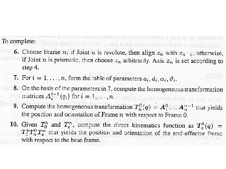
D-H Matrices for 6 Link Robots Ø overall transformations get very messy! Ø many robot kinematic transformations can be separated at the wrist to simplify 120
Class Problem - Spherical Wrist 121
Page 58