
3 D Displays Overview Revision 1 3 Copyright

- Slides: 55
3 D Displays Overview Revision 1. 3 Copyright 2006 Zachary Wartell University of North Carolina Charlotte © Dr. Zachary Wartell 3/23/2005 1
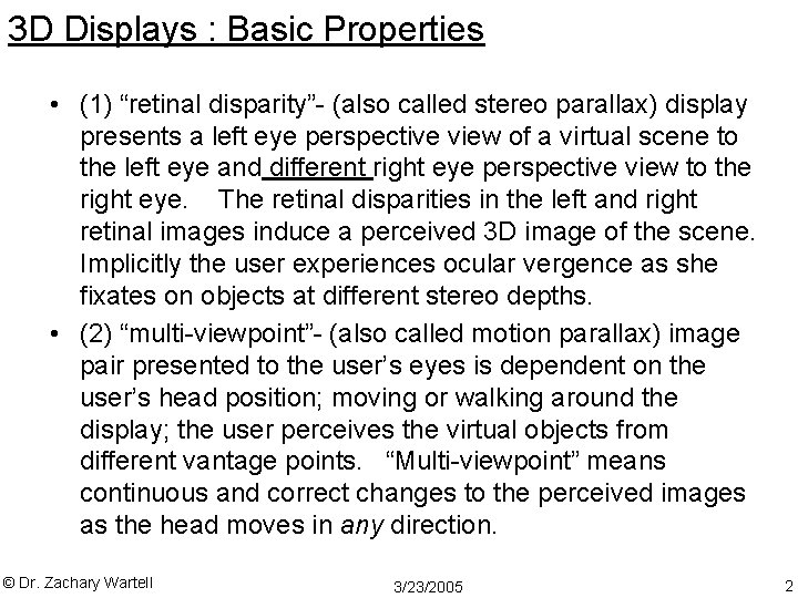
3 D Displays : Basic Properties • (1) “retinal disparity”- (also called stereo parallax) display presents a left eye perspective view of a virtual scene to the left eye and different right eye perspective view to the right eye. The retinal disparities in the left and right retinal images induce a perceived 3 D image of the scene. Implicitly the user experiences ocular vergence as she fixates on objects at different stereo depths. • (2) “multi-viewpoint”- (also called motion parallax) image pair presented to the user’s eyes is dependent on the user’s head position; moving or walking around the display; the user perceives the virtual objects from different vantage points. “Multi-viewpoint” means continuous and correct changes to the perceived images as the head moves in any direction. © Dr. Zachary Wartell 3/23/2005 2
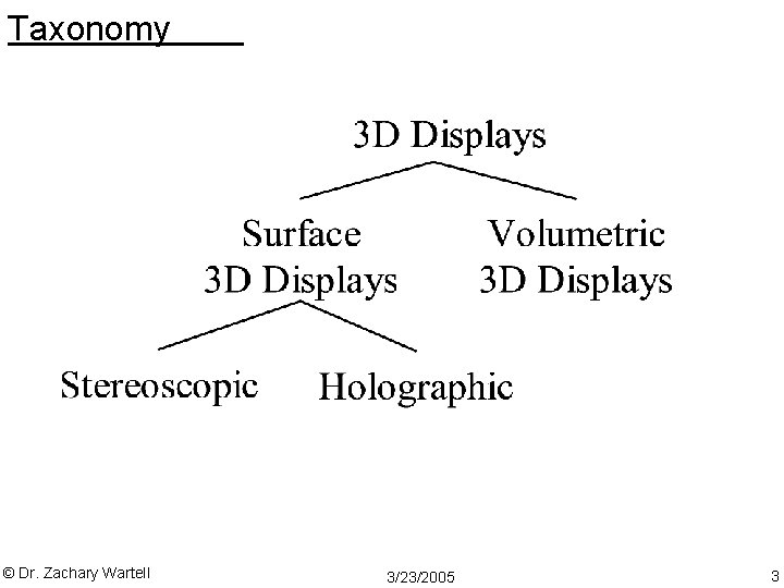
Taxonomy © Dr. Zachary Wartell 3/23/2005 3
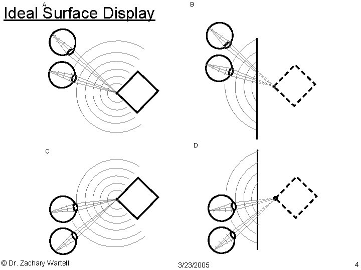
A Ideal Surface Display C © Dr. Zachary Wartell B D 3/23/2005 4
Physical world creates natural blur © Dr. Zachary Wartell 3/23/2005 5
Ideal Surface Display creates natural blur © Dr. Zachary Wartell 3/23/2005 6
Stereoscopic Surface Display • cannot create the wavefronts of the synthetic 3 D • multi-viewpoint property: a stereoscopic display must : – determine the user’s head position – render a left and right eye image specifically computed for that head position; – channel each of the two images to the appropriate eye. (while at a given moment a full holographic display outputs an image for every possible eye position, a typical stereoscopic display outputs an image for only the two current eye positions). © Dr. Zachary Wartell 3/23/2005 7
Stereoscopic Surface Display Wavefronts © Dr. Zachary Wartell 3/23/2005 8
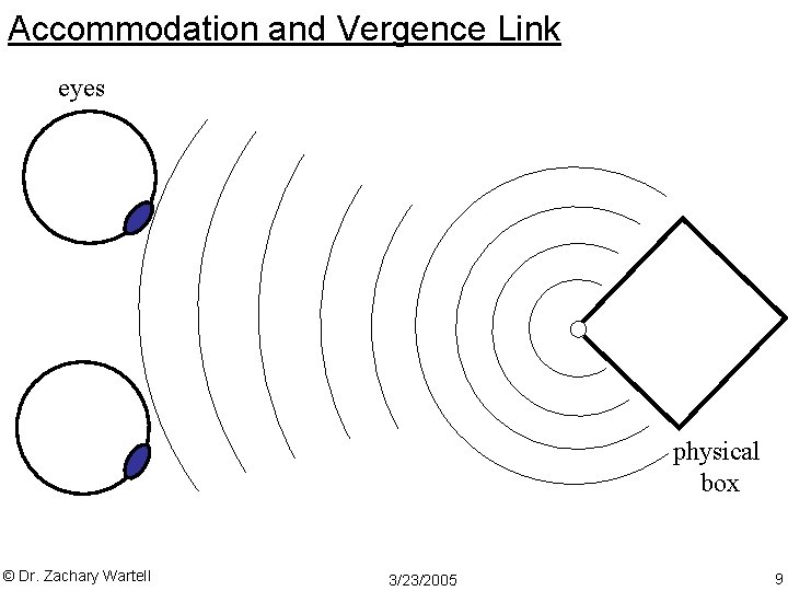
Accommodation and Vergence Link eyes physical box © Dr. Zachary Wartell 3/23/2005 9
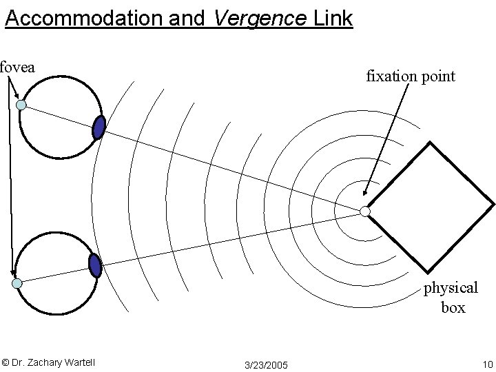
Accommodation and Vergence Link fovea fixation point physical box © Dr. Zachary Wartell 3/23/2005 10
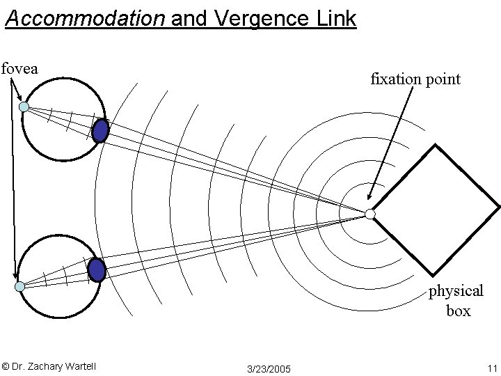
Accommodation and Vergence Link fovea fixation point physical box © Dr. Zachary Wartell 3/23/2005 11
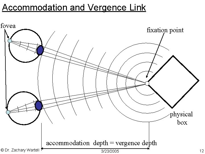
Accommodation and Vergence Link fovea fixation point physical box accommodation depth = vergence depth © Dr. Zachary Wartell 3/23/2005 12
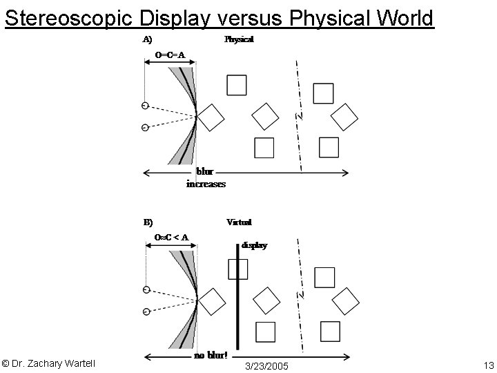
Stereoscopic Display versus Physical World © Dr. Zachary Wartell 3/23/2005 13
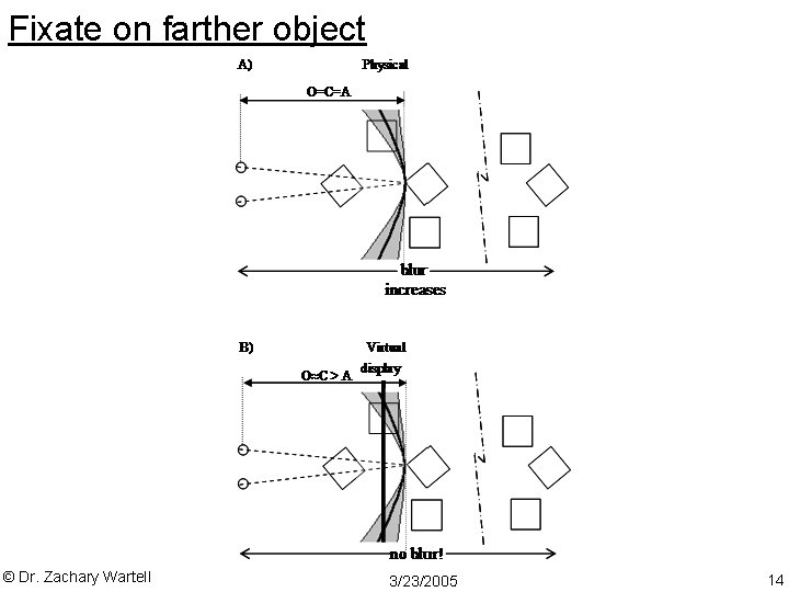
Fixate on farther object © Dr. Zachary Wartell 3/23/2005 14
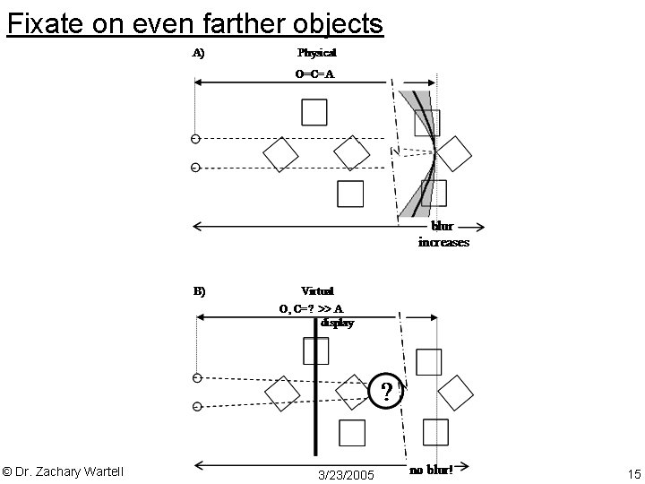
Fixate on even farther objects © Dr. Zachary Wartell 3/23/2005 15
Fusion Metrics -screen parallax, HVA, vergence difference © Dr. Zachary Wartell 3/23/2005 16
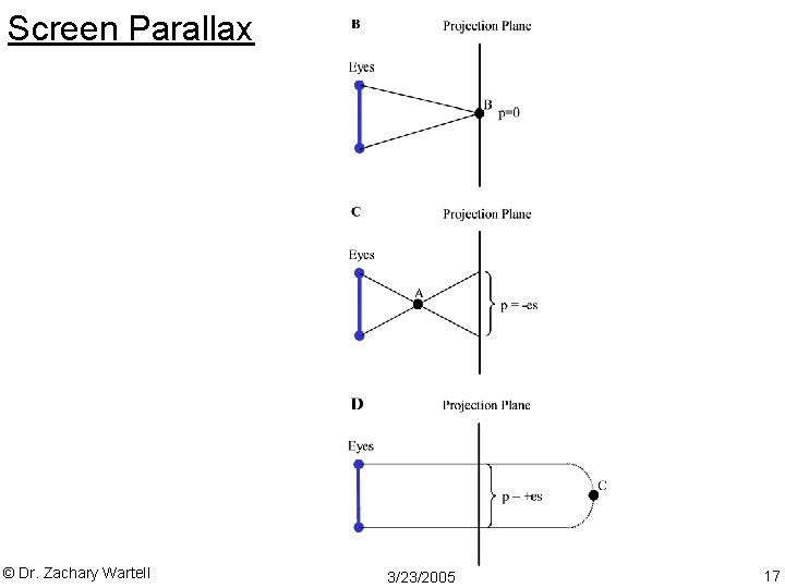
Screen Parallax © Dr. Zachary Wartell 3/23/2005 17
Vergence Difference ( - ) © Dr. Zachary Wartell 3/23/2005 18
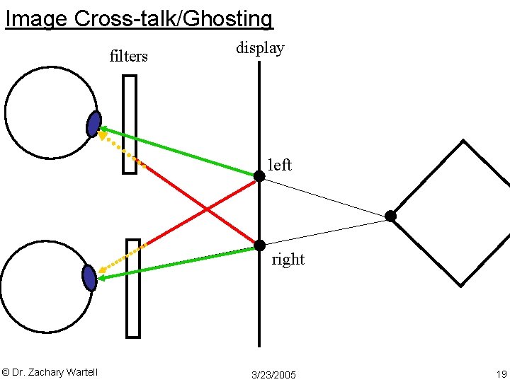
Image Cross-talk/Ghosting filters display left right © Dr. Zachary Wartell 3/23/2005 19
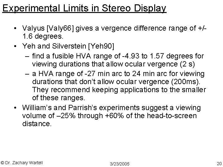
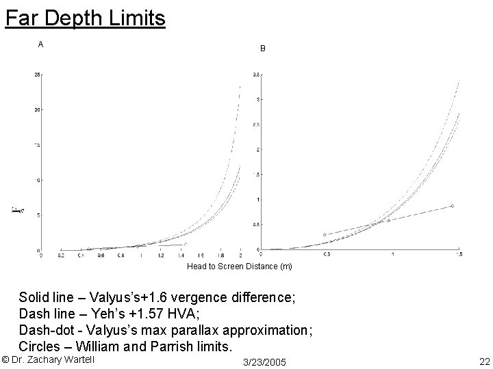
Experimental Limits in Stereo Display • Valyus [Valy 66] gives a vergence difference range of +/1. 6 degrees. • Yeh and Silverstein [Yeh 90] – find a fusible HVA range of -4. 93 to 1. 57 degrees for viewing durations that allow ocular vergence (2 s) – a HVA range of -27 min arc to 24 min arc for viewing durations that don’t allow ocular vergence (200 ms). They recommend keeping applications to the smaller of these ranges. • William’s and Parrish’s experiments suggest a viewing volume of – 25% through +60% of the head-to-screen distance. © Dr. Zachary Wartell 3/23/2005 20
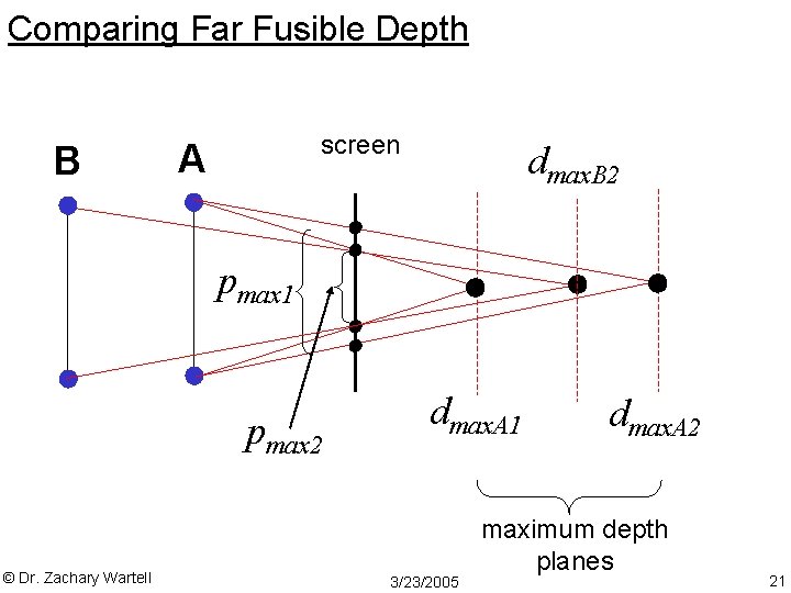
Comparing Far Fusible Depth B screen A dmax. B 2 pmax 1 pmax 2 © Dr. Zachary Wartell dmax. A 1 3/23/2005 dmax. A 2 maximum depth planes 21
Far Depth Limits A B Head to Screen Distance (m) Solid line – Valyus’s+1. 6 vergence difference; Dash line – Yeh’s +1. 57 HVA; Dash-dot - Valyus’s max parallax approximation; Circles – William and Parrish limits. © Dr. Zachary Wartell 3/23/2005 22
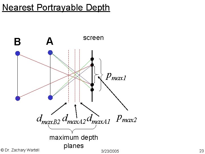
Nearest Portrayable Depth A B screen pmax 1 dmax. B 2 dmax. A 1 pmax 2 © Dr. Zachary Wartell maximum depth planes 3/23/2005 23
Limitations of Fusibility Limits • varies with display technology • varies with contrast of given image • scenes have arbitrary distribution of depth – experiments usually use single stimuli • individual differences, etc. © Dr. Zachary Wartell 3/23/2005 24
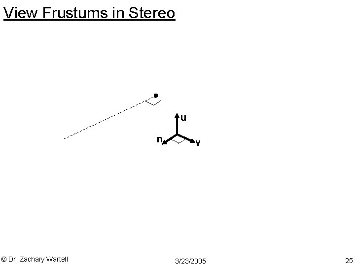
View Frustums in Stereo u n © Dr. Zachary Wartell v 3/23/2005 25
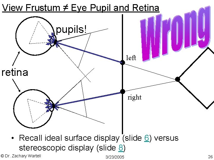
View Frustum ≠ Eye Pupil and Retina pupils! left retina right • Recall ideal surface display (slide 6) versus stereoscopic display (slide 8) © Dr. Zachary Wartell 3/23/2005 26
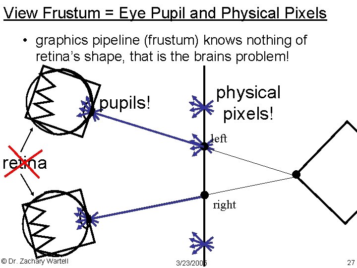
View Frustum = Eye Pupil and Physical Pixels • graphics pipeline (frustum) knows nothing of retina’s shape, that is the brains problem! physical pixels! pupils! left retina right © Dr. Zachary Wartell 3/23/2005 27
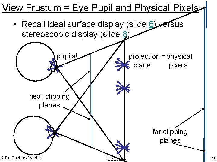
View Frustum = Eye Pupil and Physical Pixels • Recall ideal surface display (slide 6) versus stereoscopic display (slide 8) pupils! projection =physical plane pixels near clipping planes far clipping planes © Dr. Zachary Wartell 3/23/2005 28
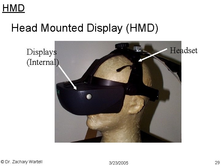
HMD Head Mounted Display (HMD) Headset Displays (Internal) © Dr. Zachary Wartell 3/23/2005 29
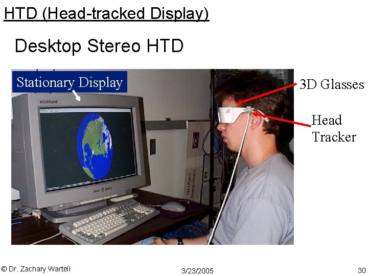
HTD (Head-tracked Display) Desktop Stereo HTD Stationary Display 3 D Glasses Head Tracker © Dr. Zachary Wartell 3/23/2005 30
View Coordinate Hierarchy (Simplified) © Dr. Zachary Wartell 3/23/2005 31
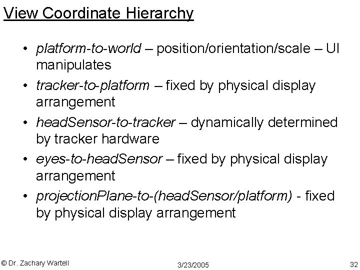
View Coordinate Hierarchy • platform-to-world – position/orientation/scale – UI manipulates • tracker-to-platform – fixed by physical display arrangement • head. Sensor-to-tracker – dynamically determined by tracker hardware • eyes-to-head. Sensor – fixed by physical display arrangement • projection. Plane-to-(head. Sensor/platform) - fixed by physical display arrangement © Dr. Zachary Wartell 3/23/2005 32
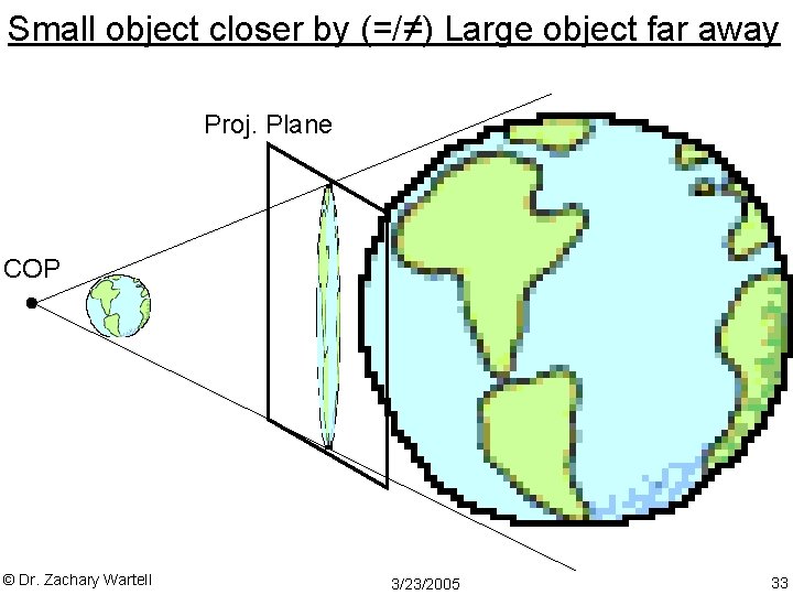
Small object closer by (=/≠) Large object far away Proj. Plane COP © Dr. Zachary Wartell 3/23/2005 33
Platform Scale DOF © Dr. Zachary Wartell 3/23/2005 34
Four Eye Separations © Dr. Zachary Wartell 3/23/2005 35
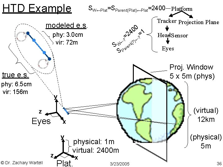
HTD Example SW←Plat=SParent(Plat)←Plat=2400 Platform modeled e. s. phy: 3. 0 cm vir: 72 m 00 1 4 =2 ? = ← ? )← S W are SP (? nt Tracker Projection Plane Head- Sensor Eyes Proj. Window 5 x 5 m (phys) true e. s. phy: 6. 5 cm vir: 156 m y (virtual) 12 km z Eyes x y z © Dr. Zachary Wartell physical: 1 m virtual: 2400 m Plat. (physical) 5 m x 3/23/2005 36
Goals for 3 D Display • generating fusible stereoscopic imagery • generating accurate stereoscopic imagery • maximizing the added value of stereoscopic depth images • minimizing frame cancellation • bringing manipulated stereoscopic imagery within arms’ reach to improve direct manipulation © Dr. Zachary Wartell 3/23/2005 37
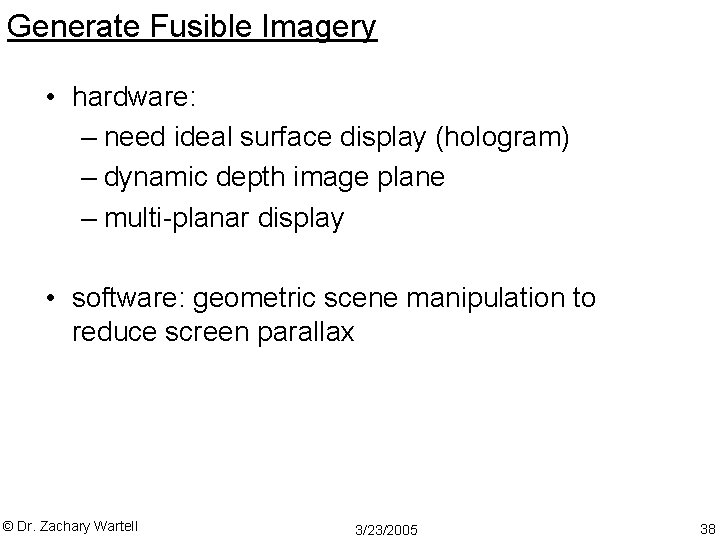
Generate Fusible Imagery • hardware: – need ideal surface display (hologram) – dynamic depth image plane – multi-planar display • software: geometric scene manipulation to reduce screen parallax © Dr. Zachary Wartell 3/23/2005 38
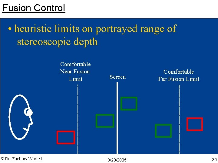
Fusion Control • heuristic limits on portrayed range of stereoscopic depth Comfortable Near Fusion Limit © Dr. Zachary Wartell Screen 3/23/2005 Comfortable Far Fusion Limit 39
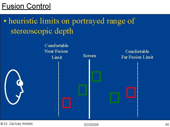
Fusion Control • heuristic limits on portrayed range of stereoscopic depth Comfortable Near Fusion Limit © Dr. Zachary Wartell Screen 3/23/2005 Comfortable Far Fusion Limit 40
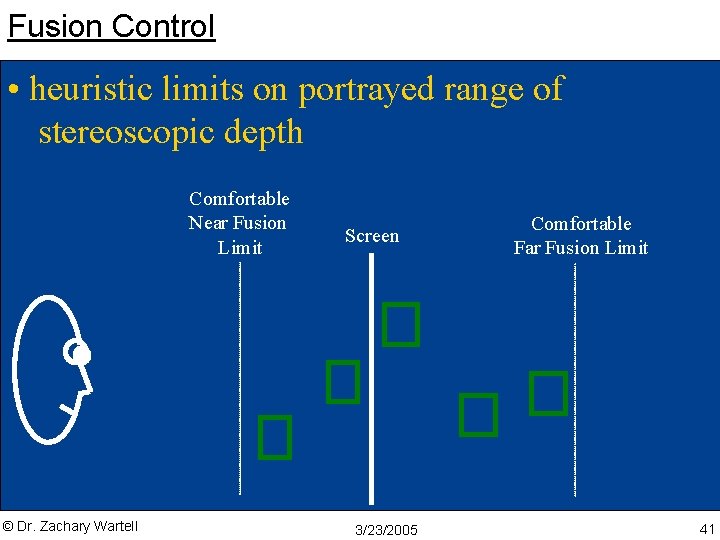
Fusion Control • heuristic limits on portrayed range of stereoscopic depth Comfortable Near Fusion Limit © Dr. Zachary Wartell Screen 3/23/2005 Comfortable Far Fusion Limit 41
Frame cancellation/window violation © Dr. Zachary Wartell 3/23/2005 42
Frame cancellation/window violation © Dr. Zachary Wartell 3/23/2005 43
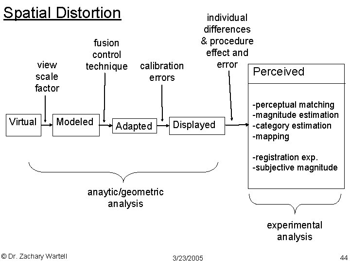
Spatial Distortion view scale factor Virtual fusion control technique Modeled calibration errors Adapted individual differences & procedure effect and error Displayed Perceived -perceptual matching -magnitude estimation -category estimation -mapping -registration exp. -subjective magnitude anaytic/geometric analysis experimental analysis © Dr. Zachary Wartell 3/23/2005 44
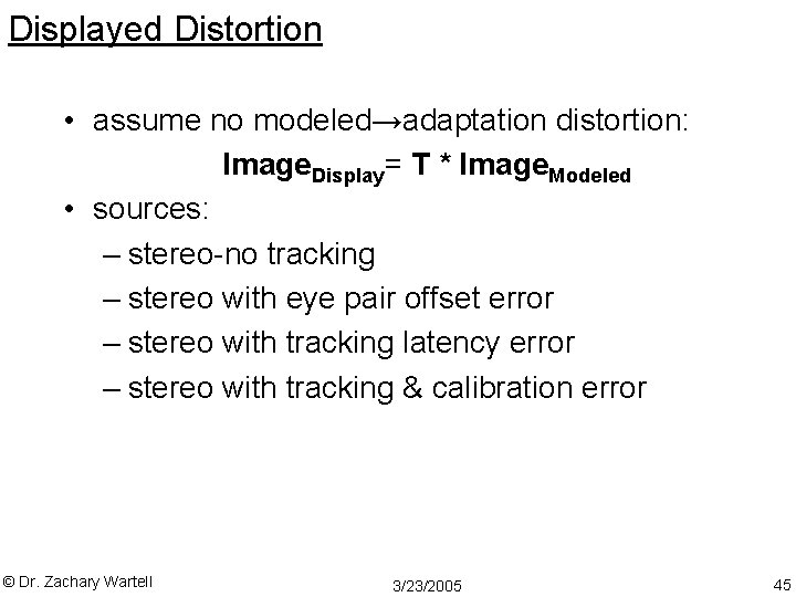
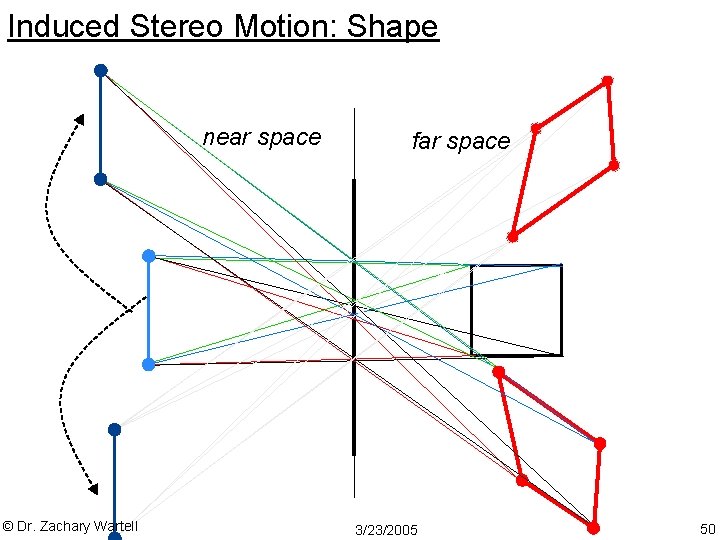
Displayed Distortion • assume no modeled→adaptation distortion: Image. Display= T * Image. Modeled • sources: – stereo-no tracking – stereo with eye pair offset error – stereo with tracking latency error – stereo with tracking & calibration error © Dr. Zachary Wartell 3/23/2005 45
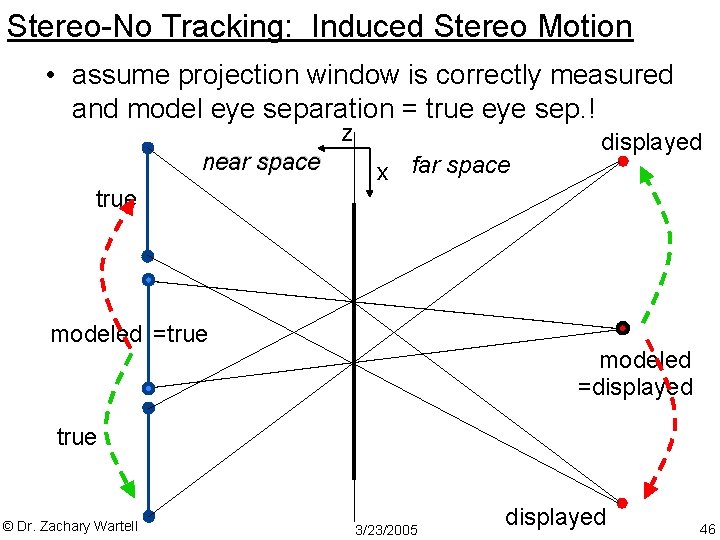
Stereo-No Tracking: Induced Stereo Motion • assume projection window is correctly measured and model eye separation = true eye sep. ! z near space true x far space modeled =true displayed modeled =displayed true © Dr. Zachary Wartell 3/23/2005 displayed 46
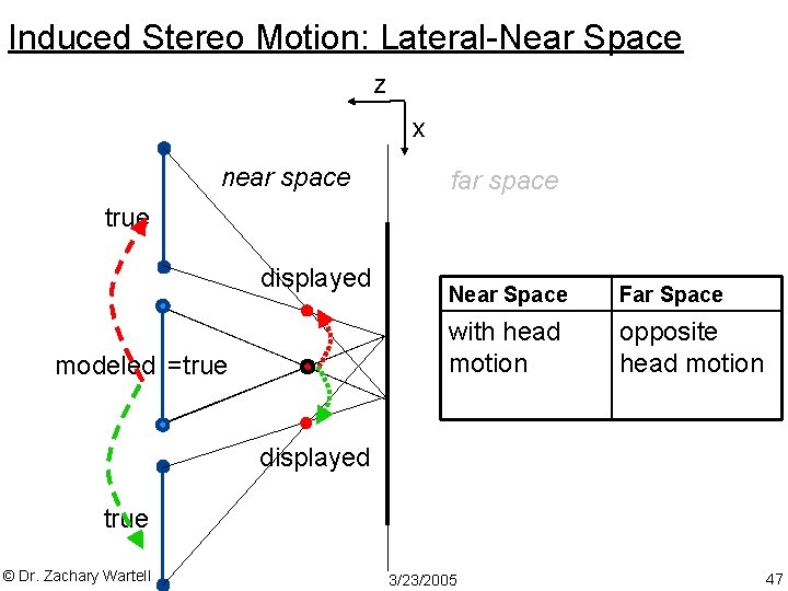
Induced Stereo Motion: Lateral-Near Space z x near space far space true displayed modeled =true Near Space Far Space with head motion opposite head motion displayed true © Dr. Zachary Wartell 3/23/2005 47
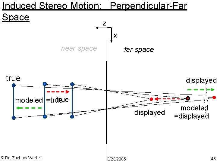
Induced Stereo Motion: Perpendicular-Far Space z x near space far space true displayed true modeled =true displayed © Dr. Zachary Wartell 3/23/2005 modeled =displayed 48
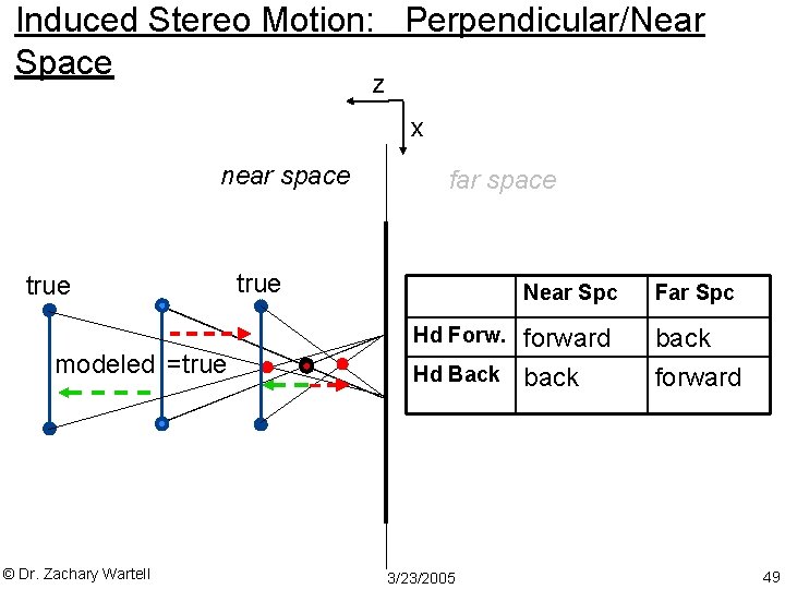
Induced Stereo Motion: Perpendicular/Near Space z x near space true far space true Near Spc Hd Forw. modeled =true © Dr. Zachary Wartell forward Hd Back back 3/23/2005 Far Spc back forward 49
Induced Stereo Motion: Shape near space © Dr. Zachary Wartell far space 3/23/2005 50
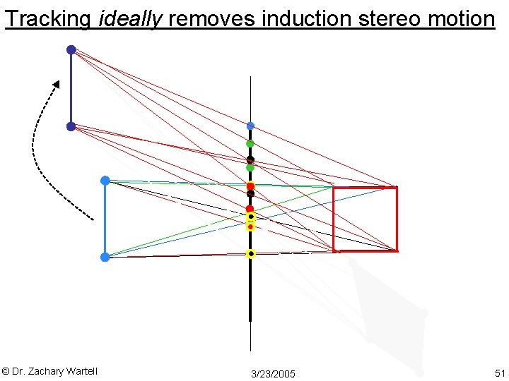
Tracking ideally removes induction stereo motion © Dr. Zachary Wartell 3/23/2005 51
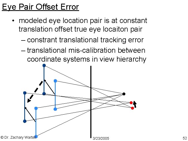
Eye Pair Offset Error • modeled eye location pair is at constant translation offset true eye locaiton pair – constrant translational tracking error – translational mis-calibration between coordinate systems in view hierarchy © Dr. Zachary Wartell 3/23/2005 52
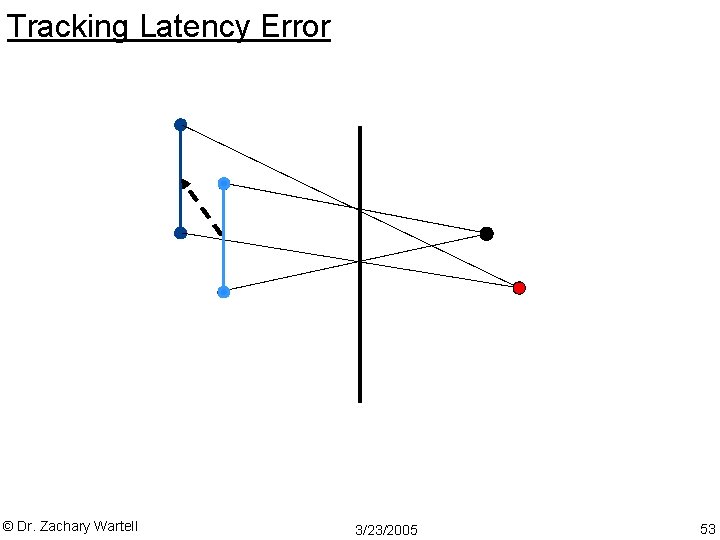
Tracking Latency Error © Dr. Zachary Wartell 3/23/2005 53
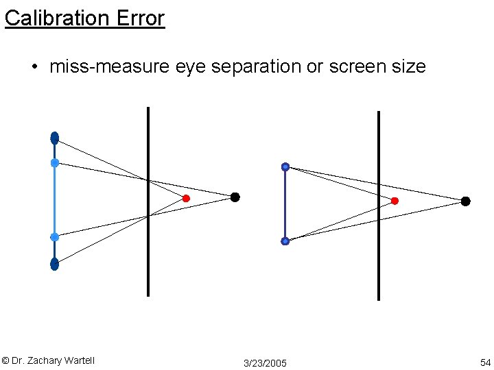
Calibration Error • miss-measure eye separation or screen size © Dr. Zachary Wartell 3/23/2005 54
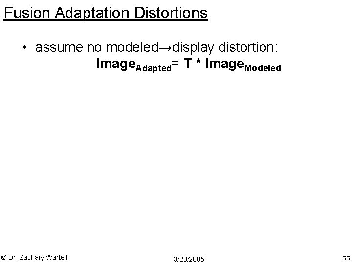
Fusion Adaptation Distortions • assume no modeled→display distortion: Image. Adapted= T * Image. Modeled © Dr. Zachary Wartell 3/23/2005 55