3 Balancing Machine Balancing Shop Balancing Low Speed

3 Balancing Machine Balancing Shop Balancing Low Speed Balancing Machine High Speed Balancing Machine Soft Mount Type Hard Mount Type Field Balancing

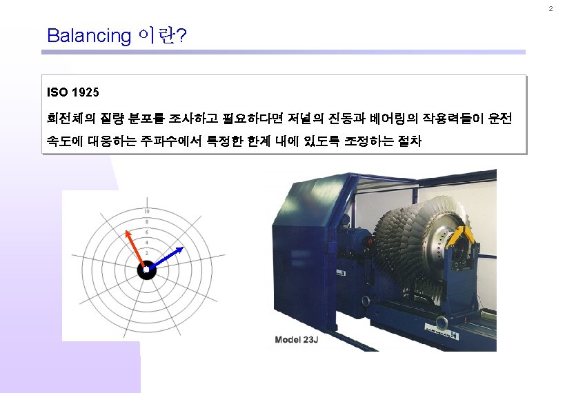
6 밸런싱 용어 n Unbalance l Unit: g·mm U=mxr

7 밸런싱 용어 n Unbalance l Static Unbalance l Couple Unbalance l Dynamic Unbalance Static Unbalance F 1 Couple Unbalance F 1 Dynamic Unbalance Principle inertia axis Cg Shaft axis Principle inertia axis Cg Cg F F 2 e F 2

8 허용잔류불평형 n Balancing Grade for Rigid Rotor l ISO 1940 l API

9 허용잔류불평형 n Balancing Grade for Rigid Rotor l ISO 1940

10 허용잔류불평형 n Example for Turbine Rotor l Rotor Weight 400 kg l Max. Speed 10, 000 rpm n ISO 1940 G 2. 5 n API

11 밸런싱 방법 n n n Graphic Method: Single Plane l Vector method l 4 Run method l Static couple method Influence Coefficient Method: Multi Plane l Standard influence coefficient method l Least square influence coefficient method Modal Method l Critical speed mode shape, Modal influence balancing coefficients
 Phase")
12 밸런싱 방법 n Phase Angle Phase Reference Pickup Heavy Spot Angle (θ) Phase Angle (θ) Vibration Pickup Phase Angle t High Spot Heavy Spot T High Spot
 Phase Reference Pickup Heavy Spot Angle (θ)")
13 밸런싱 방법 n Phase Angle (θ) Phase Reference Pickup Heavy Spot Angle (θ) - 90˚ Vibration Pickup + Phase Angle t - 90˚ High Spot Heavy Spot T High Spot
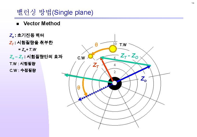
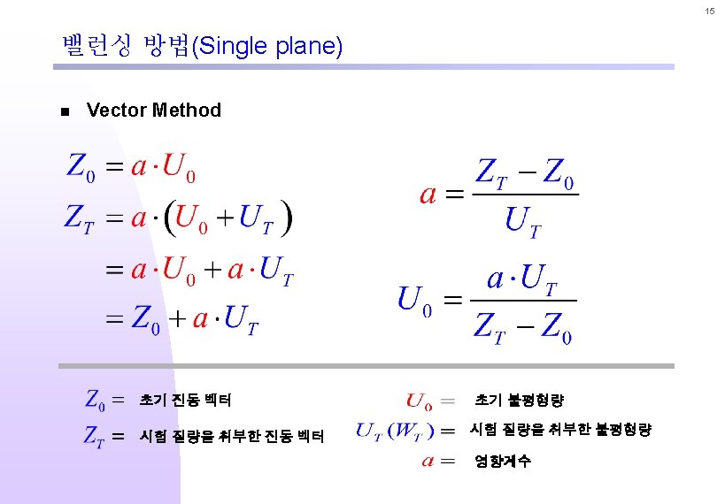
 n Vector Method 235 o q")
16 밸런싱 방법(Single plane) n Vector Method 235 o q
 F Pick Up N Pick Up Phase Plane 2 Plane")
17 밸런싱 방법(Two plane) F Pick Up N Pick Up Phase Plane 2 Plane 1
 n Initial vibration 90 o Phase F N d 180")
18 밸런싱 방법(Two plane) n Initial vibration 90 o Phase F N d 180 o g 0 o 180 o 0 o Rotation 360 o Plane 1 Plane 2
 n Trial weight – plane 1 90 o Phase N")
19 밸런싱 방법(Two plane) n Trial weight – plane 1 90 o Phase N F a. A g F 2 A N 2 180 o d 2 0 o 180 o 0 o Rotation 360 o Plane 1 Plane 2
 n Trial weight – plane 2 90 o Phase N")
20 밸런싱 방법(Two plane) n Trial weight – plane 2 90 o Phase N 3 F b. B N d 3 180 o B 0 o g 3 180 o F 3 Rotation 360 o Plane 1 Plane 2 0 o
 n Trial weight – plane 2 90 o f. B")
21 밸런싱 방법(Two plane) n Trial weight – plane 2 90 o f. B + q (a. A) = - F q. A + f (b. B) = - N N 180 o f b. B q Phase 0 o F 180 o B A -N Rotation 0 o q a. A f -F 360 o Plane 1 Plane 2

22 밸런싱 방법 n Static/Couple Method

23 밸런싱 방법 n Modal Balancing l Mode Shape l Modal Distribution

24 밸런싱 프로그램 n Input Module

25 밸런싱 프로그램 n Input Module

26 밸런싱 프로그램 n Input Module

27 밸런싱 프로그램 n Output Module
 n Class 1 : Rigid Rotor : These rotors may be")
28 회전체 분류(ISO) n Class 1 : Rigid Rotor : These rotors may be balanced in any two arbitrary axial planes and will remain in balance throughout the operating speed range (ex. , Gear wheel etc. ) n Class 2 : Quasi-flexible Rotors : These rotors are not perfectly rigid but may be adequately balanced in a low-speed balancing machine and will maintain smooth operation throughout the speed range (ex. , Shaft with grinding wheel, Jet-engine compressor rotor, Printingpress roller, Computer memory drum, Five-stage centrifugal pump, Multistage pump impeller, Impeller pump, Steam turbine rotor) Single and two plane constant-speed balancing is usually adequate
 n Class 3 : Flexible Rotors : These rotors cannot be")
29 회전체 분류(ISO) n Class 3 : Flexible Rotors : These rotors cannot be balanced in a low -speed balancing machine and require one or more high-speed trim plane corrections ( ex : Generator rotor etc. ) n Class 4 : Flexible-attachment Rotors : These rotors have components within themselves or flexibly attached (ex : Rotor with centrifugal switch) n Class 5 : Single-speed Flexible Rotors : These rotors could be class 3 flexible rotors but are balanced for operation at one speed only (ex : High-speed motor) A least-squared-error influence coefficient or combined modal technique is preferred
- Slides: 29