3 1 Process selection and the treatment process


: processes train of the water treatment plant")
: the capability of the various treatment techniques for removing contaminants")


: Typical shore intake structure")
 As far as possible, the")
- Slides: 12
3. 1 Process selection and the treatment process train Water treatment plant utilize a number of treatment processes to achieve the desired degree of treatment. Each stage of this processes has a function to remove a contaminant. Then the design engineer must evaluate numerous important factors in the selection of the treatment processes. These factors include finished water quality standards, state design criteria, constituents treated, topography and geology, hydraulic requirement, energy requirement and plant economics. The collective arrangement of various treatment processes is called flow schema, processes diagram, or processes train. In the most water treatment plant, the processes include:
1. Water intake 2. Coarse and fine screen 3. Pumps and pumping station 4. Coagulation and flocculation tanks 5. Sedimentation tanks 6. Filtration 7. Disinfection Figure 3. 1 shows the typical water treatment processes train. Also, table 3. 1 indicates the capability of the various treatment techniques for removing contaminants.
Fig. (3. 1): processes train of the water treatment plant
Table (3. 1): the capability of the various treatment techniques for removing contaminants
Fig. 3. 2 Floating intakes
Fig. 3. 3 Submerged intakes
Fig. 3. 4 Exposed or Tower intakes
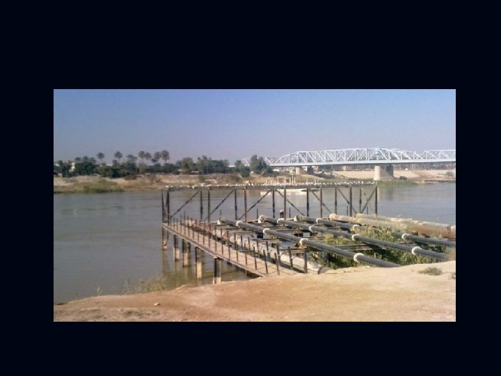
Fig. 3. 5 Shore-intake structure Fig. 3. 6 Pier structure
3. 2 Intake Structure The basic function of the intake structure is to help in safely withdrawing water from the source over predetermined pool levels and then to discharge this water into the withdrawal conduit (normally called intake conduit), through which it flows up to water treatment plant. Fig. (3. 2): Typical pier intake structure
Fig. (3. 3): Typical shore intake structure
3. 2. 1 Factors Governing Location of Intake 1) As far as possible, the site should be near the treatment plant so that the cost of conveying water to the city is less. 2) The intake must be located in the purer zone of the source to draw best quality water from the source, thereby reducing load on the treatment plant. 3) The intake must never be located at the downstream or in the vicinity of the point of disposal of wastewater. 4) The site should be such as to permit greater withdrawal of water, if required at a future date. 5) The intake must be located at a place from where it can draw water even during the driest period of the year. 6) The intake site should remain easily accessible during floods and should noy get flooded. Moreover, the flood waters should not be concentrated in the vicinity of the intake.