
22 July 2020 45 th Intl Nathiagali Summer


- Slides: 37
22 July, 2020 45 th Intl. Nathiagali Summer College Pulsed Power Technology and Applications “BAC and TCC methods of increasing efficiency and its application in development of power klystrons” Authors: Igor Guzilov, Chef Designer, NELSON Created AB, Uppsala, Sweden, igor. guzilov@nelsoncreated. com Daniel Lundberg, NELSON Created AB, Uppsala, Sweden, CEO, daniel. lundberg@nelsoncreated. com For a copy of this presentation please visit www. nelsoncreated. com NELSON rep. in Pakistan: Muntaha Industrial Trading Co. 61 -D/1, Sir Syed Road, Gulberg IIII, Lahore, Pakistan. Emial: m. ali@mitc. pk
Introduction Klystron amplifiers with RF power production efficiency above 80% are crucial for the future generation of large accelerators, such as the Compact Linear Collider (CLIC). Together with high efficiency, operating voltages below 80 k. V are of great interest. Lower voltages significantly reduce the length and weight of klystrons and eliminate the need of an oil tank for the modulator pulse transformer. Multi-beam technology is one of the key components in achieving such an improvement. Another important advancement is the application of the periodical permanent magnets (PPM) focusing system which can replace the standard focusing solenoid. This allows for reduced power consumption, weight and cost of the entire RF power source.
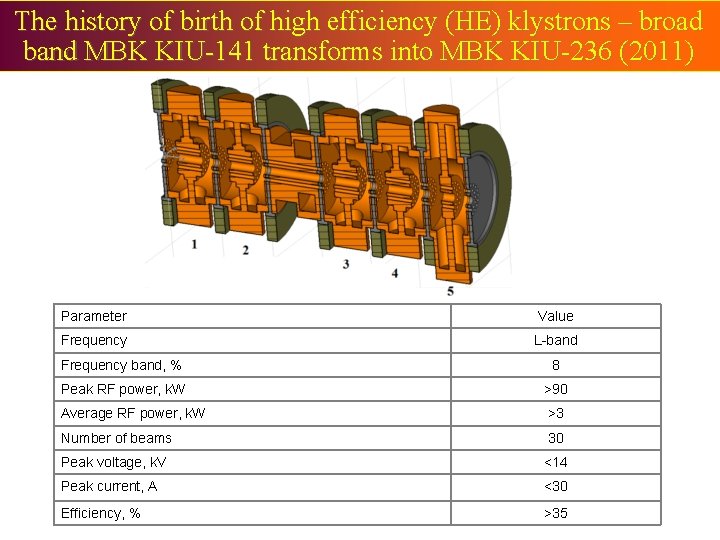
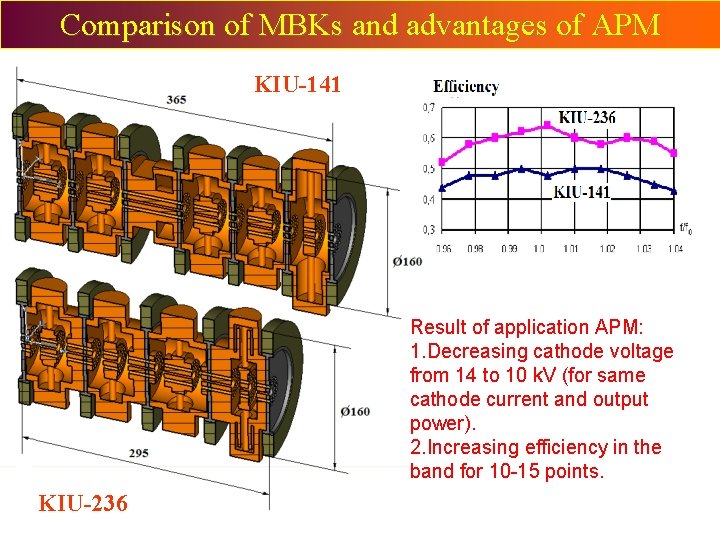
The history of birth of high efficiency (HE) klystrons – broad band MBK KIU-141 transforms into MBK KIU-236 (2011) Parameter Value Frequency L-band Frequency band, % 8 Peak RF power, k. W >90 Average RF power, k. W >3 Number of beams 30 Peak voltage, k. V <14 Peak current, A <30 Efficiency, % >35
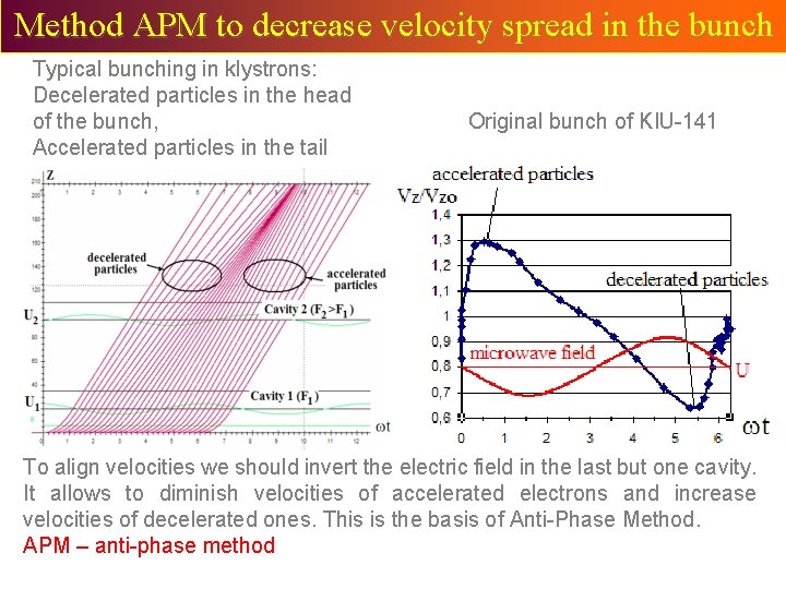
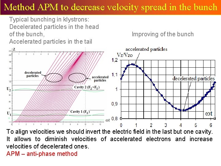
Method APM to decrease velocity spread in the bunch Typical bunching in klystrons: Decelerated particles in the head of the bunch, Accelerated particles in the tail Original bunch of KIU-141 To align velocities we should invert the electric field in the last but one cavity. It allows to diminish velocities of accelerated electrons and increase velocities of decelerated ones. This is the basis of Anti-Phase Method. APM – anti-phase method
Method APM to decrease velocity spread in the bunch Typical bunching in klystrons: Decelerated particles in the head of the bunch, Accelerated particles in the tail Improving of the bunch To align velocities we should invert the electric field in the last but one cavity. It allows to diminish velocities of accelerated electrons and increase velocities of decelerated ones. APM – anti-phase method
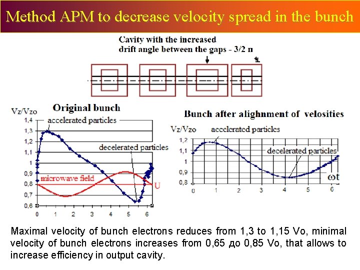
Method APM to decrease velocity spread in the bunch Maximal velocity of bunch electrons reduces from 1, 3 to 1, 15 Vo, minimal velocity of bunch electrons increases from 0, 65 до 0, 85 Vo, that allows to increase efficiency in output cavity.
Comparison of MBKs and advantages of APM KIU-141 Result of application APM: 1. Decreasing cathode voltage from 14 to 10 k. V (for same cathode current and output power). 2. Increasing efficiency in the band for 10 -15 points. KIU-236
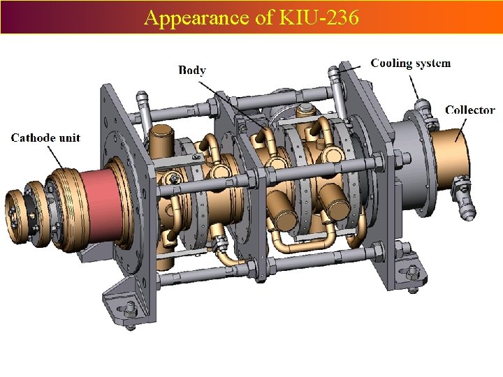
Appearance of KIU-236
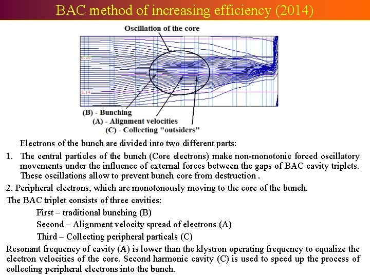
BAC method of increasing efficiency (2014) Electrons of the bunch are divided into two different parts: 1. The central particles of the bunch (Core electrons) make non-monotonic forced oscillatory movements under the influence of external forces between the gaps of BAC cavity triplets. These oscillations allow to prevent bunch core from destruction. 2. Peripheral electrons, which are monotonously moving to the core of the bunch. The BAC triplet consists of three cavities: First – traditional bunching (B) Second – Alignment velocity spread of electrons (A) Third – Collecting peripheral particals (C) Resonant frequency of cavity (A) is lower than the klystron operating frequency to equalize the electron velocities of the core. Second harmonic cavity (C) is used to speed up the process of collecting peripheral electrons into the bunch.
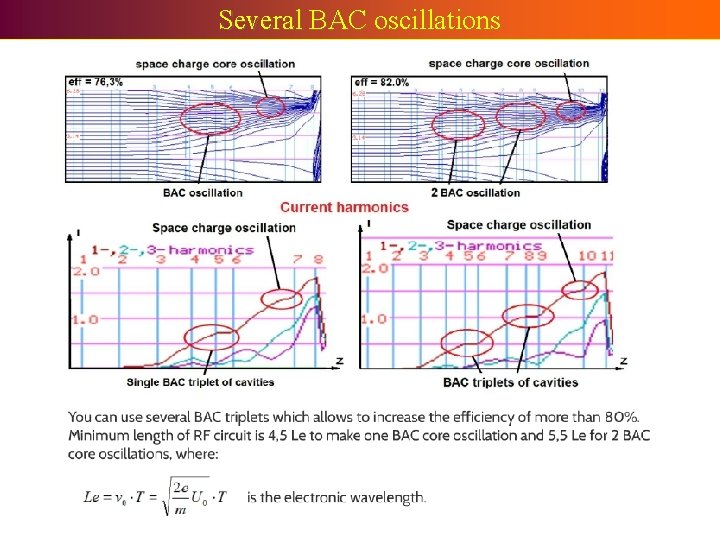
Several BAC oscillations
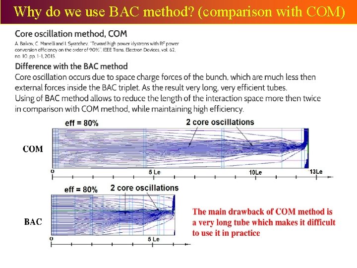
Why do we use BAC method? (comparison with COM)
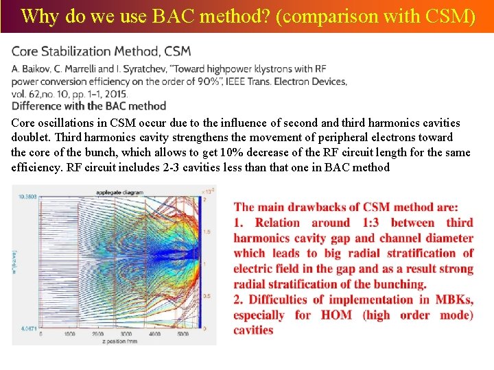
Why do we use BAC method? (comparison with CSM) Core oscillations in CSM occur due to the influence of second and third harmonics cavities doublet. Third harmonics cavity strengthens the movement of peripheral electrons toward the core of the bunch, which allows to get 10% decrease of the RF circuit length for the same efficiency. RF circuit includes 2 -3 cavities less than that one in BAC method
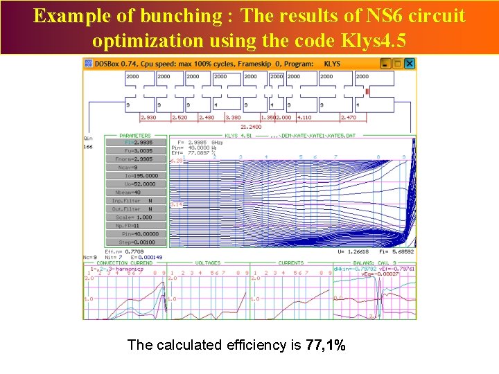
Example of bunching : The results of NS 6 circuit optimization using the code Klys 4. 5 The calculated efficiency is 77, 1%
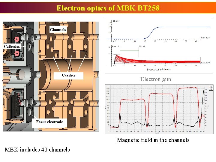
Electron optics of MBK BT 258 Space Charge De-bunching method Electron gun Magnetic field in the channels MBK includes 40 channels
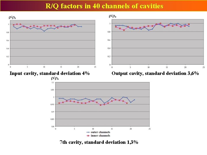
R/Q factors in 40 channels of cavities Input cavity, standard deviation 4% Output cavity, standard deviation 3, 6% 7 th cavity, standard deviation 1, 3%
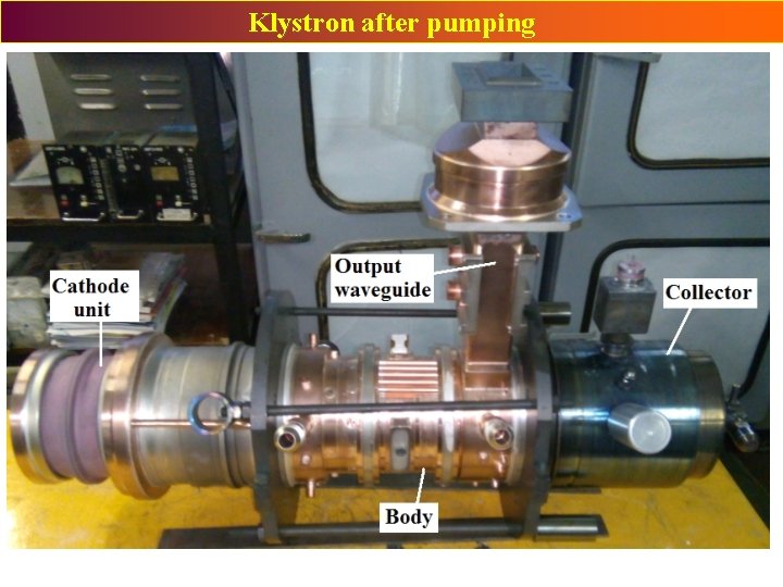
Klystron after pumping Space Charge De-bunching method
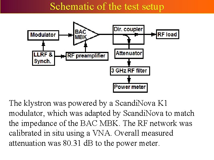
Schematic of the test setup The klystron was powered by a Scandi. Nova K 1 modulator, which was adapted by Scandi. Nova to match the impedance of the BAC MBK. The RF network was calibrated in situ using a VNA. Overall measured attenuation was 80. 31 d. B to the power meter.
BAC MBK installation at the test stand
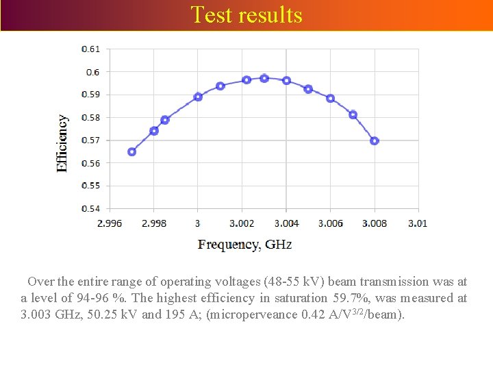
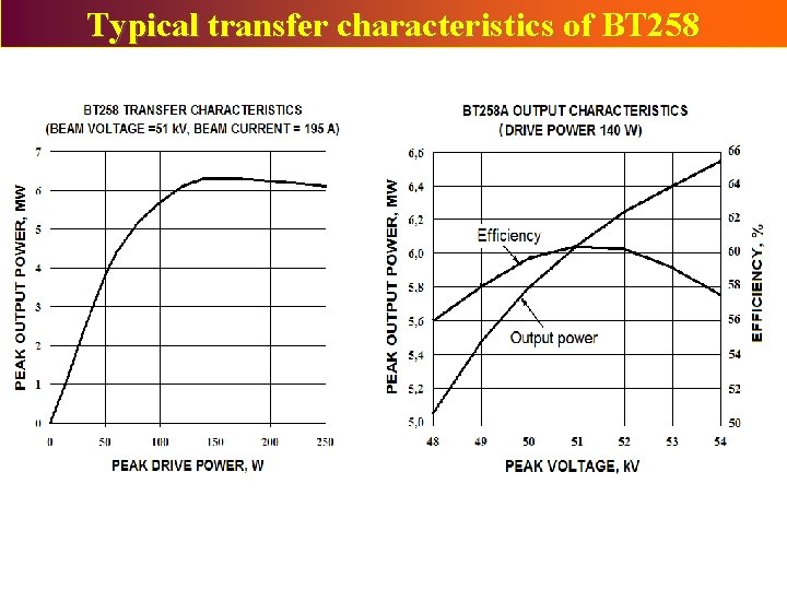
Test results Over the entire range of operating voltages (48 -55 k. V) beam transmission was at a level of 94 -96 %. The highest efficiency in saturation 59. 7%, was measured at 3. 003 GHz, 50. 25 k. V and 195 A; (microperveance 0. 42 A/V 3/2/beam).
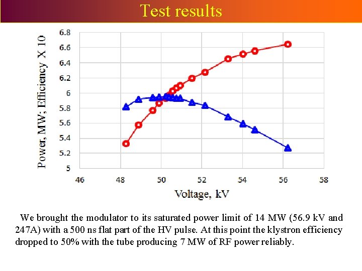
Test results We brought the modulator to its saturated power limit of 14 MW (56. 9 k. V and 247 A) with a 500 ns flat part of the HV pulse. At this point the klystron efficiency dropped to 50% with the tube producing 7 MW of RF power reliably.
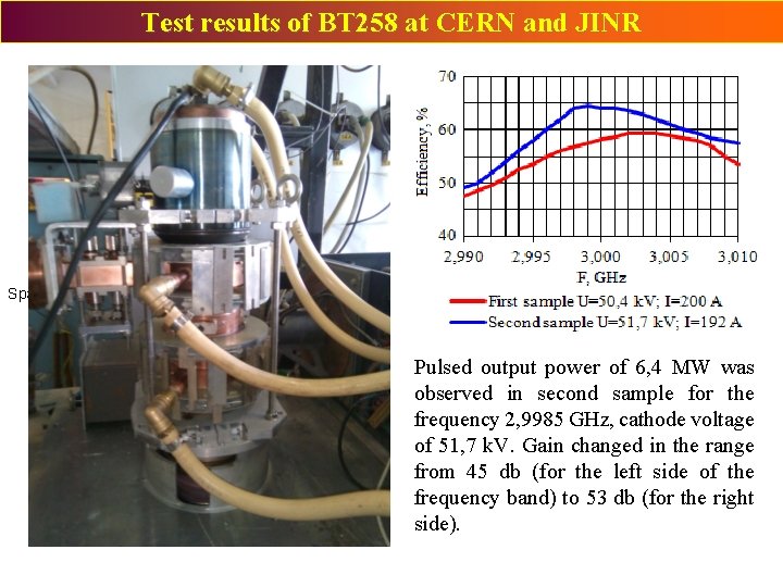
Test results of BT 258 at CERN and JINR Space Charge De-bunching method Pulsed output power of 6, 4 MW was observed in second sample for the frequency 2, 9985 GHz, cathode voltage of 51, 7 k. V. Gain changed in the range from 45 db (for the left side of the frequency band) to 53 db (for the right side).
Typical transfer characteristics of BT 258
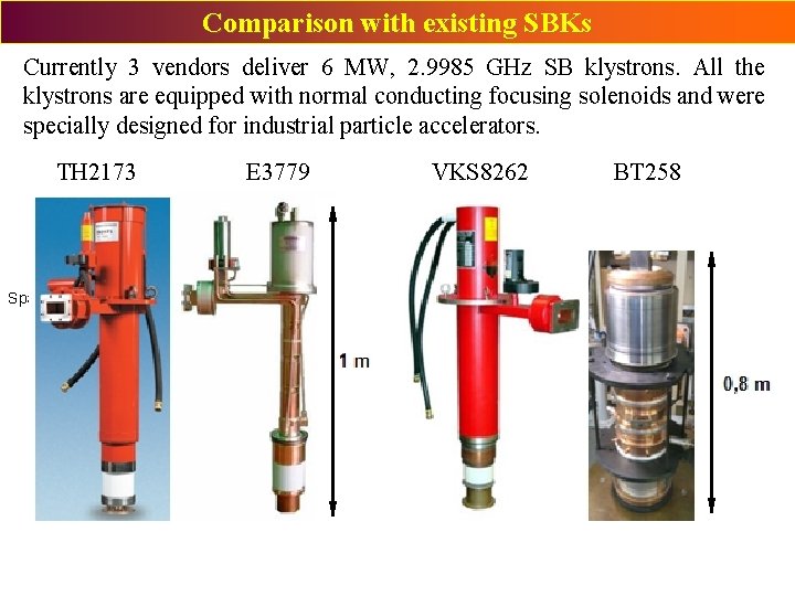
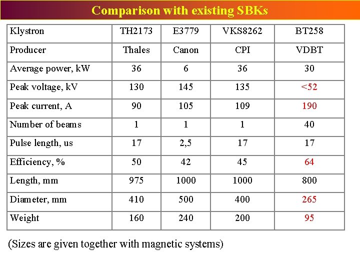
Comparison with existing SBKs Currently 3 vendors deliver 6 MW, 2. 9985 GHz SB klystrons. All the klystrons are equipped with normal conducting focusing solenoids and were specially designed for industrial particle accelerators. TH 2173 E 3779 VKS 8262 BT 258 Space Charge De-bunching method
Comparison with existing SBKs Klystron TH 2173 E 3779 VKS 8262 BT 258 Producer Thales Canon CPI VDBT Average power, k. W 36 6 36 30 Peak voltage, k. V 130 145 135 <52 Peak current, A 90 105 109 190 Number of beams 1 1 1 40 Pulse length, us 17 2, 5 17 17 Efficiency, % 50 42 45 64 Length, mm 975 1000 800 Diameter, mm 410 500 400 265 Weight 160 240 200 95 (Sizes are given together with magnetic systems)
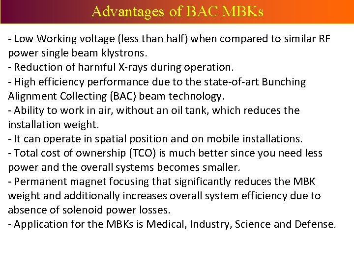
Advantages of BAC MBKs - Low Working voltage (less than half) when compared to similar RF power single beam klystrons. - Reduction of harmful X-rays during operation. - High efficiency performance due to the state-of-art Bunching Alignment Collecting (BAC) beam technology. - Ability to work in air, without an oil tank, which reduces the installation weight. - It can operate in spatial position and on mobile installations. - Total cost of ownership (TCO) is much better since you need less power and the overall systems becomes smaller. - Permanent magnet focusing that significantly reduces the MBK weight and additionally increases overall system efficiency due to absence of solenoid power losses. - Application for the MBKs is Medical, Industry, Science and Defense.
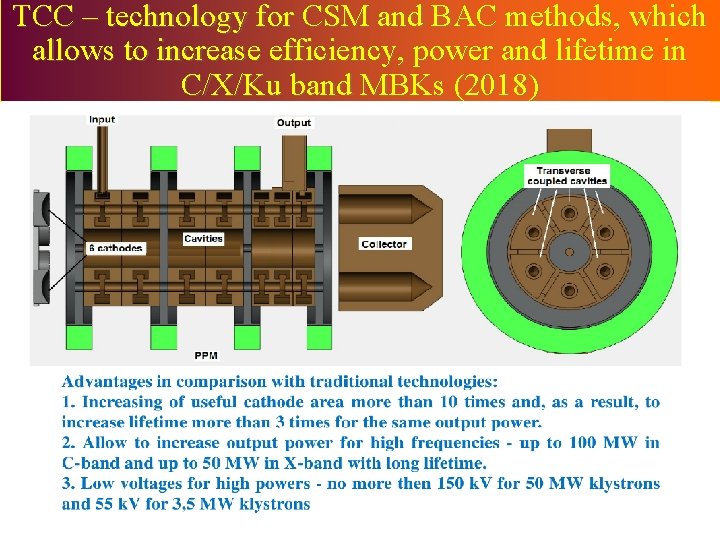
TCC – technology for CSM and BAC methods, which allows to increase efficiency, power and lifetime in C/X/Ku band MBKs (2018)
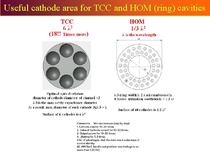
Useful cathode area for TCC and HOM (ring) cavities
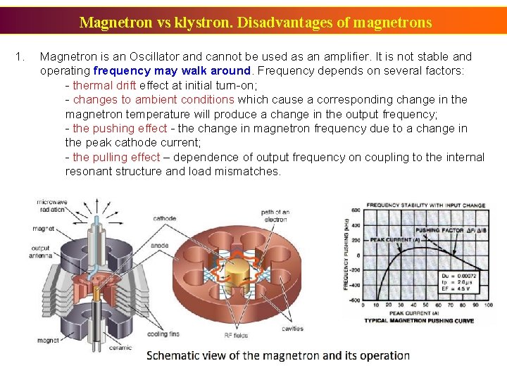
Magnetron vs klystron. Disadvantages of magnetrons 1. Magnetron is an Oscillator and cannot be used as an amplifier. It is not stable and operating frequency may walk around. Frequency depends on several factors: - thermal drift effect at initial turn-on; - changes to ambient conditions which cause a corresponding change in the magnetron temperature will produce a change in the output frequency; - the pushing effect - the change in magnetron frequency due to a change in the peak cathode current; - the pulling effect – dependence of output frequency on coupling to the internal resonant structure and load mismatches.
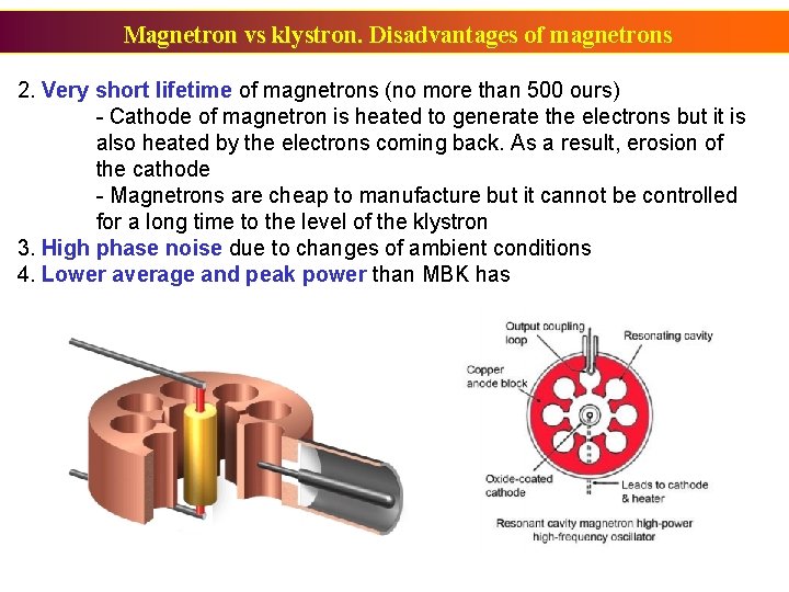
Magnetron vs klystron. Disadvantages of magnetrons 2. Very short lifetime of magnetrons (no more than 500 ours) - Cathode of magnetron is heated to generate the electrons but it is also heated by the electrons coming back. As a result, erosion of the cathode - Magnetrons are cheap to manufacture but it cannot be controlled for a long time to the level of the klystron 3. High phase noise due to changes of ambient conditions 4. Lower average and peak power than MBK has
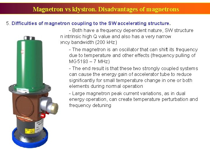
Magnetron vs klystron. Disadvantages of magnetrons 5. Difficulties of magnetron coupling to the SW accelerating structure. - Both have a frequency dependent nature, SW structure has an intrinsic high Q value and also has a very narrow frequency bandwidth (200 k. Hz) - The magnetron is an oscillator that can shift its frequency due to temperature and other effects (frequency pulling of MG 5193 – 7 MHz) - The end result is that these two strongly coupled systems can cause the energy gain of accelerator tube to reduce significantly for small temperature change in one or both elements during normal operation - Large magnetron peak current variations, as in dual energy operation, can create temperature perturbation and frequency detuning
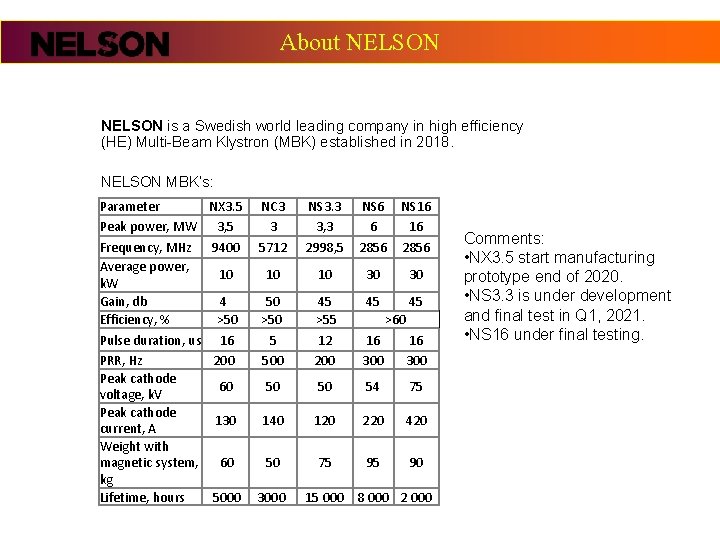
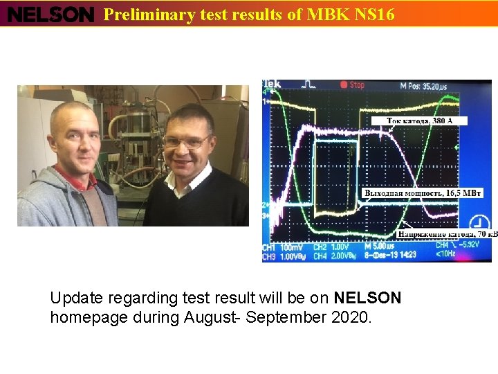
About NELSON is a Swedish world leading company in high efficiency (HE) Multi-Beam Klystron (MBK) established in 2018. NELSON MBK’s: Parameter NX 3. 5 Peak power, MW 3, 5 NC 3 3 NS 3. 3 3, 3 NS 6 6 NS 16 16 Frequency, MHz Average power, k. W Gain, db Efficiency, % Pulse duration, us PRR, Hz Peak cathode voltage, k. V Peak cathode current, A Weight with magnetic system, kg Lifetime, hours 9400 5712 2998, 5 2856 10 10 10 30 30 4 >50 16 200 50 >50 5 500 45 >55 12 200 45 45 16 300 60 50 50 54 75 130 140 120 220 420 60 50 75 95 90 5000 3000 >60 15 000 8 000 2 000 Comments: • NX 3. 5 start manufacturing prototype end of 2020. • NS 3. 3 is under development and final test in Q 1, 2021. • NS 16 under final testing.
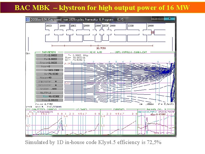
BAC MBK – klystron for high output power of 16 MW Simulated by 1 D in-house code Klys 4. 5 efficiency is 72, 5%
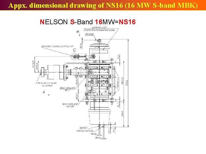
Appx. dimensional drawing of NS 16 (16 MW S-band MBK) NELSON S-Band 16 MW=NS 16
Preliminary test results of MBK NS 16 Update regarding test result will be on NELSON homepage during August- September 2020.
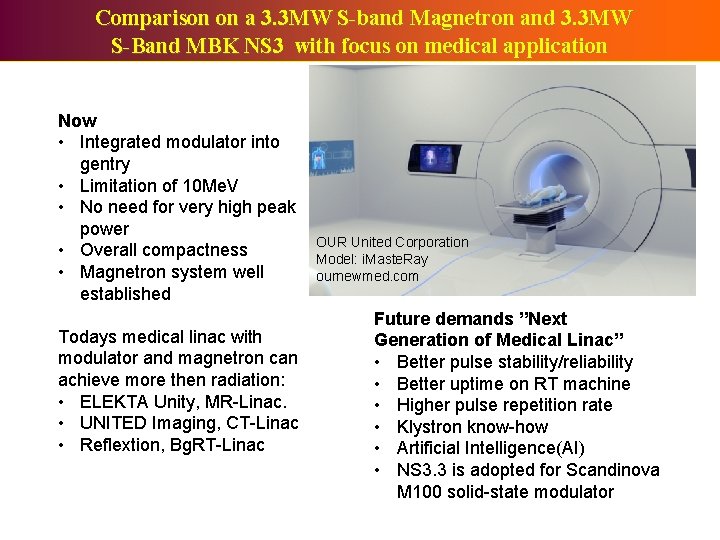
Comparison on a 3. 3 MW S-band Magnetron and 3. 3 MW S-Band MBK NS 3 with focus on medical application Now • Integrated modulator into gentry • Limitation of 10 Me. V • No need for very high peak power • Overall compactness • Magnetron system well established Todays medical linac with modulator and magnetron can achieve more then radiation: • ELEKTA Unity, MR-Linac. • UNITED Imaging, CT-Linac • Reflextion, Bg. RT-Linac OUR United Corporation Model: i. Maste. Ray ournewmed. com Future demands ”Next Generation of Medical Linac” • Better pulse stability/reliability • Better uptime on RT machine • Higher pulse repetition rate • Klystron know-how • Artificial Intelligence(AI) • NS 3. 3 is adopted for Scandinova M 100 solid-state modulator
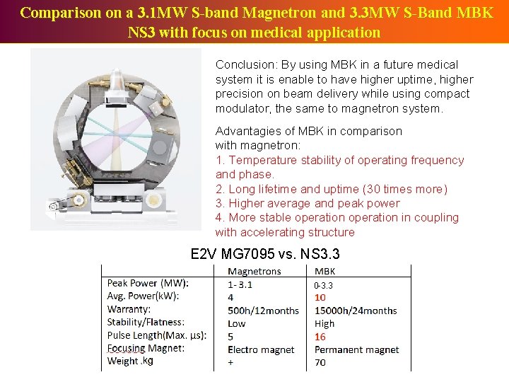
Comparison on a 3. 1 MW S-band Magnetron and 3. 3 MW S-Band MBK NS 3 with focus on medical application Conclusion: By using MBK in a future medical system it is enable to have higher uptime, higher precision on beam delivery while using compact modulator, the same to magnetron system. Advantagies of MBK in comparison with magnetron: 1. Temperature stability of operating frequency and phase. 2. Long lifetime and uptime (30 times more) 3. Higher average and peak power 4. More stable operation in coupling with accelerating structure E 2 V MG 7095 vs. NS 3. 3 0 -3. 3
Thank you for your attention PLEASE KEEP SOCIAL DISTANCE OF 2 PCS MBK A special thank you to NCP and PIEAS for your inviation