
20 th ATF Program Advisory Committee and Users


- Slides: 17
20 th ATF Program Advisory Committee and Users’ Meeting December 5 -7, 2016 Igor Pogorelsky Overview of CO 2 Laser R&D Program
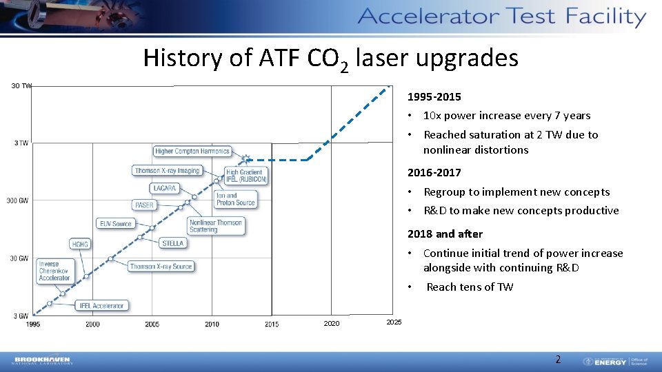
History of ATF CO 2 laser upgrades 30 TW 1995 -2015 • 10 x power increase every 7 years • Reached saturation at 2 TW due to nonlinear distortions 2016 -2017 • Regroup to implement new concepts • R&D to make new concepts productive 2018 and after • Continue initial trend of power increase alongside with continuing R&D • Reach tens of TW 2020 2025 2
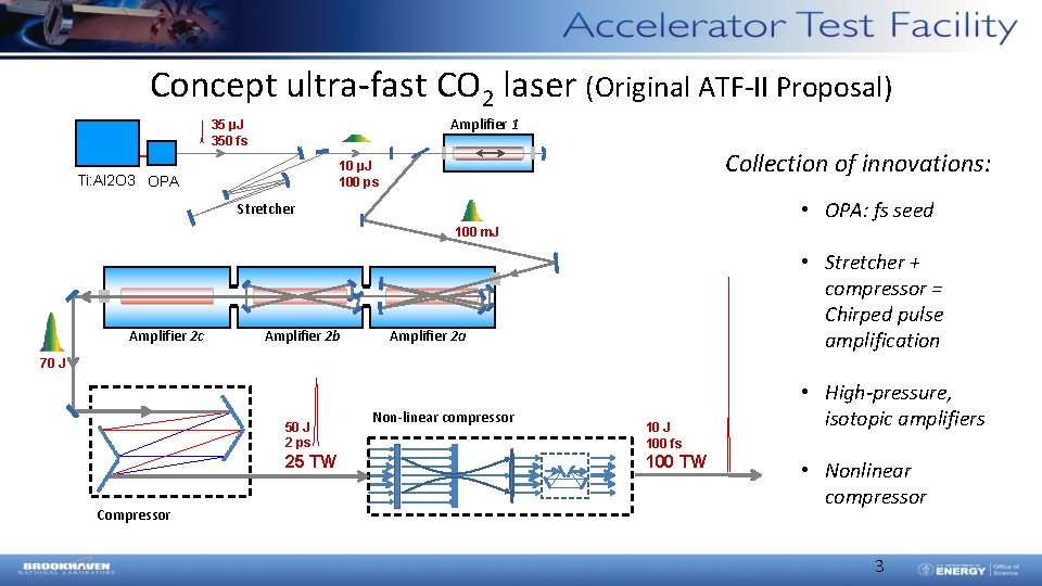
Concept ultra-fast CO 2 laser (Original ATF-II Proposal) Amplifier 1 35 µJ 350 fs Collection of innovations: 10 µJ 100 ps Ti: Al 2 O 3 OPA • OPA: fs seed Stretcher 100 m. J Amplifier 2 c Amplifier 2 b • Stretcher + compressor = Chirped pulse amplification Amplifier 2 a 70 J 50 J 2 ps 25 TW Compressor Non-linear compressor 10 J 100 fs 100 TW • High-pressure, isotopic amplifiers • Nonlinear compressor 3
Present-day configuration Ti: Al 2 O 3 OPA Amplifier 1 15 µJ 350 fs Collection of innovations: 1 µJ 80 ps 10 m. J 25 ps Stretcher 20 J Recent past --- Regular gas Isotopes 2017 R&D Amplifier 2 • OPA: fs seed • Stretcher + compressor = Chirped pulse amplification • High-pressure, isotopic amplifiers 8 -9 J Regular gas Near future --Compressor Isotopes • Nonlinear compressor 4
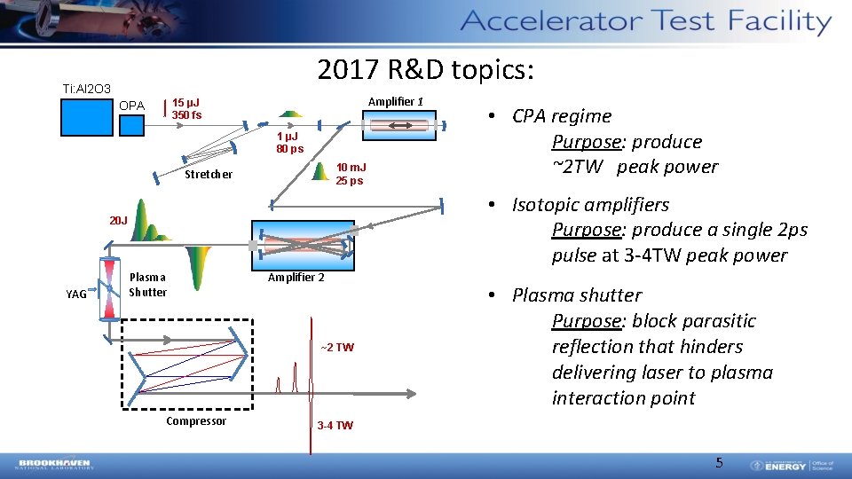
2017 R&D topics: Ti: Al 2 O 3 Amplifier 1 15 µJ 350 fs OPA 1 µJ 80 ps 10 m. J 25 ps Stretcher • Isotopic amplifiers Purpose: produce a single 2 ps pulse at 3 -4 TW peak power 20 J YAG • CPA regime Purpose: produce ~2 TW peak power Plasma Shutter Amplifier 2 ~2 TW Compressor • Plasma shutter Purpose: block parasitic reflection that hinders delivering laser to plasma interaction point 3 -4 TW 5
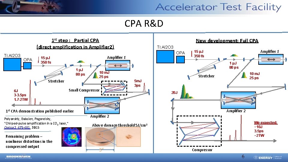
CPA R&D 1 st step : Partial CPA (direct amplification in Amplifier 2) Ti: Al 2 O 3 OPA 1 µJ 80 ps Stretcher OPA Amplifier 1 15 µJ 350 fs 1 µJ 80 ps 10 m. J 25 ps Stretcher 5 m. J 3 ps Small Compressor 1 st CPA demonstration published earlier Polyanskiy, Babzien, Pogorelsky, "Chirped-pulse amplification in a CO 2 laser, " Optica 2, 675 -681, 2015 Remaining problem – nonlinear distortions in the compressed output Ti: Al 2 O 3 Amplifier 1 15 µJ 350 fs 6 J 3 -3. 5 ps 1. 7 -2 TW New development: Full CPA 20 J Amplifier 2 We expected: ~10 J 3. 5 ps ~2 TW Above damage threshold 5 J/cm 2 3” Compressor 6
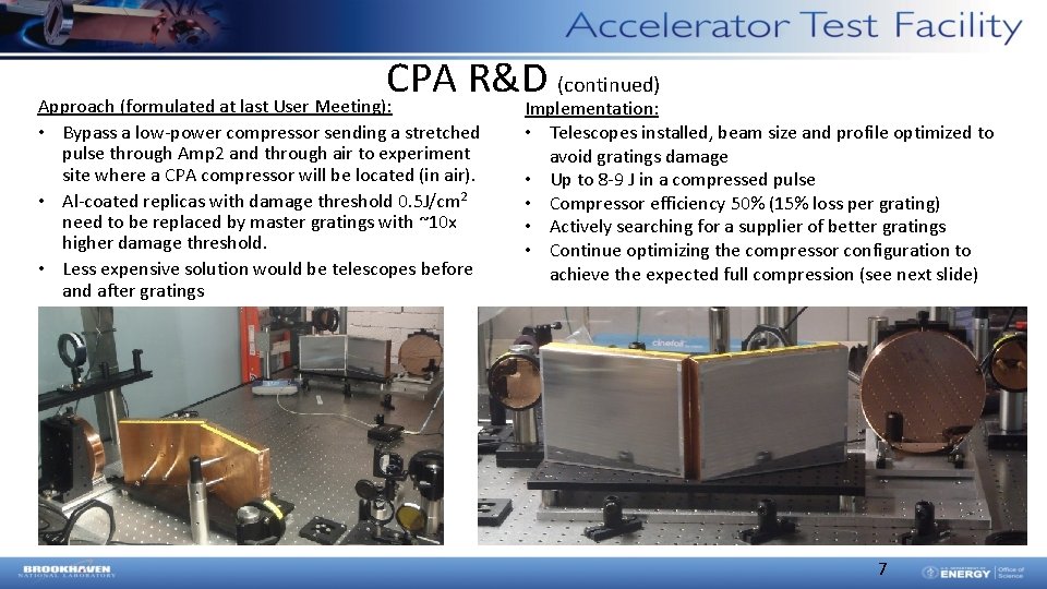
CPA R&D (continued) Approach (formulated at last User Meeting): • Bypass a low-power compressor sending a stretched pulse through Amp 2 and through air to experiment site where a CPA compressor will be located (in air). • Al-coated replicas with damage threshold 0. 5 J/cm 2 need to be replaced by master gratings with ~10 x higher damage threshold. • Less expensive solution would be telescopes before and after gratings Implementation: • Telescopes installed, beam size and profile optimized to avoid gratings damage • Up to 8 -9 J in a compressed pulse • Compressor efficiency 50% (15% loss per grating) • Actively searching for a supplier of better gratings • Continue optimizing the compressor configuration to achieve the expected full compression (see next slide) 7 7
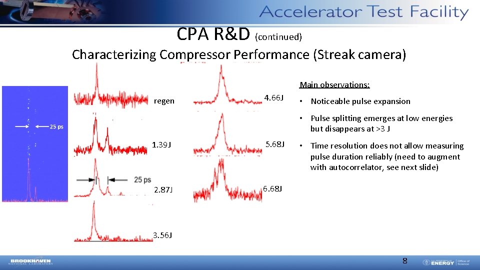
CPA R&D (continued) Characterizing Compressor Performance (Streak camera) Main observations: regen 4. 66 J • Noticeable pulse expansion • Pulse splitting emerges at low energies but disappears at >3 J 1. 39 J 5. 68 J 2. 87 J 6. 68 J • Time resolution does not allow measuring pulse duration reliably (need to augment with autocorrelator, see next slide) 3. 56 J 8
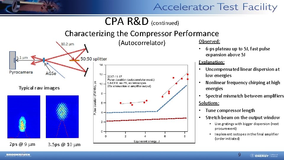
CPA R&D (continued) Characterizing the Compressor Performance (Autocorrelator) Typical raw images 2 ps @ 9 mm 3. 5 ps @ 10 mm Observed: • 6 -ps plateau up to 5 J, fast pulse expansion above 5 J Explanation: • Uncompensated linear dispersion at low energies • Nonlinear frequency chirping at high energies • Spectral mismatch between amplifiers Solutions: • Tune compressor length • Stretch beam on the output window • Use gratings with bigger dispersion (next procurement) • Implement isotopes in the final amplifier (order initiated) 9
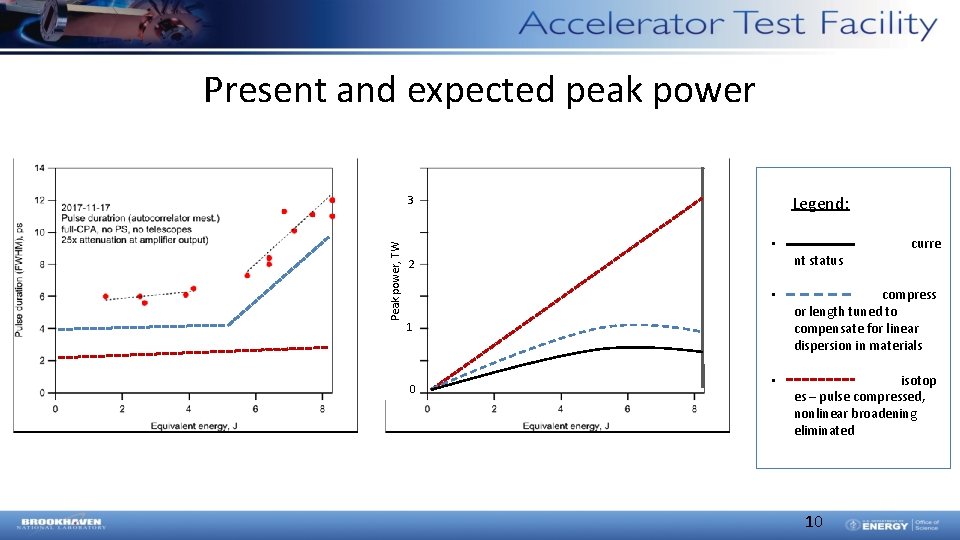
Present and expected peak power Legend: Peak power, TW 3 0 2 • curre nt status • compress or length tuned to compensate for linear dispersion in materials • isotop es – pulse compressed, nonlinear broadening eliminated 0 10
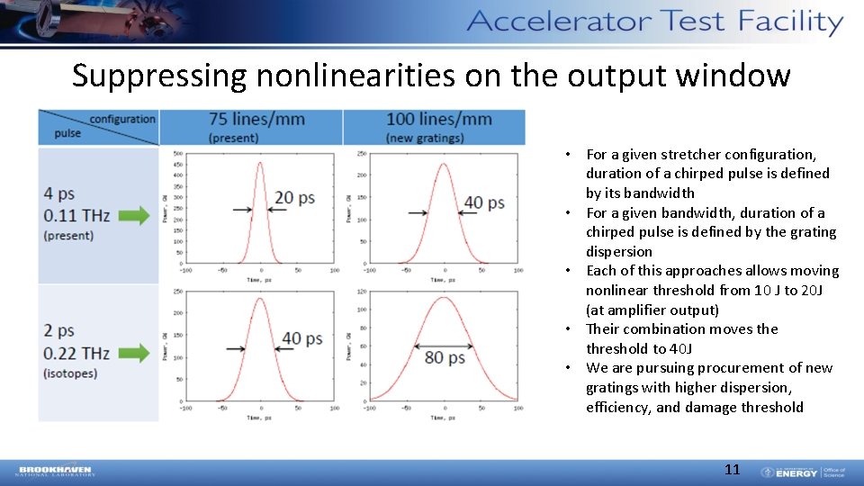
Suppressing nonlinearities on the output window • For a given stretcher configuration, duration of a chirped pulse is defined by its bandwidth • For a given bandwidth, duration of a chirped pulse is defined by the grating dispersion • Each of this approaches allows moving nonlinear threshold from 10 J to 20 J (at amplifier output) • Their combination moves the threshold to 40 J • We are pursuing procurement of new gratings with higher dispersion, efficiency, and damage threshold 11
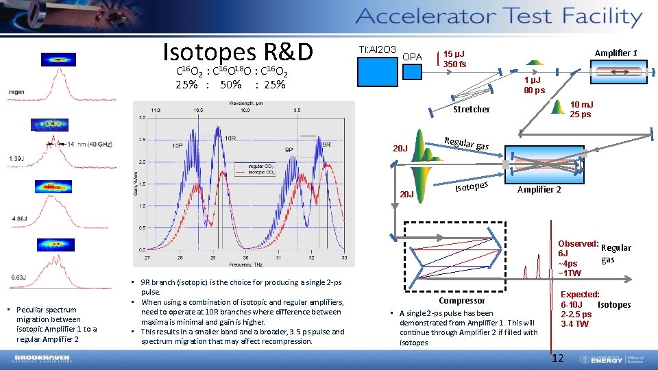
Isotopes R&D Ti: Al 2 O 3 OPA C 16 O 2 : C 16 O 18 O : C 16 O 2 25% : 50% : 25% Amplifier 1 15 µJ 350 fs 1 µJ 80 ps 10 m. J 25 ps Stretcher 20 J • Peculiar spectrum migration between isotopic Amplifier 1 to a regular Amplifier 2 • 9 R branch (isotopic) is the choice for producing a single 2 -ps pulse. • When using a combination of isotopic and regular amplifiers, need to operate at 10 R branches where difference between maxima is minimal and gain is higher. • This results in a smaller band a broader, 3. 5 ps pulse and spectrum migration that may affect recompression. Regular gas Isotopes Amplifier 2 Observed: Regular 6 J gas ~4 ps ~1 TW Compressor • A single 2 -ps pulse has been demonstrated from Amplifier 1. This will continue through Amplifier 2 if filled with isotopes Expected: 6 -10 J Isotopes 2 -2. 5 ps 3 -4 TW 12
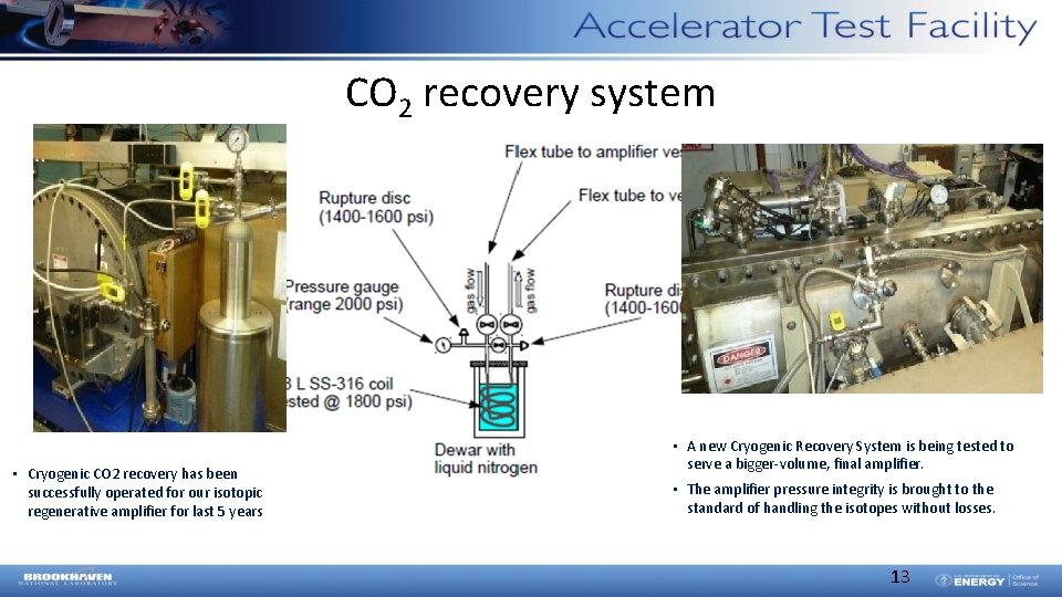
CO 2 recovery system • Cryogenic CO 2 recovery has been successfully operated for our isotopic regenerative amplifier for last 5 years • A new Cryogenic Recovery System is being tested to serve a bigger-volume, final amplifier. • The amplifier pressure integrity is brought to the standard of handling the isotopes without losses. 13
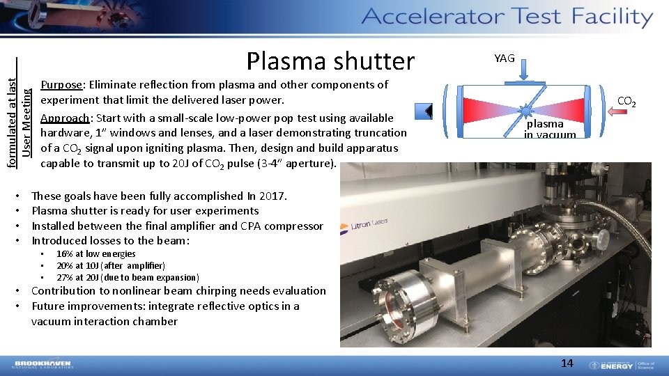
formulated at last User Meeting • • Plasma shutter Purpose: Eliminate reflection from plasma and other components of experiment that limit the delivered laser power. Approach: Start with a small-scale low-power pop test using available hardware, 1” windows and lenses, and a laser demonstrating truncation of a CO 2 signal upon igniting plasma. Then, design and build apparatus capable to transmit up to 20 J of CO 2 pulse (3 -4” aperture). YAG CO 2 plasma in vacuum These goals have been fully accomplished In 2017. Plasma shutter is ready for user experiments Installed between the final amplifier and CPA compressor Introduced losses to the beam: • • • 16% at low energies 20% at 10 J (after amplifier) 27% at 20 J (due to beam expansion) • Contribution to nonlinear beam chirping needs evaluation • Future improvements: integrate reflective optics in a vacuum interaction chamber 14
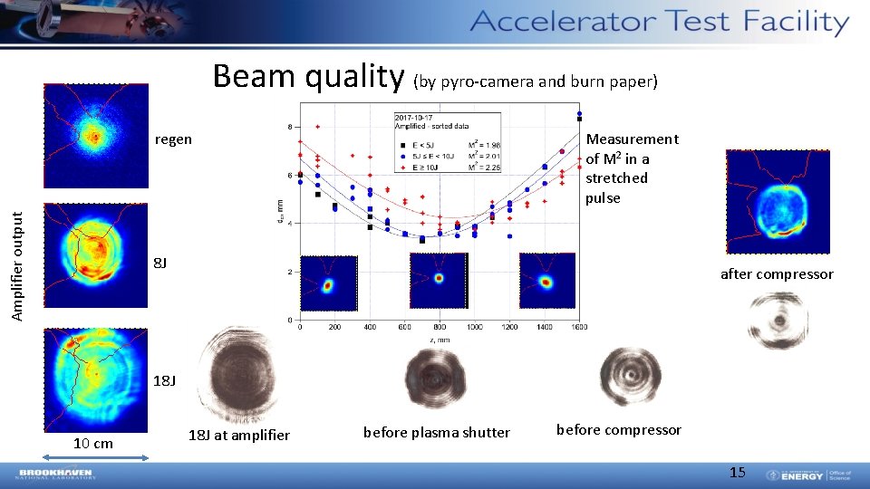
Beam quality (by pyro-camera and burn paper) Measurement of M 2 in a stretched pulse Amplifier output regen 8 J after compressor 18 J 10 cm 18 J at amplifier before plasma shutter before compressor 15
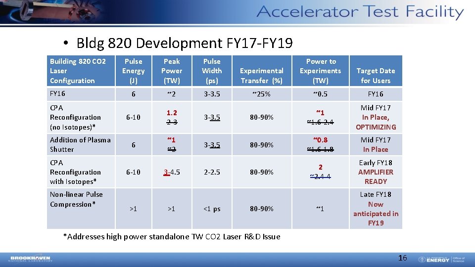
• Bldg 820 Development FY 17 -FY 19 Building 820 CO 2 Laser Configuration FY 16 CPA Reconfiguration (no Isotopes)* Addition of Plasma Shutter CPA Reconfiguration with Isotopes* Non-linear Pulse Compression* Pulse Energy (J) Peak Power (TW) Pulse Width (ps) 6 ~2 3 -3. 5 6 -10 1. 2 2 -3 6 ~1 ~2 6 -10 >1 3 -4. 5 >1 Experimental Transfer (%) Power to Experiments (TW) Target Date for Users ~25% ~0. 5 FY 16 3 -3. 5 80 -90% ~1 ~1. 6 -2. 4 Mid FY 17 In Place, OPTIMIZING 3 -3. 5 80 -90% ~0. 8 ~1. 6 -1. 8 Mid FY 17 In Place 80 -90% 2 ~2. 4 -4 Early FY 18 AMPLIFIER READY ~1 Late FY 18 Now anticipated in FY 19 2 -2. 5 <1 ps 80 -90% *Addresses high power standalone TW CO 2 Laser R&D Issue 16
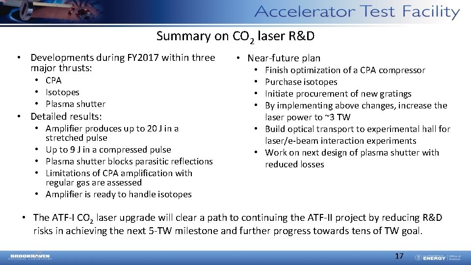
Summary on CO 2 laser R&D • Developments during FY 2017 within three major thrusts: • CPA • Isotopes • Plasma shutter • Detailed results: • Amplifier produces up to 20 J in a stretched pulse • Up to 9 J in a compressed pulse • Plasma shutter blocks parasitic reflections • Limitations of CPA amplification with regular gas are assessed • Amplifier is ready to handle isotopes • Near-future plan Finish optimization of a CPA compressor Purchase isotopes Initiate procurement of new gratings By implementing above changes, increase the laser power to ~3 TW • Build optical transport to experimental hall for laser/e-beam interaction experiments • Work on next design of plasma shutter with reduced losses • • • The ATF-I CO 2 laser upgrade will clear a path to continuing the ATF-II project by reducing R&D risks in achieving the next 5 -TW milestone and further progress towards tens of TW goal. 17