
2 Direct Inverse Kinematics Robotics Instructor Dr Wajdi
2 - Direct & Inverse Kinematics Robotics Instructor: Dr. Wajdi Sadik
Direct & Inverse Kinematics l Spatial description and transformation l Direct kinematics – Link description – Link-connection description – Affixing frames to links – Manipulator kinematics – Example l Inverse kinematics 1 -Spatial description and transformation, 2 -Direct & Inverse Kinematics 2
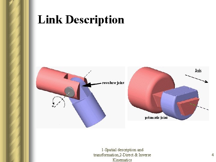
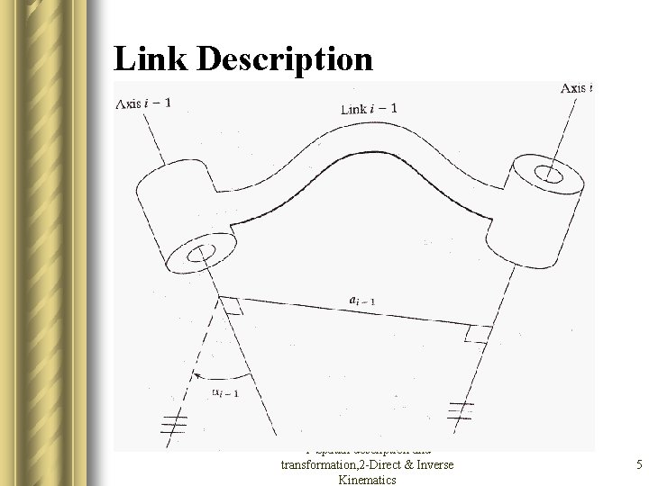
Link Description l Think of the manipulator as a chain of bodies (links) connected by joints. l We will consider manipulators constructed with joints of 1 degree of freedom (DOF): revolute and prismatic joints. l The links are numbered from 0 (immobile base) to n (free end of the arm). 1 -Spatial description and transformation, 2 -Direct & Inverse Kinematics 3
Link Description 1 -Spatial description and transformation, 2 -Direct & Inverse Kinematics 4
Link Description 1 -Spatial description and transformation, 2 -Direct & Inverse Kinematics 5
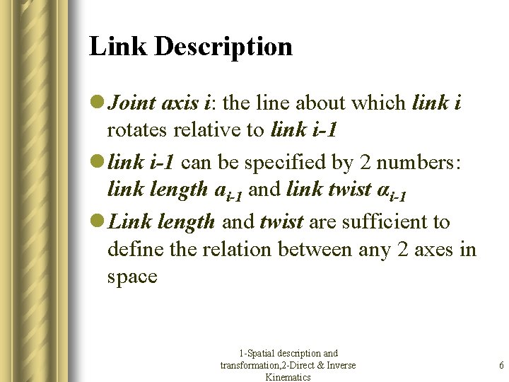
Link Description l Joint axis i: the line about which link i rotates relative to link i-1 l link i-1 can be specified by 2 numbers: link length ai-1 and link twist αi-1 l Link length and twist are sufficient to define the relation between any 2 axes in space 1 -Spatial description and transformation, 2 -Direct & Inverse Kinematics 6
Direct & Inverse Kinematics l Spatial description and transformation l Direct kinematics – Link description – Link-connection description – Affixing frames to links – Manipulator kinematics – Example l Inverse kinematics 1 -Spatial description and transformation, 2 -Direct & Inverse Kinematics 7
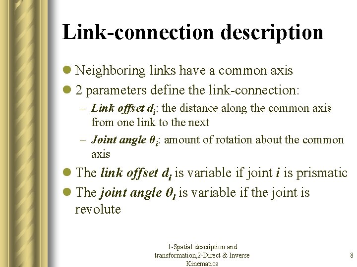
Link-connection description l Neighboring links have a common axis l 2 parameters define the link-connection: – Link offset di: the distance along the common axis from one link to the next – Joint angle θi: amount of rotation about the common axis l The link offset di is variable if joint i is prismatic l The joint angle θi is variable if the joint is revolute 1 -Spatial description and transformation, 2 -Direct & Inverse Kinematics 8
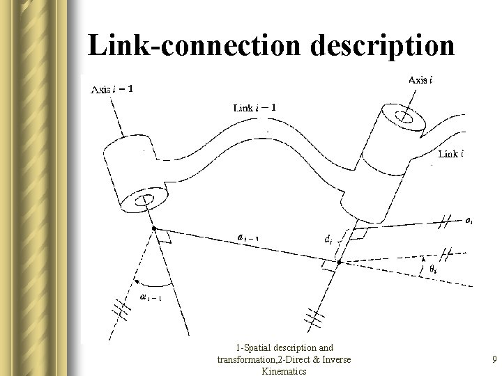
Link-connection description 1 -Spatial description and transformation, 2 -Direct & Inverse Kinematics 9
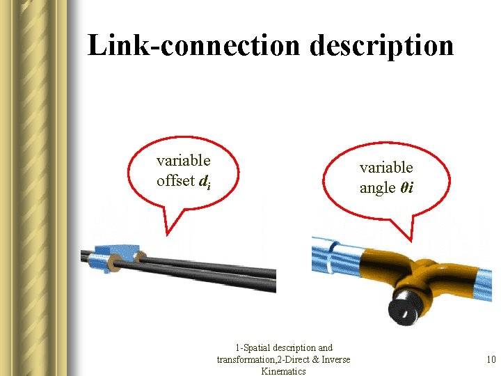
Link-connection description variable offset di variable angle θi 1 -Spatial description and transformation, 2 -Direct & Inverse Kinematics 10
First and last link in the chain l The link length ai, and the link twist αi depend on the joint axis i and i+1. l Convention: a 0=an=0 and α 0=αn=0 l Similar for the link offset di and the joint angle θi : if joint 1 is revolute, then d 1=0. if joint 1 is prismatic, then θ 1=0. 1 -Spatial description and transformation, 2 -Direct & Inverse Kinematics 11
Denavit-Hartenberg notation l Any robot can be described kinematically by 4 quantities for each link: – 2 for the link – 2 to describe the link’s connection l For revolute joints, θi is called the joint variable (the other 3 quantities are fixed). l For prismatic joints, di is the joint variable (the other 3 quantities are fixed). 1 -Spatial description and transformation, 2 -Direct & Inverse Kinematics 12
Denavit-Hartenberg notation l The definition of mechanics by means of these quantities is called the Denavit. Hartenberg notation. 1 -Spatial description and transformation, 2 -Direct & Inverse Kinematics 13
Direct & Inverse Kinematics l Spatial description and transformation l Direct kinematics – Link description – Link-connection description – Affixing frames to links – Manipulator kinematics – Example l Inverse kinematics 1 -Spatial description and transformation, 2 -Direct & Inverse Kinematics 14
Affixing frames to links l We define a frame attached to each link: frame {i} is attached rigidly to link {i} l Convention: – the origin is located where the “link length line” ai intersects the joint axis – the Z axis is coincident with the joint axis – the X axis points along ai, to the direction from joint i to joint i+1 – The Y axis is formed by the right-hand rule 1 -Spatial description and transformation, 2 -Direct & Inverse Kinematics 15
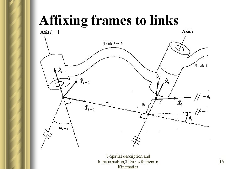
Affixing frames to links 1 -Spatial description and transformation, 2 -Direct & Inverse Kinematics 16
First and last link in the chain l Frame {0} is the immobile base (link 0) of the robot. Thus a 0=0 and α 0=0. l If joint 1 is revolute, then d 1=0. If joint 1 is prismatic, then θ 1=0. l If joint n is revolute, then Xn’s direction is the same as Xn-1’s (θ 1=0), and {n}’s origin is the intersection of Xn-1 and axis n when dn=0. 1 -Spatial description and transformation, 2 -Direct & Inverse Kinematics 17
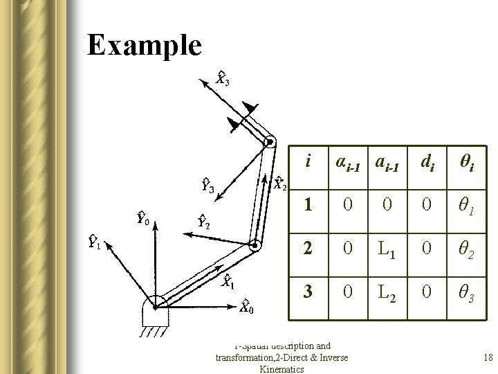
Example i αi-1 ai-1 di θi 1 0 0 0 θ 1 2 0 L 1 0 θ 2 3 0 L 2 0 θ 3 1 -Spatial description and transformation, 2 -Direct & Inverse Kinematics 18
Direct & Inverse Kinematics l Spatial description and transformation l Direct kinematics – Link description – Link-connection description – Affixing frames to links – Manipulator kinematics – Example l Inverse kinematics 1 -Spatial description and transformation, 2 -Direct & Inverse Kinematics 19
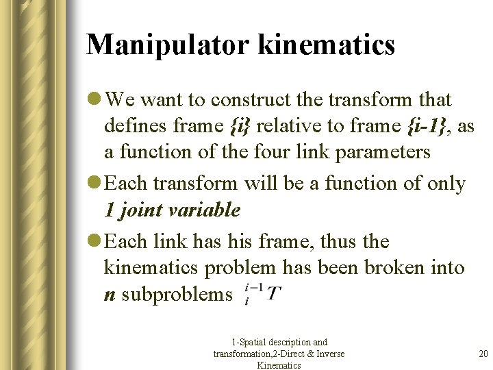
Manipulator kinematics l We want to construct the transform that defines frame {i} relative to frame {i-1}, as a function of the four link parameters l Each transform will be a function of only 1 joint variable l Each link has his frame, thus the kinematics problem has been broken into n subproblems 1 -Spatial description and transformation, 2 -Direct & Inverse Kinematics 20
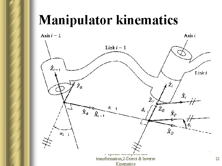
Manipulator kinematics 1 -Spatial description and transformation, 2 -Direct & Inverse Kinematics 21
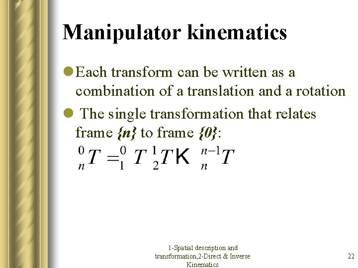
Manipulator kinematics l Each transform can be written as a combination of a translation and a rotation l The single transformation that relates frame {n} to frame {0}: 1 -Spatial description and transformation, 2 -Direct & Inverse Kinematics 22
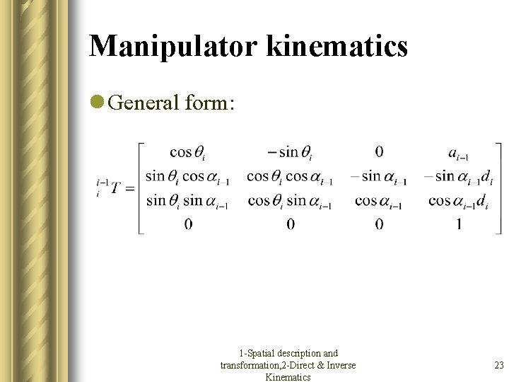
Manipulator kinematics l General form: 1 -Spatial description and transformation, 2 -Direct & Inverse Kinematics 23
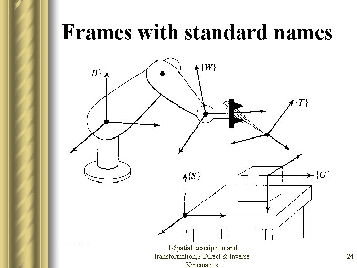
Frames with standard names 1 -Spatial description and transformation, 2 -Direct & Inverse Kinematics 24
Direct & Inverse Kinematics l Spatial description and transformation l Direct kinematics – Link description – Link-connection description – Affixing frames to links – Manipulator kinematics – Example l Inverse kinematics 1 -Spatial description and transformation, 2 -Direct & Inverse Kinematics 25
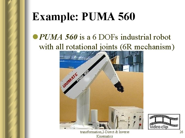
Example: PUMA 560 l PUMA 560 is a 6 DOFs industrial robot with all rotational joints (6 R mechanism) 1 -Spatial description and transformation, 2 -Direct & Inverse Kinematics 26
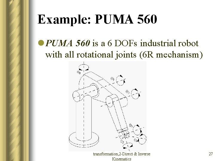
Example: PUMA 560 l PUMA 560 is a 6 DOFs industrial robot with all rotational joints (6 R mechanism) 1 -Spatial description and transformation, 2 -Direct & Inverse Kinematics 27
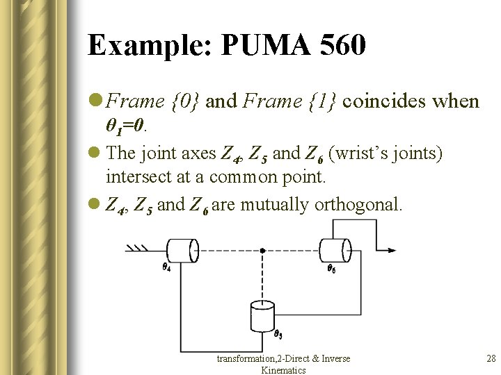
Example: PUMA 560 l Frame {0} and Frame {1} coincides when θ 1=0. l The joint axes Z 4, Z 5 and Z 6 (wrist’s joints) intersect at a common point. l Z 4, Z 5 and Z 6 are mutually orthogonal. 1 -Spatial description and transformation, 2 -Direct & Inverse Kinematics 28
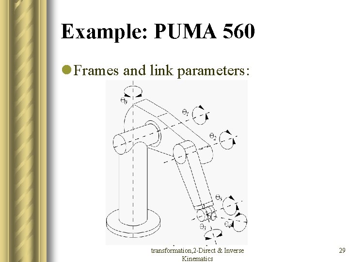
Example: PUMA 560 l Frames and link parameters: 1 -Spatial description and transformation, 2 -Direct & Inverse Kinematics 29
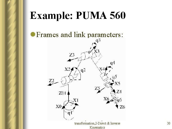
Example: PUMA 560 l Frames and link parameters: 1 -Spatial description and transformation, 2 -Direct & Inverse Kinematics 30
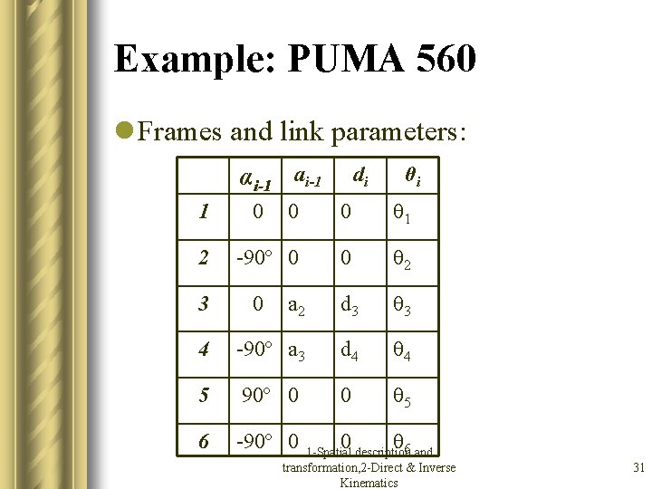
Example: PUMA 560 l Frames and link parameters: αi-1 ai-1 1 θi 0 0 θ 1 -90º 0 0 θ 2 a 2 d 3 θ 3 4 -90º a 3 d 4 θ 4 5 90º 0 0 θ 5 6 -90º 0 0 θ 2 3 0 di 0 6 and 1 -Spatial description transformation, 2 -Direct & Inverse Kinematics 31
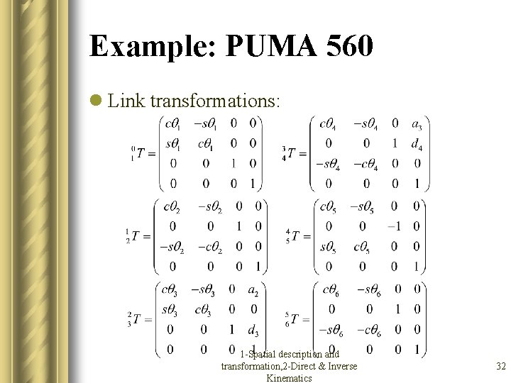
Example: PUMA 560 l Link transformations: 1 -Spatial description and transformation, 2 -Direct & Inverse Kinematics 32
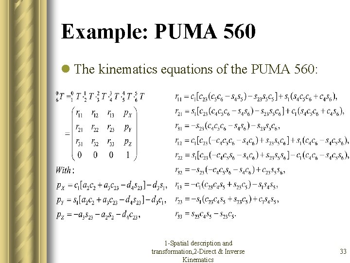
Example: PUMA 560 l The kinematics equations of the PUMA 560: 1 -Spatial description and transformation, 2 -Direct & Inverse Kinematics 33
Direct & Inverse Kinematics l Spatial description and transformation l Direct kinematics l Inverse kinematics – About the problem – Method of solution – Example 1 -Spatial description and transformation, 2 -Direct & Inverse Kinematics 34
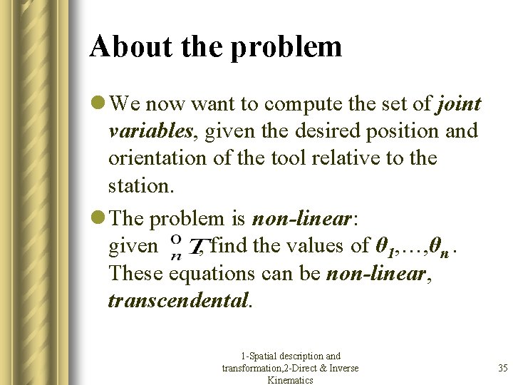
About the problem l We now want to compute the set of joint variables, given the desired position and orientation of the tool relative to the station. l The problem is non-linear: given , find the values of θ 1, …, θn. These equations can be non-linear, transcendental. 1 -Spatial description and transformation, 2 -Direct & Inverse Kinematics 35
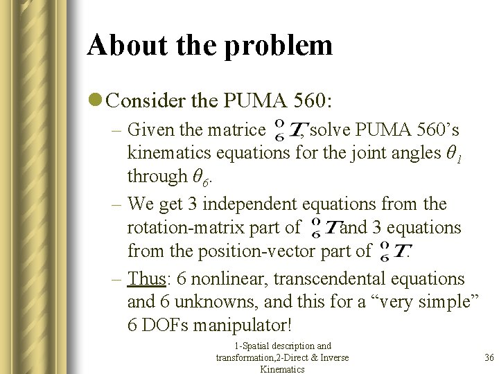
About the problem l Consider the PUMA 560: – Given the matrice , solve PUMA 560’s kinematics equations for the joint angles θ 1 through θ 6. – We get 3 independent equations from the rotation-matrix part of and 3 equations from the position-vector part of. – Thus: 6 nonlinear, transcendental equations and 6 unknowns, and this for a “very simple” 6 DOFs manipulator! 1 -Spatial description and transformation, 2 -Direct & Inverse Kinematics 36
About the problem l We must ask the following questions: – Is there a solution? – Are there several solutions? – How to solve the problem? 1 -Spatial description and transformation, 2 -Direct & Inverse Kinematics 37
Workspace l If the goal (desired position and orientation) is in the reachable workspace, then there’s at least 1 solution. l The reachable workspace is dependent on the manipulator. l There might be several solutions. l We won’t cover the following considerations: obstacles, limits on joint ranges, . . . 1 -Spatial description and transformation, 2 -Direct & Inverse Kinematics 38
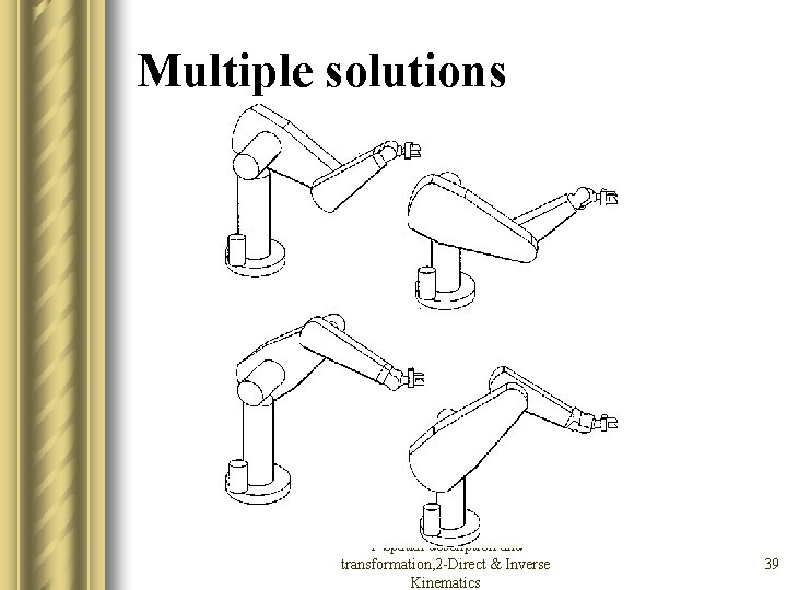
Multiple solutions 1 -Spatial description and transformation, 2 -Direct & Inverse Kinematics 39
Thank you 1 -Spatial description and transformation, 2 -Direct & Inverse Kinematics 40
- Slides: 40