2 5 2 Bridge FullWave Rectifier Operation Bridge

2. 5. 2 Bridge Full-Wave Rectifier Operation

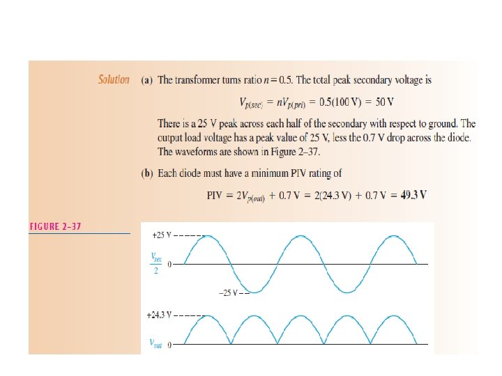
Bridge Output Voltage Neglecting the diode drops If these diode drops are taken into account, the output voltage is

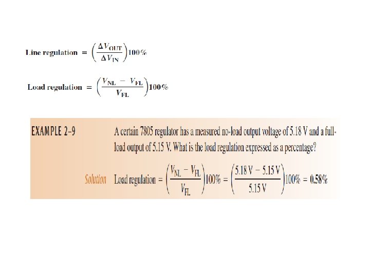
Percent Regulation The regulation expressed as a percentage is a • figure of merit used to specify the performance of a voltage regulator. It can be in terms of input (line) regulation or load regulation. The line regulation specifies how much change • occurs in the output voltage for a given change in the input voltage. The load regulation specifies how much change • occurs in the output voltage over a certain range of load current values, usually from minimum current (no load, NL) to maximum current (full load, FL).
 shows a diode positive limiter")
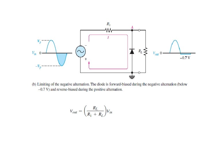
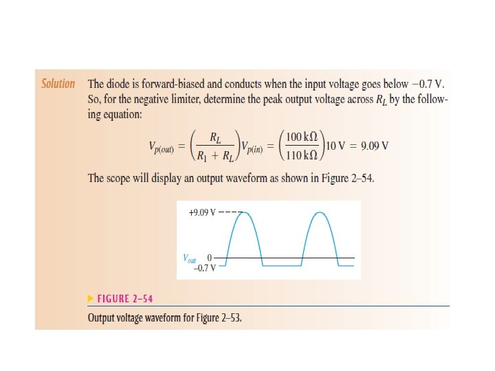
2– 7 DIODE LIMITERS AND CLAMPERS Figure 2– 52(a) shows a diode positive limiter • (also called clipper) that limits or clips the positive part of the input voltage.
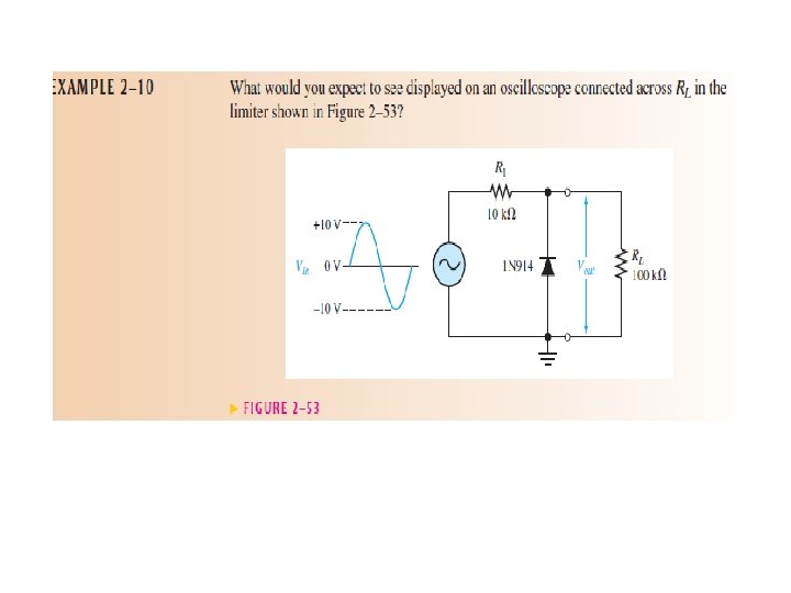

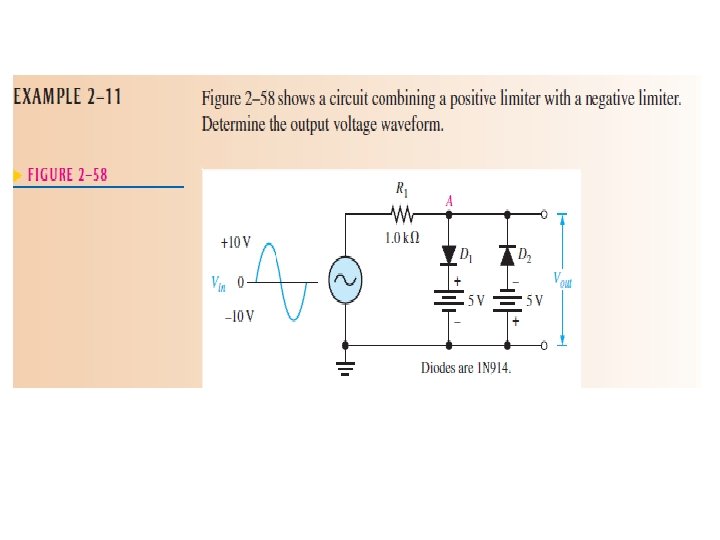
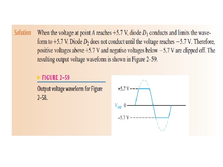
Biased Limiters The level to which an ac voltage is limited can be • adjusted by adding a bias voltage, VBIAS, in series with the diode.

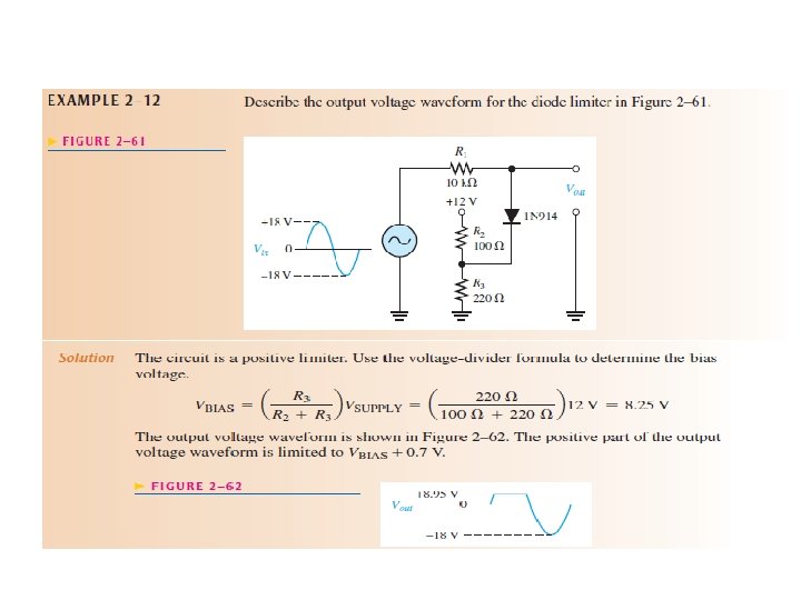
Voltage-Divider Bias The bias voltage is set by the resistor values • according to the voltage-divider formula.

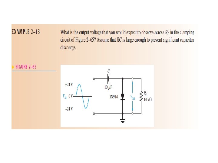
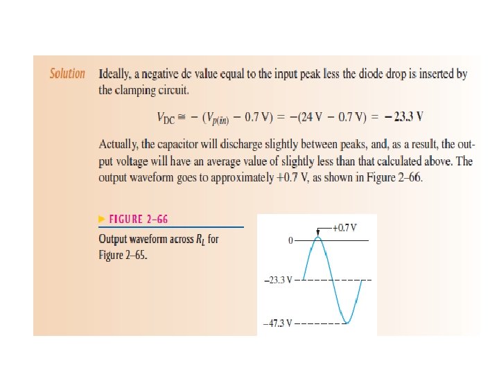
Diode Clampers A clamper adds a dc level to an ac voltage. • Clampers are sometimes known as dc restorers.

Positive clamper operation

Negative clamper

2– 8 VOLTAGE MULTIPLIERS Half-Wave Voltage Doubler A voltage doubler • is a voltage multiplier with a multiplication factor of two.

Half-wave voltage doubler operation. Vp is the peak secondary voltage.

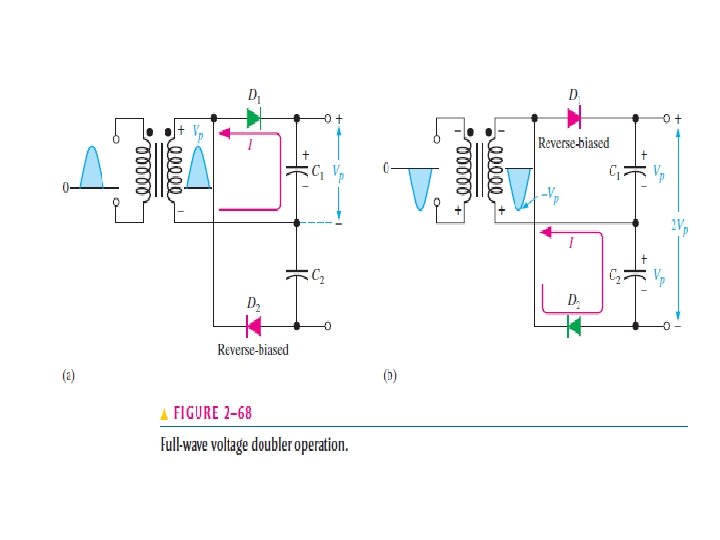
Full-Wave Voltage Doubler A full-wave doubler is shown in Figure 2– 68. • When the secondary voltage is positive, D 1 is forward-biased and C 1 charges to approximately Vp, as shown in part (a). During the negative half-cycle, D 2 is forward-biased and C 2 charges to approximately Vp, as shown in part (b). The output voltage, 2 Vp, is taken across the two capacitors in series.

- Slides: 24