2 1 Amplitude Modulation Full AM Mathematical representation
")


 amplitude modulated wave Frequency spectrum: fc-fm Bandwidth=fm(max) fc")
 Frequency spectrum: fc-fm fc fc+fm Bandwidth=fm(max) Total Power=+Pusb")


 � The modulating signal only changes the phase of")


- Slides: 30
2. 1 Amplitude Modulation (Full AM)
Mathematical representation for AM Modulation 1 The carrier signal is 2 In the same way, a modulating signal (information signal) can also be expressed as 3 The amplitude-modulated wave can be expressed as
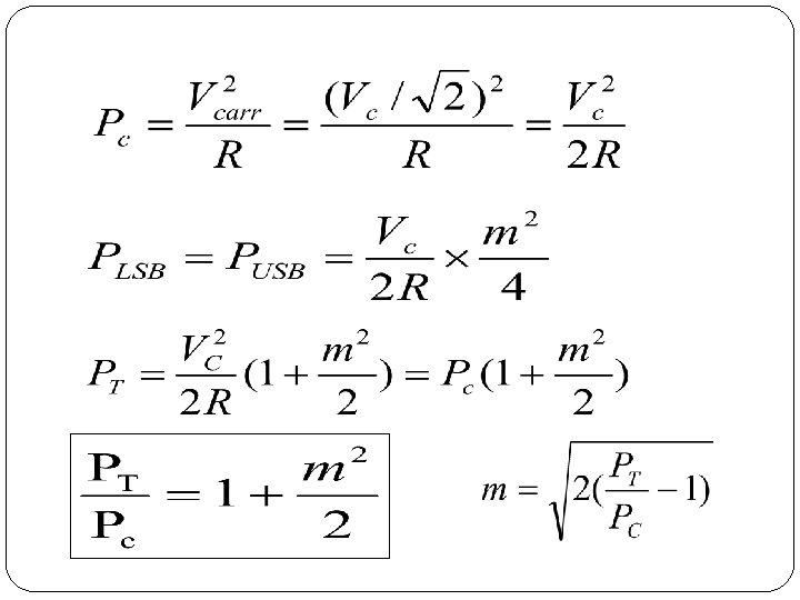
4 By substitution 5 The modulation index. 6 Therefore The full AM signal may be written as
Frequency Spectrum of the AM signal fc-fm f. C fc+fm 2 fm fc-fm fc fc+fm
The frequency spectrum of AM waveform contains three parts: 1. A component at the carrier frequency fc 2. An upper side band (USB), whose highest frequency component is at fc+fm 3. A lower side band (LSB), whose highest frequency component is at fc-fm • The bandwidth of the modulated waveform is twice the information signal bandwidth. Because of the two side bands in the frequency spectrum its often called Double Sideband with Large Carrier. (DSB-LC) • The information in the base band (information) signal is duplicated in the LSB and USB and the carrier conveys no information.
2. 2 Single Side Band (SSB) amplitude modulated wave Frequency spectrum: fc-fm Bandwidth=fm(max) fc fc+fm Total Power=Pcarrier +Pusb � A form of amplitude modulation in which the carrier is transmitted at full power but only one of the sidebands (either the upper or lower) is transmitted � Requires less bandwidth than DSBFC but also produces a demodulated signal with a lower amplitude
Single Side band Suppress Carrier (SSB-SC) Frequency spectrum: fc-fm fc fc+fm Bandwidth=fm(max) Total Power=+Pusb � A form of amplitude modulation in which the carrier is totally suppressed and one of the sidebands removed. � Therefore, SSBSC requires half as much bandwidth as conventional DSB AM and considerably less transmitted power
Comparison of time domain representation of three common AM transmission systems
2. 3 Modulation index and Signal power DCTC, By Ya Bao
2. 5 AM using square law modulator circuit
2. 6 Frequency Modulation Carrier wave Baseband signal Small amplitude: low frequency Large amplitude: high frequency Modulated wave Frequency varyingamplitude constant
� Mathematical analysis: Let message signal: And carrier signal: During the process of frequency modulations the frequency of carrier signal is changed in accordance with the instantaneous amplitude of message signal. Therefore the frequency of carrier after modulation is written as To find the instantaneous phase angle of modulated signal, integrate equation above w. r. t. t
Thus, we get the FM wave as: Where modulation index for FM is given by
Modulation Index. All FM transmissions are governed by a modulation index, , which controls the dynamic range of the information being carried in the transmission. The modulation index, , is the ratio of the frequency deviation, fc , to the maximum information frequency, fi , as shown below: Bandwidth of FM FM radio uses a modulation index, > 1, and this is called wideband FM. As its name suggests the bandwidth is much larger than AM. In national radio broadcasts using FM, the frequency deviation of the carrier fc , is chosen to be 75 k. Hz, and the information baseband is the high fidelity range 20 Hz to 15 k. Hz.
Thus the modulation index, is 5 (i. e. 75 k. Hz � 15 k. Hz), and such s broadcast requires an FM signal bandwidth given by: If < 1, then the spectrum looks like this:
2. 7 Phase Modulation (PM) � The modulating signal only changes the phase of the carrier signal. � The phase change manifests itself as a frequency change but the instantaneous frequency change is proportional to the derivative of the amplitude. � The bandwidth is higher than for AM.
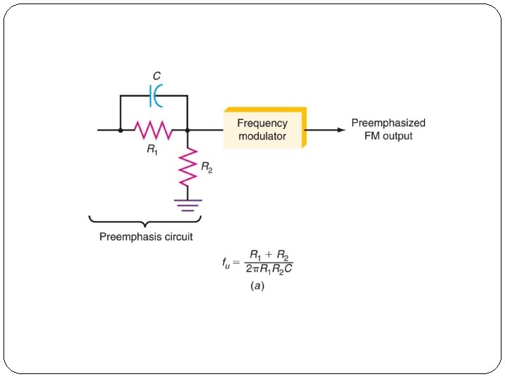
2. 8 Pre emphasis and De emphasis circuit Pre emphasis �Noise can interfere with an FM signal and particularly with the high-frequency components of the modulating signal. �Noise is primarily sharp spikes of energy and contains a lot of harmonics and other high-frequency components. �To overcome high-frequency noise, a technique known as pre emphasis is used. �A simple high-pass filter can serve as a transmitter’s preemphasis circuit. �Pre-emphasis provides more amplification of only highfrequency components.
De emphasis �A simple low-pass filter can operate as a de emphasis circuit in a receiver. �A de emphasis circuit returns the frequency response to its normal flat level. �The combined effect of pre emphasis and de emphasis is to increase the signal-to-noise ratio for the high-frequency components during transmission so that they will be stronger and not masked by noise.
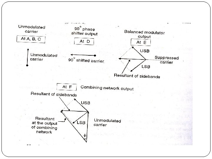
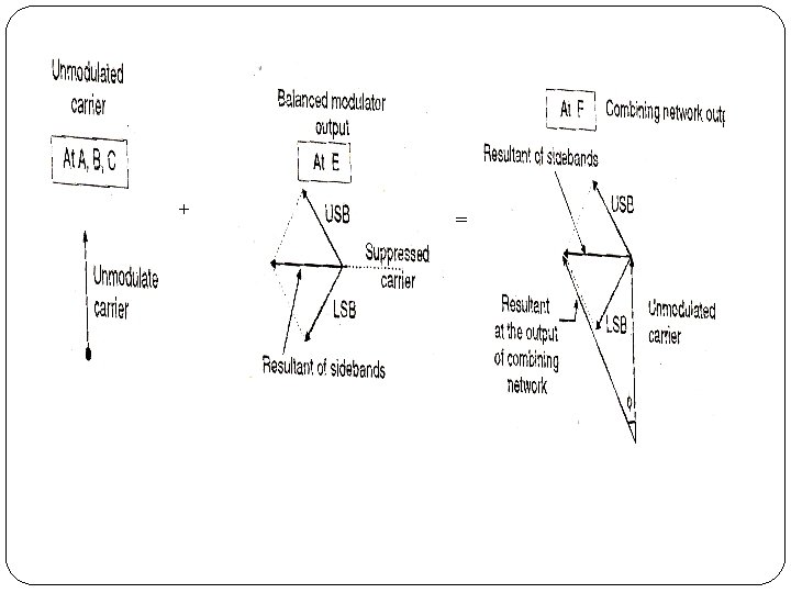
2. 9 Generation technique for FM waves üDirect Method: when the frequency of carrier is modulated by information signal üIndirect Method: when the phase of carrier is modulated by information signal 1. Varactor diode modulator( Direct method) 2. Reactance modulator( Direct method) 3. Armstrong method (Indirect method)
Varactor Diode FM modulator
CIRCUIT DIAGRAM OF VARACTOR DIODE MODULATOR
FET REACTANCE MODULATOR .
Modulating signal Career Frequency modulation Phase modulation
INDIRECT FM GENERATION Integrator