185 496 Mechanical System Design III Condenser Design


: 5. Determine the steam-side convective heat transfer coefficient,")


 Recalculate water velocity, V")


- Slides: 40
185 496 Mechanical System Design III Condenser Design By Assoc. Prof. Sommai Priprem, Ph. D. Department of Mechanical Engineering Khon Kaen University Reference: Suryanarayana N. V. , and Arici Oner, Design and Simulation of Thermal System, International Edition 2004, Mc. Graw-Hill.
Condenser �Condensers are used in a large number of systems; a condenser is an essential component of steam power plants and refrigeration plants. Condensers are also used in chemical plants and other situations. �Having identified a condenser for a component design, we design a condenser for a small power plant. The condenser is to be designed for a steam turbine. The information about the turbine is available in Table 8. 1.
Table 8. 1 Steam Turbine output 1000 k. W Steam pressure at inlet to turbine 2000 k. Pa Steam temperature at inlet 400 °C Exit pressure 10 k. Pa Efficiency of turbine 0. 8 Temperature of available cooling water 25 °C Temperature of ambient air 40 °C
Steam Power Plant with Feedwater Heater 1 Turbine wt Boiler 2 3 QB Feedwater Heater Cooling Water Pump 7 5 Feedwater Pump Qc Condenser 4 6 Open type feedwater heater รศ. ดร. สมหมาย ปรเปรม
Steam Condenser: 2 2 -importants functions 1. to condense exhaust steam recover the high-quality feedwater (reduce cost) 2. to create low back pressure (vacuum) of the turbine. more turbine work higher efficiency Condenser Cooling Water T P 1 P 2 3 2 s 5 รศ. ดร. สมหมาย ปรเปรม
8. 7. 1 Develop Preliminary Specifications and Constraints Assume that the required amount of cooling water is available if we choose a water-cooled condenser. We will require that the condenser should 1. Be easy to maintain and repair 2. Conform to applicable practices 3. Be such that the temperature rise of the cooling water should not exceed about 7 o. C to conform to current practice.
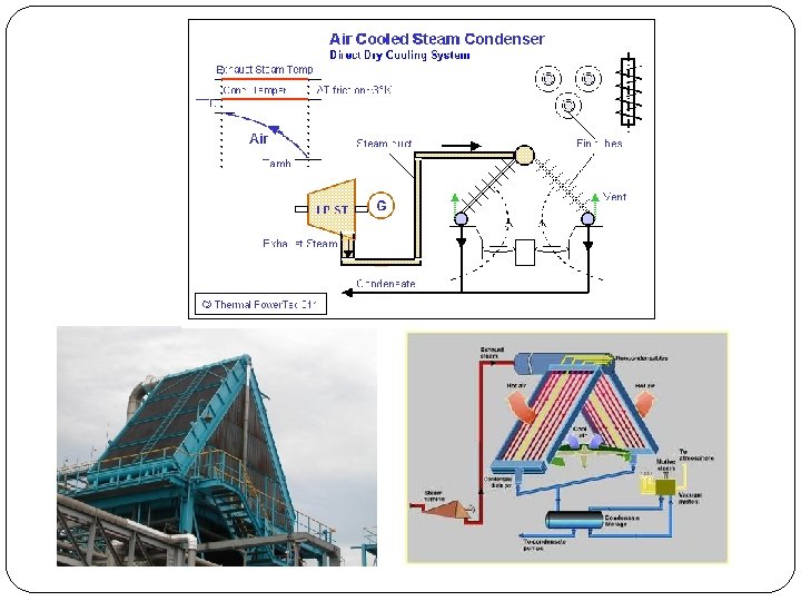
8. 7. 2 Develop Detailed Specifications and Concept 1. Assume feedwater leaves the condenser at a temperature slightly below the temperature corresponding to the saturation temperature at the exit pressure of l 0 k. Pa. 2. The two types of condensers to be considered are the water-cooled condenser and the air-cooled condenser. Water-cooled condensers are generally of the shell-and-tube type, either one-tube pass or two-tube pass. Air-cooled condensers are generally of the crossflow type with plates attached to the tubes acting as extended surfaces. 3. The current practice is to limit the water velocity in tubes to a maximum of about 2. 5 m/s and air velocity for aircooled condensers to about 10 m/s.
Design Alternatives Table 8. 2 Comparative merits of water-cooled and air-cooled condensers Feature Air-cooled Water-Cooled Cost + Weight + Volume + Noise + Source-air or water Available Repair + Reliability + +
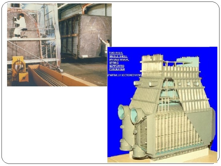
Surface Steam Condenser • Most common used in powerplants. • It is shell-and-tube type heat exchanger. • Size up to 1 million ft 2 (93, 000 m 2) heat transfer area. Steam inlet Discharge water outlet Condenser Shell Water Box Tubes Air-Vapor outlet Water Box Condensate outlet 11 รศ. ดร. สมหมาย ปรเปรม Cold Water inlet
2 -Pass Steam Condenser Steam inlet Discharge water outlet Condenser Shell Air-Vapor outlet Water Box Condensate outlet 12 รศ. ดร. สมหมาย ปรเปรม Cold Water inlet
• The two-tube pass condenser is slightly more complicated, as both the water inlet and exit are at the same end. But it is easier to maintain and repair. It is likely to lead to a smaller length. Choose the twotube pass condenser
Temperature variation in fluids T Steam T 2 LMTD TTD er Wat ITD TR T 1 L ITD = Internal Temperature Difference TTD = Terminal Temperature Difference TR = Temperature rise LMTD = Log Mean Temperature Difference ��. ������� 14
8. 7. 3 Detailed Design Further specifications are as follows: 1. The condenser may be either rectangular or circular (including oval). The choice is somewhat arbitrary. Choose a rectangular condenser. 2. Length should be between 1 to 3 times the width. 3. As already indicated, water velocity is limited to a maximum of 2. 5 m/s. Preferred velocity is 2 m/s.
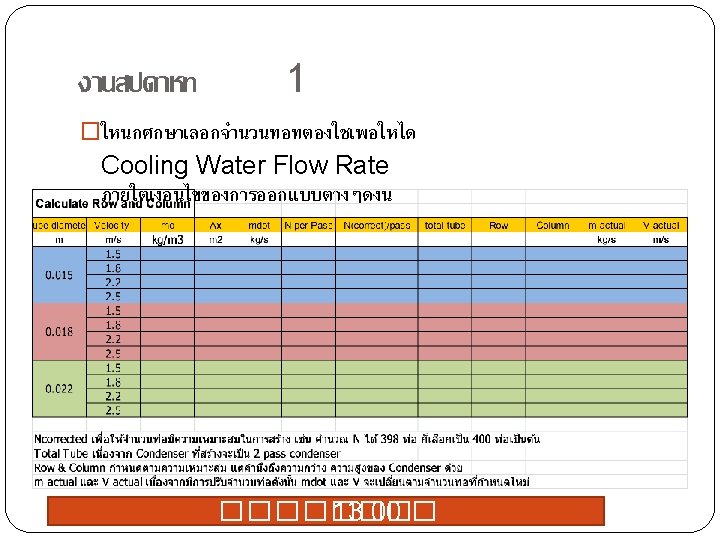
Steps involved in the design are: 1. Estimate the heat transfer rate. 2. Determine the cooling water flow rate. 3. For different velocities of the cooling water and diameter of tubes, find the length of the tubes. (3 -tube dia. x 4 velocity for each tube size) 4. Compute the pumping power in each case. 5. Choose the most desirable combination of the sizes of the condenser and pumping power.
�There a number of combinations of the design that will satisfy the heat transfer requirement. A parametric study will be performed so that one or more appropriate designs can be identified. The steps in the design are: 1. Assume a tube diameter. 2. Assume a water velocity between, say, 1. 5 m/s and 2. 5 m/s. 3. Determine the number of tubes in each pass to yield the required mass rate of flow of water.
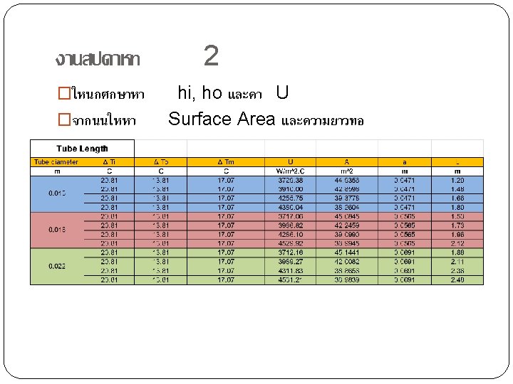
�The steps in the design (continue): 5. Determine the steam-side convective heat transfer coefficient, ho. The condensation heat transfer coefficient requires the tube surface temperature, which is not known. It is determined by iteration. 6. Determine the overall heat transfer coefficient, U. 7. Determine the surface area, and length of the tubes from Equation 6. 130
Isentropic Efficiency of Turbines T Turbine w T 1 P 1 Isentropic Process 1 Actual Process P 2 T 2 s 2 s s 1=s 2 s s 2 s
2 Condenser Heat Load Condenser Cooling Water q Cooling Water Steam P 1 2 q ��. ������� 20
L
No of tube calculated Selected no. of tube (round number) Recalculate water velocity, V (because no. of tube changed) Design configuration: Select no. of Row x no. of Column = no. tube Select tube arrangement: In line or Stagger
� Method proposed by the Heat Exchange Institute Standards for Steam Surface Condenser: Q = UA ΔTm where: Q U A = heat load on condenser, = overall condenser heat-transfer coefficient, based on outside tube area, = total out side tube surface area, ΔTm = log mean temperature difference in the condenser: ΔTm = (ΔTi – ΔTo)/ln(ΔTi /ΔTo)
filmwise condensation on horizontal cylinder Ts Unknown assume Ts first qi Tw, avg Ts hi
filmwise condensation on horizontal cylinder Ts ho Tfilm, avg Tsat
filmwise condensation on horizontal cylinder Ts qo Tsat ho Tfilm, avg
condensation. Film thickness developed thicker on the lower tube row causes lower heat transfer coefficient. Table 6. 4 Values of h. N/h ………………. For. N> 14, h. N/h = 1/Nl/4
Itteration for average wall temperature T Steam Ts Wall er Wat L
Ts ho hi Tsat Tw Ts, new Check Qsteam Qwater Error 25. 0 Assume 33. 8 34. 6 ho =f(Ts) 50. 0 67. 7 69. 2 69. 3 Calculated 80 80 80 fixed 40 40 40 fixed 30 30 30 (ho. Tsat+hi. Tw)/(ho+hi) 33. 34. 34. 8 6 6 34. 6 6 6 ho(Tsat-Ts) hi(Ts-Tw) Qsteam - Qwater 750 400 - 1, 150 Qwater = Qsteam hi(Ts-Tw) = ho(Tsat-Ts) hi. Ts - hi. Tw = ho. Tsat - ho. Ts hi. Ts + ho. Ts = ho. Tsat +hi. Tw Ts(hi+ho) = ho. Tsat +hi. Tw Ts= (ho. Tsat +hi. Tw)/(hi+ho) 1 09 417 308 375 367 8 372 371 1 0. 0 412 371 Old style Iteration table 371 0. 0030
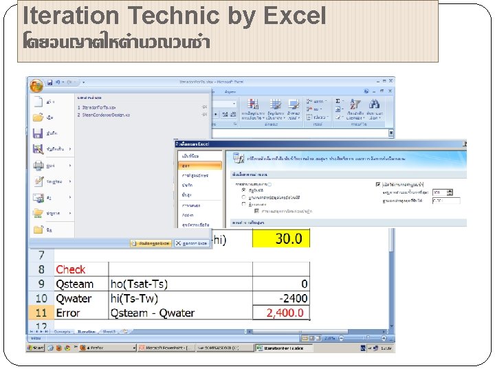
Iteration Technique by Excel ���������� Ts ho hi Tsat Tw Assume Ts*2 Calculated fixed 34. 6 Ts, new Check Qsteam Qwater Error (ho. Tsat+hi. Tw)/(ho+hi) 34. 6 ho(Tsat-Ts) hi(Ts-Tw) Qsteam - Qwater 371 0. 00000 69. 3 80 40 30
L
Pumping Power �Pressure drops ΔPtotal = ΔPtubes + ΔPWater Box
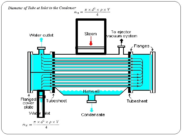
water boxes the condenser should include water box at either end a suitable plate at the top to prevent the impingement of the high-speed exhaust steam (with water droplets) on the tubes. These will make the overall dimensions significantly higher than the tube bank dimensions. Diameter of Tube at Inlet to the Condenser The diameter of the tube depends on the velocity of the steam at inlet. A steam inlet velocity of 30 to 60 m/s is suggested in Fraas (1989).
Week 1 Assignment: Condenser design concept. 1. Write Design Specifications and Design Criterias. 2. Develop an Excel calculation sheet of 1 design case. • สงในชวโมง Design specifications + Heat Load Calculation • การบาน For the selected tube diameter and the water velocity calculate the heat transfer surface area and the pumping power. 3. Upload the file on your group website. Hint 1. Use Excel x-steam. 2. For complex equation, create User Defined Function. 3. Use a calculated data series in the TEXT for this assignment.
Week 2 Assignment: Paramatic study. 1. Vary 3 size of tube diameter and 4 values of water velocity then calculate for heat transfer surface area and pumping power corresponding to each input. 2. Show tabulate results and also show the results with a single graph. 3. Discuss the results and choose your best design. 4. Conclude your condenser configuration and make detail drawing. 5. Upload the file on your group website.