18 447 Computer Architecture Lecture 7 Microprogrammed Microarchitectures


, at the end of")

 implementation first,")


 only as much")


 State 33 (100001) State 35 (100011) State")


- Slides: 43
18 -447 Computer Architecture Lecture 7: Microprogrammed Microarchitectures Prof. Onur Mutlu Carnegie Mellon University Spring 2013, 1/30/2013
Homework 2 n Homework 2 out q q q Due February 11 LC-3 b microcode ISA concepts, ISA vs. microarchitecture, microcoded machines 2
Reminder: Lab Assignment 1 n Due this Friday (Feb 1), at the end of Friday lab A functional C-level simulator for a subset of the MIPS ISA n Study the MIPS ISA Tutorial n Go to the Lab Sessions, especially if you need help n 3
Lookahead: Lab Assignment 2 n Lab Assignment 1. 5 q q n Verilog practice Not to be turned in Lab Assignment 2 q q Due Feb 15 Single-cycle MIPS implementation in Verilog All labs are individual assignments No collaboration; please respect the honor code 4
Lookahead: Extra Credit for Lab Assignment 2 n Complete your normal (single-cycle) implementation first, and n n n get it checked off in lab. Then, implement the MIPS core using a microcoded approach similar to what we will discuss in class. We are not specifying any particular details of the microcode format or the microarchitecture; you can be creative. For the extra credit, the microcoded implementation should execute the same programs that your ordinary implementation does, and you should demo it by the normal lab deadline. You will get partial credit for the extra credit Document what you have done and demonstrate well 5
Readings for Next Lecture n Pipelining q n P&H Chapter 4. 5 -4. 8 Pipelined LC-3 b Microarchitecture q http: //www. ece. cmu. edu/~ece 447/s 13/lib/exe/fetch. php? medi a=18447 -lc 3 b-pipelining. pdf 6
Today’s Agenda n Finish the Microprogrammed LC-3 b Design n Do some microprogramming n Start pipelining 7
Review: Last Lecture n n Finished single-cycle microarchitectures Microarchitecture design principles Basic performance evaluation (execution time equation) What does it mean to design for the common case (or bread and butter design)? q n n If memory takes 90% of execution time … How does the single cycle microarchitecture make “critical path design” difficult? Remember the performance equation that consists of three components… How can you improve each component in a multi-cycle microarchitecture? 8
Review: Microarchitecture Design Principles n Critical path design q n Find the maximum combinational logic delay and decrease it Bread and butter (common case) design q Spend time and resources on where it matters n q n i. e. , improve what the machine is really designed to do Common case vs. uncommon case Balanced design q q Balance instruction/data flow through hardware components Balance the hardware needed to accomplish the work 9
Review: Multi-Cycle Microarchitectures n Goal: Let each instruction take (close to) only as much time it really needs n Idea q q Determine clock cycle time independently of instruction processing time Each instruction takes as many clock cycles as it needs to take n n Multiple state transitions per instruction The states followed by each instruction is different 10
Quick Review: A Microprogrammed Multi-Cycle Microarchitecture 11
Review: The Instruction Processing Cycle q q q Fetch Decode Evaluate Address Fetch Operands Execute Store Result 12
Review: A Basic Multi-Cycle Microarchitecture n Instruction processing cycle divided into “states” n n A stage in the instruction processing cycle can take multiple states A multi-cycle microarchitecture sequences from state to process an instruction n The behavior of the machine in a state is completely determined by control signals in that state n The behavior of the entire processor is specified fully by a n In a state (clock cycle), control signals control finite state machine n n How the datapath should process the data How to generate the control signals for the next clock cycle 13
Review: Microprogrammed Control Terminology n Control signals associated with the current state q n Act of transitioning from one state to another q q n Determining the next state and the microinstruction for the next state Microsequencing Control stores control signals for every possible state q n Microinstruction Store for microinstructions for the entire FSM Microsequencer determines which set of control signals will be used in the next clock cycle (i. e. next state) 14
Review: A Simple LC-3 b Control and Datapath 15
Review: An LC-3 b State Machine n n n Patt and Patel, App C, Figure C. 2 Each state must be uniquely specified q Done by means of state variables 31 distinct states in this LC-3 b state machine q n Encoded with 6 state variables Examples q q q State 18, 19 correspond to the beginning of the instruction processing cycle Fetch phase: state 18, 19 state 33 state 35 Decode phase: state 32 16
Review: LC-3 b State Machine: Some Questions n How many cycles does the fastest instruction take? n How many cycles does the slowest instruction take? n Why does the BR take as long as it takes in the FSM? n What determines the clock cycle? n Is this a Mealy machine or a Moore machine? 17
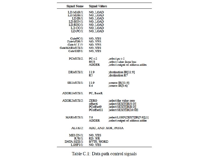
LC-3 b Datapath n Patt and Patel, App C, Figure C. 3 n Single-bus datapath design q q q n At any point only one value can be “gated” on the bus (i. e. , can be driving the bus) Advantage: Low hardware cost: one bus Disadvantage: Reduced concurrency – if instruction needs the bus twice for two different things, these need to happen in different states Control signals (26 of them) determine what happens in the datapath in one clock cycle q Patt and Patel, App C, Table C. 1 18
LC-3 b Datapath: Some Questions n How does instruction fetch happen in this datapath according to the state machine? n What is the difference between gating and loading? n Is this the smallest hardware you can design? 22
LC-3 b Microprogrammed Control Structure n Patt and Patel, App C, Figure C. 4 n Three components: q n n n Microinstruction: control signals that control the datapath (26 of them) and determine the next state (9 of them) Each microinstruction is stored in a unique location in the control store (a special memory structure) Unique location: address of the state corresponding to the microinstruction q n Microinstruction, control store, microsequencer Remember each state corresponds to one microinstruction Microsequencer determines the address of the next microinstruction (i. e. , next state) 23
LC-3 b Microsequencer n n n Patt and Patel, App C, Figure C. 5 The purpose of the microsequencer is to determine the address of the next microinstruction (i. e. , next state) Next address depends on 9 control signals 27
The Microsequencer: Some Questions n When is the IRD signal asserted? n What happens if an illegal instruction is decoded? n What are condition (COND) bits for? n How is variable latency memory handled? n How do you do the state encoding? q q q Minimize number of state variables Start with the 16 -way branch Then determine constraint tables and states dependent on COND 29
An Exercise in Microprogramming 30
Handouts n n n 7 pages of Microprogrammed LC-3 b design http: //www. ece. cmu. edu/~ece 447/s 13/doku. php? id=manu als http: //www. ece. cmu. edu/~ece 447/s 13/lib/exe/fetch. php? m edia=lc 3 b-figures. pdf 31
A Simple LC-3 b Control and Datapath 32
State Machine for LDW State 18 (010010) State 33 (100001) State 35 (100011) State 32 (100000) State 6 (000110) State 25 (011001) State 27 (011011) Microsequencer
End of the Exercise in Microprogramming 42
Homework 2 n You will write the microcode for the entire LC-3 b as specified in Appendix C 43