17 May 2006 1 ANISOTROPIC CONDUCTIVE FILM ACF


 Outline of ACF Structure and Function of ACF 2)")


 Sufficient")


 17 May 2006 15")


")
")
 To use insulated particle")


")
, ITO-Glass")
, ITO-Glass")
 Degree of curing ? Reaction Rate (FT-IR) Characteristics")

")


 17 May 2006 35 2. Chip on Glass Bonding 3. Flex on Glass")


 +")
 17 May 2006 43 <TEG>")


 17 May 2006 49 2. Chip on Glass Bonding 3. Flex on Glass")


Copyright 2006 Sony Chemicals Corporation. All Rights Reserved 17")

![17 May 2006 57 FT-IR; Fourier transform - Infrared Spectrometry 反応率 [%] 100 90](https://slidetodoc.com/presentation_image/33d8881c4e8d999c72d43334511d824d/image-57.jpg "17 May 2006 57 FT-IR; Fourier transform - Infrared Spectrometry 反応率 [%] 100 90")

![17 May 2006 59 DSC 反応率 [%] DSC: Differential Scanning Calorimetry, 100 90 80](https://slidetodoc.com/presentation_image/33d8881c4e8d999c72d43334511d824d/image-59.jpg "17 May 2006 59 DSC 反応率 [%] DSC: Differential Scanning Calorimetry, 100 90 80")
Copyright 2006 Sony Chemicals Corporation. All Rights")

- Slides: 61
17 May 2006 1 ANISOTROPIC CONDUCTIVE FILM ACF TECHNICAL INFORMATION Outline of ACF and Trend of COG ACF Sony Chemicals Corporation JISSO Material Div. Technology Development Dept. 本資料に記載されている特性等は当社の評価結果に基づいたものであり,ご使用における製品特性を保証するものではありません。 (C)Copyright 2006 Sony Chemicals Corporation. All Rights Reserved
Table of Contents 1. Outline of ACF Conductivity, Insulation, Adhesion and Reaction etc. . 2. Trend of COG ACF Road Map, COG Trend for Fine Pitch ACF technology for fine pitch Development map of COG ACF etc. . (C)Copyright 2006 Sony Chemicals Corporation. All Rights Reserved 17 May 2006 2
1. Outline of ACF 1) Outline of ACF Structure and Function of ACF 2) Basic Functions of ACF Conductivity Achievement of Conductivity Control of particle capture Particle Deformation Effect of cushion material Insulation Insulator Coating Particles Insulated Particle and Short Adhesion, Reaction Rate and Interfacial Adhesion, Cohesion ACF Curing Process Reaction of ACF Ref. ) Measuring method of reaction rate /FT-IR, DSC Elastic Modulus and Tg (C)Copyright 2006 Sony Chemicals Corporation. All Rights Reserved 17 May 2006 3
17 May 2006 4 Structure of ACF: Anisotropic Conductive Film Conductive material is dispersed in the adhesive film. Conductive Particle Binder (Thermoset resin) Ex. Epoxy resin (Insulator Coating) Au Ni Resin Φ 3~5μm Ex. Metal plated resin particle Conductive Particles (C)Copyright 2006 Sony Chemicals Corporation. All Rights Reserved
17 May 2006 5 ACF Process Outline Coating Dry Laminate Dryer Step 1: Material mixing Step 2: Coating Check Appearance Slitter Step 3: Slitting Step 4: Rewinding & Check (C)Copyright 2006 Sony Chemicals Corporation. All Rights Reserved Step 5: Packing
17 May 2006 6 Structure of ACF / Product Form Surface Treatment Cover film (Transparent, t=12, 25μm) Double Type ACF Surface Treatment Base film (White or Translucent, t=38, 50, 75μm) Single Type ACF Base film (White or Translucent, t=38, 50, 75μm) Surface Treatment (C)Copyright 2006 Sony Chemicals Corporation. All Rights Reserved
Function of ACF and Parameter of ACF bonding 17 May 2006 7 Basic Functions of ACF is a functional adhesive tape which is able to connect (conductivity, adhesion, insulation) multi-terminals in one time. Conductivity Step-1 ACF selection to match bonding materials Step-2 Decision to optimize bonding condition Insulation Adhesion Temperature, Pressure, Time Parameter of ACF Bonding Glass (Panel) Chip ACF (C)Copyright 2006 Sony Chemicals Corporation. All Rights Reserved
17 May 2006 8 Examples of ACF application COG: Chip on Glass FOG: Flex on Glass COF: Chip on Flex FOF: Flex on Flex (replacement of connector,FPC-C/D) (C)Copyright 2006 Sony Chemicals Corporation. All Rights Reserved
Comparison between COG and FOG ACF Item Conductivity ACF for COG ○: Minimum Contact Area ◎: Minimum Contact Area 13 um× 100 um=1300 um 2 Finepitch 13 um× 0. 8 mm=10400 um 2 Insulation ○: Minimum Conductor Space 20μm ◎: Minimum Conductor Space 12μm Finepitch Adhesion ◎:FPC/Panel, compatibility for all FPC type ○:IC/Panel Corrosion proof ○ ◎:High Reliability Low Temp. Short Time ◎:Short Tact,Productivity up ○: Warpage Stress Required Characteristics ACF Structure ACF Features ACF for FOG 17 May 2006 9 Single Layer 2 layer (ACF/NCF) Particle 4~ 10μm / Ni/Au coated Resin particle 3~ 4μm/ Ni/Au coated Resin particle Insulated Particle No (Partly Coated) Insulator coated Particle density Low:~ 0. 5 million/mm 3 High:~ 6 million/mm 3(ACF layer) Cured ACF Hardness Relatively soft:Tg=less than 130℃ Relatively hard:Tg=around 140~ 170℃ (C)Copyright 2006 Sony Chemicals Corporation. All Rights Reserved
17 May 2006 10 Basic Functions of ACF - Particle Deformation - Particle Capture Conductivity - Cohesion - Insulator coated particle - Particle Diameter / Density Reaction Insulation - Interfacial adhesion Adhesion (C)Copyright 2006 Sony Chemicals Corporation. All Rights Reserved
Basic Functions of ACF /Conductivity - Particle Deformation - Particle Capture Conductivity 1) Sufficient particles capture on a bump ⇒ Particle capture Reaction More than 3 particles are required. Statistics method is applied like ave. -3σ. Insulation Adhesion 2) Sufficient particle deformation ⇒ Bonding pressure Pay attention to Tool co-planarity, Bump Height deviation, Bump deformation (Short) (C)Copyright 2006 Sony Chemicals Corporation. All Rights Reserved 17 May 2006 11
17 May 2006 12 Achievement of Conductivity Plastic Core Ni/Au Plating Conductivity Bump Conductive Particle ITO Glass Pressure Conductivity shall be obtained through Ni/Au plating layer on a surface of particle. (C)Copyright 2006 Sony Chemicals Corporation. All Rights Reserved
Roles of Conductive Particle 17 May 2006 13 Particles absorb deviation of bump and trace height Particles keep the conductivity by their restitution when stress is applied High margin for bump and High Reliability trace height deviation (C)Copyright 2006 Sony Chemicals Corporation. All Rights Reserved
17 May 2006 14 Minimum particle Capture <TEG> ACF:CP 88 -series Glass:ITO-glass < Bonding Condition> 190℃40 MPa-5 s <Reliability condition> 85℃85%RH 1000 h - 初期値 - - 85℃85%RH-1000 h open good excellent ・ Conductivity is achieved in 1 particle on a bump. For consideration of reliability, more than 3 particle on a bump is required. ・ More than 5 particles on a bump achieves stable conductivity in reliability. (C)Copyright 2006 Sony Chemicals Corporation. All Rights Reserved
Control of particle capture (normal distribution and standard deviation σ) 17 May 2006 15 Excellent particle capture performance to apply 4. 5σ control. Probability less than Ave. -xσ Particle capture usually follows normal distribution. Probability Normal Distribution Ave. -xσ Ave. -4. 5σAve. -3σ Ave. -4. 5σ Ave. Particle Capture on a bump(pcs. ) Probability MORE THAN Ave. – x σ Probability LESS THAN Ave. – x σ 0. 99865 1350 ppm (0. 00135) 0. 9999966 3. 4 ppm (0. 0000034) The values above table are the probability of only lower side. (C)Copyright 2006 Sony Chemicals Corporation. All Rights Reserved
17 May 2006 16 Particle Deformation 20 MPa 40 MPa 60 MPa 100 MPa Pressure Too weak Good (C)Copyright 2006 Sony Chemicals Corporation. All Rights Reserved Too strong
Particle Deformation and Conductive Resistance Bump 17 May 2006 17 Deformed Bump ⇒ Bump Short Particle ITO Glass 6 MPa Maximum Conductive resistance after 1000 h[Ω] Pressure: 40 MPa 100 MPa 60 50 40 30 20 10 Aging 85℃85%R. H. 0 0 20 40 60 80 100 120 Bonding Pressure [MPa] Relationship between particle deformation and conductivity in reliability test (C)Copyright 2006 Sony Chemicals Corporation. All Rights Reserved
17 May 2006 18 Effect of cushion material <ACF> ACF for Fine Pitch(4μm Particle) Teflon <Bonding Condition> 190℃-40 MPa-5 sec Head is tilted on purpose when bonding <Teflon> None,50μm,80μm,100μm Heat Tool TEG-Glass TEG-IC ACF Stage Bump-B Bump-A <Bump/Particle Deformation> Teflon None 50μm 80μm ※ 100μm ※ Bump-A Bump-B ※:attention to temperature profile (next page) (C)Copyright 2006 Sony Chemicals Corporation. All Rights Reserved
17 May 2006 19 Effect of Cushion Material <ACF> ACF for Fine Pitch(4μm Particle) <Bonding Condition> 190℃-40 MPa-5 sec <Teflon> < Initial Conductive Resistance > Head is tilted on purpose when bonding None,50μm,80μm,100μm < Temperature Profile > None 50μm. T 80μm. T 100μm. T 190℃ 5 s 5 s To use cushion material, ・ Tool co-planarity tilt is released and particle deformation and conductive resistance is improved ・ However, temperature rise time becomes slow ⇒ Pay attention to reaction rate down (C)Copyright 2006 Sony Chemicals Corporation. All Rights Reserved
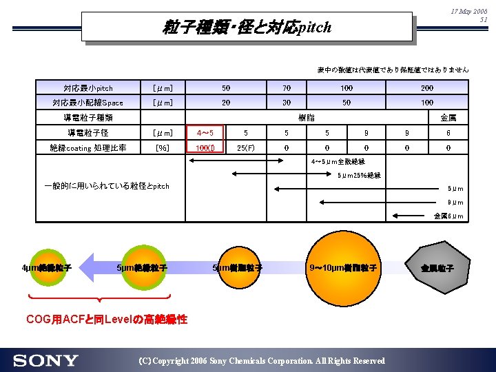
Basic Functions of ACF /Insulation 17 May 2006 20 1) To use insulated particle 2) To use small particle Conductivity 3) To decrease particle quantity - Insulator coated particle - Particle Diameter / Density (disadvantage to minute bump application) Insulated particle prevents short. Reaction Insulation As particle quantity is able to increase, Adhesion apply for minute bump (Fine Pitch) (C)Copyright 2006 Sony Chemicals Corporation. All Rights Reserved
17 May 2006 21 Insulator Coating Particles Insulator coating Normal Insulated Particle Ni/Au-Plating IC Bump Glass Short circuit occurs when the particles are jammed between bumps. Insulation is kept when the particles are jammed between bumps. (C)Copyright 2006 Sony Chemicals Corporation. All Rights Reserved
17 May 2006 22 Insulated Particle and Short Bump Space Bump ACF : CP 60 -series Bump Space : 15, 12. 5, 10μm Bump Height : 15μm Bonding Condition: 190℃-80 MPa-5 s N=16 set (10 point/set) Pattern 4μm Particle 4μm Insulated particle 3μm Insulated particle ・ Small diameter particle is able to apply narrow space. ・ Insulated particle realizes more narrow space. (C)Copyright 2006 Sony Chemicals Corporation. All Rights Reserved
Basic Functions of ACF /Adhesion, Reaction 17 May 2006 23 Conductivity - Cohesion Reaction Insulation - Interfacial adhesion Adhesion (C)Copyright 2006 Sony Chemicals Corporation. All Rights Reserved
Reaction Rate and Interfacial Adhesion, Cohesion 17 May 2006 24 1. Adhesion (interfacial adhesion) becomes higher to raise reaction rate. LSI ACF Pattern Interfacial adhesion between ACF and adhered material Substrate Material and surface condition (shape・contamination) influences on the adhesion. (Especially, Attention to type of FPC and contamination on glass) 2. ACF cohesion (hardness) becomes higher and conductive resistance becomes good to raise reaction rate. hold the particles repulsion Cohesion (≒Hardness) (C)Copyright 2006 Sony Chemicals Corporation. All Rights Reserved
Reaction Rate and Adhesion /FOG ACF:Developed ACF for FOG TEG: 2 layer FPC(CA-type), ITO-Glass Bonding condition: 140~ 200℃,3 MPa,5~ 10 sec Method: Y-peel, 50 mm/min Good Adhesion Cure the ACF sufficiently (Sufficient reaction rate) (C)Copyright 2006 Sony Chemicals Corporation. All Rights Reserved 17 May 2006 25
Reaction Rate and Conductivity /FOG ACF:Developed ACF for FOG TEG: 2 layer FPC(CA-type), ITO-Glass Bonding condition: 140~ 200℃,3 MPa,5~ 10 sec Good Conductivity (C)Copyright 2006 Sony Chemicals Corporation. All Rights Reserved 17 May 2006 26
Cohesion of ACF Reactivity Cohesion (Hardness) Degree of curing ? Reaction Rate (FT-IR) Characteristics of Cured ACF Hardness after curing ? Elastic Modulus Tg (Glass transition Temp. ) (C)Copyright 2006 Sony Chemicals Corporation. All Rights Reserved 17 May 2006 27
17 May 2006 28 Reaction of ACF < Reaction of Epoxy resin > Heat Epoxy resin O CH 2 CH CH 2 O + O Curing agents Anion/Cation CH CH 2 n O < Reference:Reaction of Acryl resin > Heat Acryl resin CH CH 2 + Curing agents CH CH 2 Radical (C)Copyright 2006 Sony Chemicals Corporation. All Rights Reserved n
Evaluation Example of ACF reaction 17 May 2006 29 - FT-IR - IR(Infrared Spectrometry) Analysis for ACF hardening reaction by measuring decrease of functional group Example of ACF Hardening Reaction CA Functional Group + CH 2 Functional Group ( Epoxy Group) CH 2 CA CH ~ O O Wave length After bonding ACF Equipment: BIORAD FTS 165 After bonding, Epoxy group decrease. Reaction Rate [%] Initial ACF CH 2 CH ~ OH Absorption (Epoxy Group) Wave length CH ~ 100 90 80 70 60 50 40 30 20 10 0 145 155 165 175 185 195 Bonding Temperature [℃] The peak height of Epoxy group also decrease. (C)Copyright 2006 Sony Chemicals Corporation. All Rights Reserved 205
Relationship between Elastic Modulus, Tg and Conductive Resistance 17 May 2006 30 Tg:Glass Transition Temperature Glass Region Rubber Region <Ref:Tg of various Plastic> Silicone Rubber :-125℃ Teflon :-110℃ PET : 67℃ poly vinyl acetate: 28~ 30℃ (chewing gum) Elastic Modulus (Hardness) Binder is hard and conductive resistance keeps good Binder is soft and conductive resistance increase Temperature High Tg (Hard)≒ Good conductive resistance in Reliability (C)Copyright 2006 Sony Chemicals Corporation. All Rights Reserved
Factors for Adhesion-1 : FPC Type 17 May 2006 31 The adhesion changes depending on the FPC type Adhesion surface:PI,Pattern Adhesion surface:ADH,Pattern Adhesion < 2 layer FPC 3 layer FPC ACF selection to meet the FPC type (C)Copyright 2006 Sony Chemicals Corporation. All Rights Reserved
Factors for Adhesion-2 : Surface Condition 17 May 2006 32 Surface Condition of 2 layer FPC Anchor Effect Adhesion Rough surface < Various Material In case low adhesion happens in the specific FPC, Please ask FPC maker and ACF maker (C)Copyright 2006 Sony Chemicals Corporation. All Rights Reserved
17 May 2006 33 ACF function and parameters Item Conductivity Insulation Adhesion Reactivity ◎ Temp. / time Bonding process Material IC Panel ◎ ◎ Temperature profile Reaction points ◎ △ - - Tool co-planality Particle deformation Bump deformation Fulidity ◎ ○ - - Melt viscosity Reactivity ◎ - ◎ ◎ Reaction rate Hardness ◎ - ○ Particle ◎ ◎ - - Particle Characteristics Particle diameter Bump size ◎ - - - Particle capture Bump space - ◎ - - Bump space Bump hardness ◎ △ - - Bump Hardness (HV) Bump height deviation ○ - - - Bump shape Contamination ○ - ◎ - Contact angle,Surface tension Pressure ACF - Control Points Tg (C)Copyright 2006 Sony Chemicals Corporation. All Rights Reserved
2. Trend of COG ACF - Road Map of COG applications Development COG Trend for Fine Pitch - Mechanism of Bump short - ACF structure and particle capture efficiency Melt viscosity in 2 layer structure ACF fluidity by ACF structure Effect of 2 layer ACF (Efficiency of Particle capture) - Application of Fine pitch COG ACF Ref) ACF Particle Density Development map of COG ACF (C)Copyright 2006 Sony Chemicals Corporation. All Rights Reserved 17 May 2006 34
ACFの最新動向(COG/FOG) 17 May 2006 35 2. Chip on Glass Bonding 3. Flex on Glass 1) Roadmap 2) Fine Pitch用ACFの開発系統図 ~CP 69 -seriesの特性紹介 3) 低反り用ACFの開発系統図 1) 開発Roadmap Binder系統図 導電粒子とFine Pitch対応 Chip FPC(2 Layer/3 Layer) LCD-Panel(Glass) ACF (C)Copyright 2006 Sony Chemicals Corporation. All Rights Reserved
17 May 2006 36 2005. 8 Revised Road Map of COG applications Development Item Material Trend & ACF Technical Trend Material trend of TFT Bump pitch (zigzag) Bump area Bump space / height Material trend of CSTN Bump pitch (straight) Bump area Bump space / height >=40μm. P 35 -30μm. P >=2500μm 2 20μm. P ~2000μm 2 >=30μm / 15 -20μm. T >=45μm. P 25μm. P ~1800μm 2 25μm / 15μm. T 40μm. P 15μm. P 20μm / 15μm. T 35μm. P 15μm / 15μm. T 30μm. P ~2000μm 2 25μm. P ~1700μm 2 ~1300μm 2 >=20μm / 15 -20μm. T 15μm / 15μm. T 13 -14μm / 15μm. T 12μm / ~12μm. T ■ Trend of COG mounting for large panel Notes ■ Trend of long IC size year ACF technical trend Conductive particle Other technology ACF MODEL ~2003 2004 ■ Trend of thin panel 2005 2006 2007 Insulated 5μm Particles Insulated 4μm Particles ■ Low stress ■ High reactivity ■ High reliability Insulated 3 -3. 5μm Particles ■ Thin ACF ■ CP 8830 IH ( for low temperature-short time bonding 190 ℃-5 sec. ) ■ CP 8830 IH 4 ( for small bump, 4μm insulation particles ) ■ CP 6030 ID ( 2 -Layer ACF. 4μm insulation particles. 1800μm 2 ) ■ CP 6330 ID ( 2 -Layer ACF, High Insulation characteristics ) ■ CP 6920 F 3 ( 2 -Layer ACF. 3μm insulation particles. 1300μm 2 ) (C)Copyright 2006 Sony Chemicals Corporation. All Rights Reserved 2008
17 May 2006 37 Comparison between CSTN and TFT LCD Model CSTN Straight Bump Space TFT Stagger Bump Space Bump Layout IC Minimum Conductor Space Panel Minimum Conductor Space Insulation layer Pitch / Bump space 25~ 40μm / 12~ 15μm 15~ 25μm / 15~ 25μm Bump size 1300~ 2000μm 1800~ 2000μm Pattern ITO Metal/ITO Insulation layer No Coated Severe Bump Space Not Severe Bump Space Short Others Minimum Conductor Space ACF Minimum Conductor Space Corrosion Severe Not Severe Appearance Check Particle deformation Particle trace(Akkon) Binder High spec. (Corrosion・Insulation・Particle capture) Standard spec. (particle capture) Particle Insulator coat for Particle trace(Akkon) (C)Copyright 2006 Sony Chemicals Corporation. All Rights Reserved
COG Trend for Fine Pitch Market Trend of COG ・ Minute Bump ・ Fine Pitch (Decrease of Conductor Space) Required Technical Factor 1. Increase particle capture on a bump 2. Keep insulation by fine pitch trend (C)Copyright 2006 Sony Chemicals Corporation. All Rights Reserved 17 May 2006 38
17 May 2006 39 Mechanism of Bump short Bump Particle First stage of bonding Particles are blocked Overpressure A heat and pressure is applied from the bonding tool, and the particles flows between bumps. Particles are blocked between bumps. Overpressure deforms the bumps. The insulation coat destroys and short occurs. The short risk rises by large particle and high particle density. Short occurs at this stage if there is no insulation layer. Fluidity (melt viscosity) Particle diameter / Density Thickness of ACF Particle capture efficiency (25μm⇒ 20~ 22μm) Insulator coating (Structure of layer) (C)Copyright 2006 Sony Chemicals Corporation. All Rights Reserved
ACF structure and particle capture efficiency 17 May 2006 40 Single layer ACF flows when bonding and particles are easy to join between bumps. 2 layer ACF(ACF/NCF) NCF layer (no particles) is forced to flow and particles are placed in the panel side. (C)Copyright 2006 Sony Chemicals Corporation. All Rights Reserved
17 May 2006 41 Melt viscosity in 2 layer structure ACF 装置 測定温度 :CP 60 -series :HAAKE RS 150 : 20 -180℃, 10℃/min <image schematic> NCF layer:design for low melt viscosity. = easy to flow when bonding. ACF layer:design for high melt viscosity. = hard to flow when bonding. (C)Copyright 2006 Sony Chemicals Corporation. All Rights Reserved
ACF fluidity by ACF structure Single layer ACF structure 2 layer structure (ACF/NCF) + different melt viscosity Fluidity when bonding As a design concept, low particle flow is observed in 2 layer ACF. (C)Copyright 2006 Sony Chemicals Corporation. All Rights Reserved 17 May 2006 42
Effect of 2 layer ACF (Efficiency of Particle capture) 17 May 2006 43 <TEG> IC : 1. 8 mmx 20mm, t= 0. 5 mm, Au-plated bump, h=15μm Pattern ITO : 1737 F, 10 Ω□, t =0. 7 mm glass Measure : measured 200 -240 bumps ・ 2 layer ACF has higher particle capture efficiency than single layer ACF ・ Fluidity difference between 2 layers achieves higher particle capture. (C)Copyright 2006 Sony Chemicals Corporation. All Rights Reserved
17 May 2006 44 Development map of COG ACF for fine pitch Min. contact area [μm 2] Insulated Particle CP 88 series CP 8830 IH 4 2500 - COG Standard - Tg=138℃ - 190℃5 sec~ 2 Layers ACF CP 65 series CP 6530 ID - High insulation characteristics - Tg=134℃ - 180℃7 sec~ CP 63 series CP 6330 HD - High Particle Capture - Tg=146℃ - 190℃5 sec~ - CP 88 series 2 Layer - 190℃5 sec~ 2000 CP 69 series CP 6920 F CP 60 series CP 6030 ID - High reactivity 1500 - High particle capture - High reliability (Tg=169℃) - 180℃5 sec~ 3μm particle CP 63 series CP 6330 SD 3 CP 69 series CP 6920 F 3 1000 ~ 2002 2003 2004 (C)Copyright 2006 Sony Chemicals Corporation. All Rights Reserved 2005~
17 May 2006 45 COG-ACF for fine pitch CP 6920 F 3 CP 6030 ID CP 8830 IH 4(ref) ACF ACF NCF NCF Thickness of ACF 20μm 24μm 25μm Conductive Particle (Au/Ni plated resin) Φ 4μm Insulated Φ 3μm Insulated Φ 4μm Insulated Temp. Pressure Time 60 -80℃ 0. 3 -1 MPa 1 -2 sec 70 -80℃ 0. 3 -1 MPa 2 sec 40 -80℃ 0. 3 -1 MPa 1 -2 sec Temp. 200℃ ~ 190℃ ~ pressure 60 -80 MPa 40 -80 MPa Time 5 sec Minimum contact area* um 2 1800 1300 1800 - Minimum bump space um 15 12 15 15 Elastic modulus at 30℃ 2. 6 Gpa 2. 5 Gpa 1. 7 Gpa 146 ℃ 169℃ 138 ℃ ACF Structure Pre-Bonding Condition *2 Main Bonding Condition *2 Tg *: Avg-4. 5σ≧ 3 particle catching 数値は代表値であり保証値ではありません。 (C)Copyright 2006 Sony Chemicals Corporation. All Rights Reserved
Particle Capture /CP 69 -series ACF CP 6920 F 3 Avg-3σ≧ 5 1500 um 2 1100 um 2 Avg-4. 5σ≧ 3 1800 um 2 1300 um 2 (C)Copyright 2006 Sony Chemicals Corporation. All Rights Reserved 17 May 2006 46
Conductive Resistance /CP 69 -series IC : 1. 8 mmx 20mm, t= 0. 5 mm Bump 30μmx 85μm Au-plated bump h=15μm 50 -55 HV Pattern ITO : 1737 F, 10 Ω□, t=0. 7 mm glass Bonding Condition : CP 6920 F/F 3: 200℃-80 MPa-5 sec Ref-H: 210℃-80 MPa-5 sec Aging Condition : 85℃85%RH-1000 hrs (C)Copyright 2006 Sony Chemicals Corporation. All Rights Reserved 17 May 2006 47
17 May 2006 48 Insulation /CP 69 series Bump Space: 10, 12. 5, 15 um Bump Height: 15μm Bonding Condition: CP 6920 F/F 3 200℃-80 MPa-5 s Ref-H 210℃-80 MPa-5 s N=8 set (10 point/set) Pattern EXCELLENT Insulation Performance (C)Copyright 2006 Sony Chemicals Corporation. All Rights Reserved
ACFの最新動向(COG/FOG) 17 May 2006 49 2. Chip on Glass Bonding 3. Flex on Glass 1) Roadmap 2) Fine Pitch用ACFの開発系統図 ~CP 69 -seriesの特性紹介 3) 低反り用ACFの開発系統図 1) 開発Roadmap Binder系統図 導電粒子とFine Pitch対応 Chip FPC(2 Layer/3 Layer) LCD-Panel(Glass) ACF (C)Copyright 2006 Sony Chemicals Corporation. All Rights Reserved
17 May 2006 50 2005. 5 Revised Road Map of COG-input applications Development Bonding Temp. ACF Technical Trend for 2 Layer-FPC ~ 200℃ for 3 Layer-FPC 2 Layer FPC standard ~ 190℃ for Co-Use 2 Layer/3 Layer FPC standard U. D. ; Under developing CP 97 -series CP 92 -series Corrosion Proof ~ 180℃ ~ 170℃ High Adhesion Lower Temp. and Short time Bonding CP 59 -series CP 91 -series CP 76 -series CP 53 -series CP 94 -series CP 75 -series CP 71 -series CP 96 -series CP 12 -series High Speed Bonding 3 Layer FPC standard (U. D. ) CP 52 -series ~ 160℃ Epoxy Resin Bonding Time Notes ~ 15 sec ~ ■ High adhesion to FPC Acryl resin ~ 10 sec ~ ■ apply to 2 Layer FPC/3 Layer FPC ~ 5 sec ~ ■ High reactivity ■ Acrylic Curing System ■ Corrosion proof (C)Copyright 2006 Sony Chemicals Corporation. All Rights Reserved
17 May 2006 52 Notes of FOG bonding Bonding head Good condition Resist damp up flow of particle Cushion Short circuit between patterns Bent COF by cushion material damp up flow of particle (C)Copyright 2006 Sony Chemicals Corporation. All Rights Reserved
17 May 2006 53 Global support CDMC Shanghai ADMK Seoul Sales & Engineer Technical Support Lab. Resident ACF engineer makes the quick response possible. SCC Suzhou Plant After process CCMT Taipei Sales & Engineer CDMH Hong-Kong Sales SCC KANUMA Plant & Engineer SCC Head Office Tokyo Sales Kansai Office Osaka Sales (C)Copyright 2006 Sony Chemicals Corporation. All Rights Reserved
17 May 2006 54 What analysis can be done by TSL Temperature, Pressure, Time Glass (Panel) Insulation Conductivity Adhesion Chip ACF Is the general view of the bonding excellent? Microscope, Stereo microscope Isn't the problem in a reactive rate? FT-IR Is pressure enough? Cross-section observation Microscope, SEM Is the insulation between terminals enough? Digital multi meter Is an electric connection taken? Digital multi meter How much is bonding strength? Universal testing machine Isn't the problem in the life of ACF? DSC, Constant Temperature / Humidity Chamber (C)Copyright 2006 Sony Chemicals Corporation. All Rights Reserved
general view of the bonding (C)Copyright 2006 Sony Chemicals Corporation. All Rights Reserved 17 May 2006 55
Cross-section observation 17 May 2006 56 Microscope, SEM Plastic Core Conductivity Ni/Au Plating 断面研磨機 SEM (C)Copyright 2006 Sony Chemicals Corporation. All Rights Reserved Bump Conductive Particle ITO Glass
17 May 2006 57 FT-IR; Fourier transform - Infrared Spectrometry 反応率 [%] 100 90 80 70 60 50 40 30 20 10 Epoxy group) 0 145 155 165 175 185 圧着温度 [℃] (C)Copyright 2006 Sony Chemicals Corporation. All Rights Reserved 195 205
17 May 2006 58 Universal testing machine & Digital multi meter Universal testing machine Method 1 : Y direction F Method 2 : X direction F Digital multi meter (C)Copyright 2006 Sony Chemicals Corporation. All Rights Reserved
17 May 2006 59 DSC 反応率 [%] DSC: Differential Scanning Calorimetry, 100 90 80 70 60 50 40 30 20 10 0 145 155 165 175 185 195 205 圧着温度 [℃] 総発熱量 反応開始温度 (C)Copyright 2006 Sony Chemicals Corporation. All Rights Reserved
Bonding machine Installation schedule by October, '06 (C)Copyright 2006 Sony Chemicals Corporation. All Rights Reserved 17 May 2006 60