
1222020 Mahdi Hassanpour Numerical Bases Used in Programming
12/2/2020 Mahdi Hassanpour
Numerical Bases Used in Programming • Hexadecimal • Binary • BCD 12/2/2020 Mahdi Hassanpour
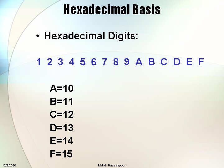
Hexadecimal Basis • Hexadecimal Digits: 1 2 3 4 5 6 7 8 9 A B C D E F A=10 B=11 C=12 D=13 E=14 F=15 12/2/2020 Mahdi Hassanpour
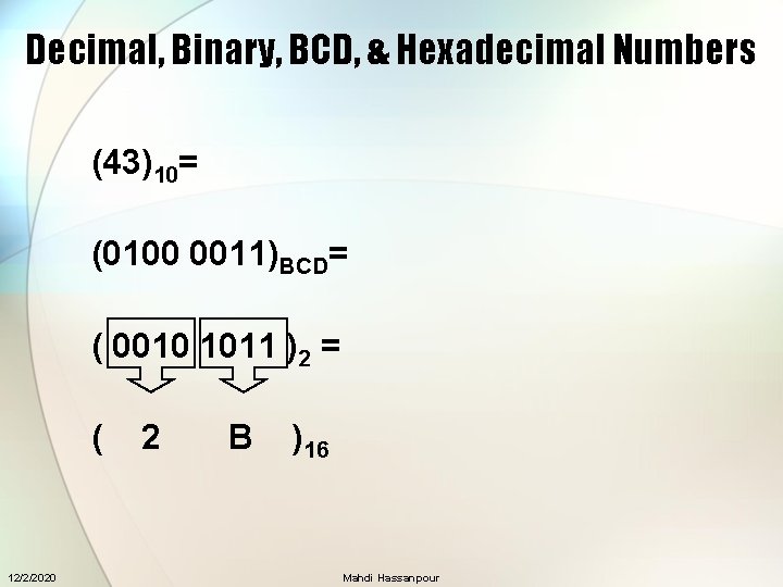
Decimal, Binary, BCD, & Hexadecimal Numbers (43)10= (0100 0011)BCD= ( 0010 1011 )2 = ( 12/2/2020 2 B )16 Mahdi Hassanpour
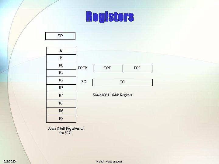
Registers SP A B R 0 DPTR DPH DPL R 1 R 2 PC PC R 3 R 4 Some 8051 16 -bit Register R 5 R 6 R 7 Some 8 -bitt Registers of the 8051 12/2/2020 Mahdi Hassanpour
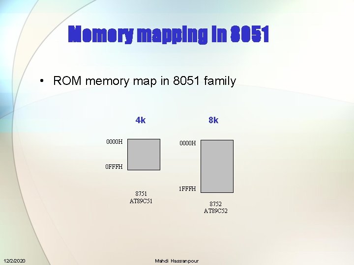
Memory mapping in 8051 • ROM memory map in 8051 family 4 k 0000 H 8 k 0000 H 0 FFFH 8751 AT 89 C 51 12/2/2020 1 FFFH 8752 AT 89 C 52 Mahdi Hassanpour
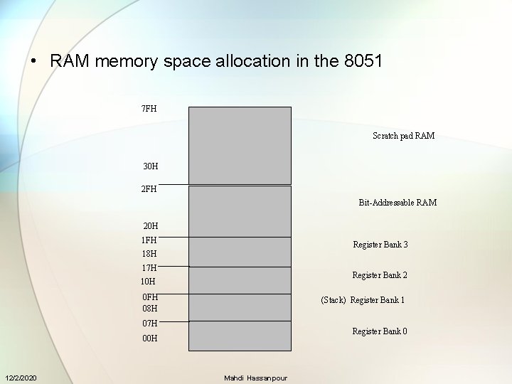
• RAM memory space allocation in the 8051 7 FH Scratch pad RAM 30 H 2 FH Bit-Addressable RAM 20 H 1 FH Register Bank 3 18 H 17 H Register Bank 2 10 H 0 FH 08 H (Stack) Register Bank 1 07 H Register Bank 0 00 H 12/2/2020 Mahdi Hassanpour
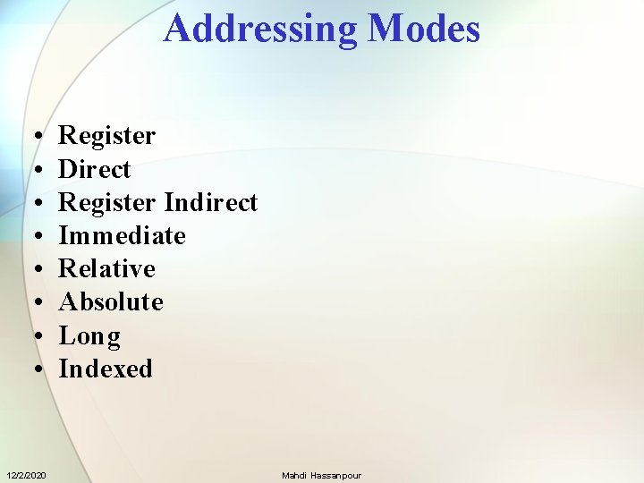
Addressing Modes • • 12/2/2020 Register Direct Register Indirect Immediate Relative Absolute Long Indexed Mahdi Hassanpour
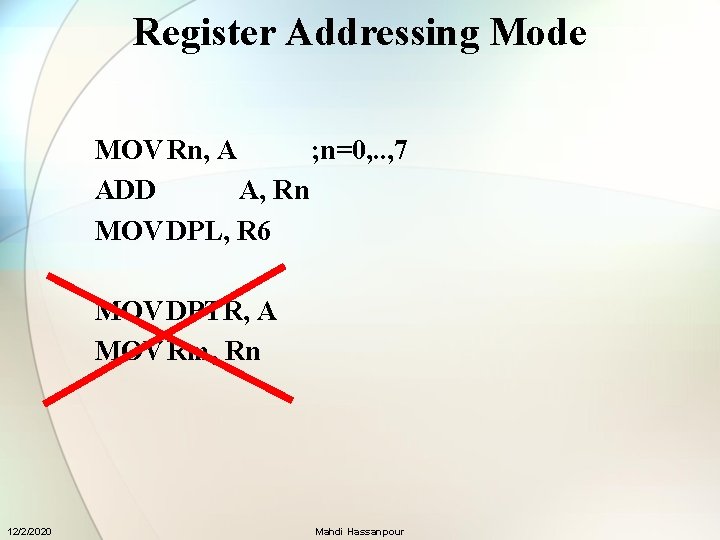
Register Addressing Mode MOV Rn, A ; n=0, . . , 7 ADD A, Rn MOV DPL, R 6 MOV DPTR, A MOV Rm, Rn 12/2/2020 Mahdi Hassanpour
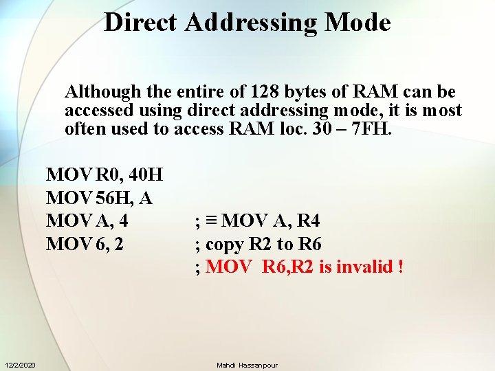
Direct Addressing Mode Although the entire of 128 bytes of RAM can be accessed using direct addressing mode, it is most often used to access RAM loc. 30 – 7 FH. MOV R 0, 40 H MOV 56 H, A MOV A, 4 MOV 6, 2 12/2/2020 ; ≡ MOV A, R 4 ; copy R 2 to R 6 ; MOV R 6, R 2 is invalid ! Mahdi Hassanpour
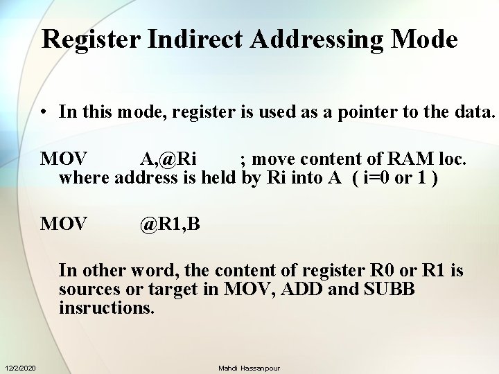
Register Indirect Addressing Mode • In this mode, register is used as a pointer to the data. MOV A, @Ri ; move content of RAM loc. where address is held by Ri into A ( i=0 or 1 ) MOV @R 1, B In other word, the content of register R 0 or R 1 is sources or target in MOV, ADD and SUBB insructions. 12/2/2020 Mahdi Hassanpour
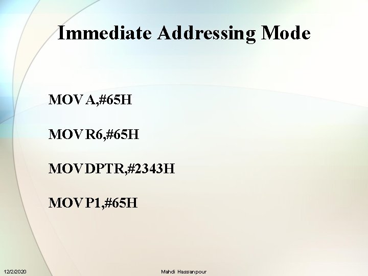
Immediate Addressing Mode MOV A, #65 H MOV R 6, #65 H MOV DPTR, #2343 H MOV P 1, #65 H 12/2/2020 Mahdi Hassanpour
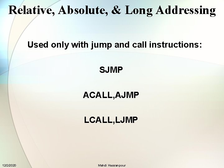
Relative, Absolute, & Long Addressing Used only with jump and call instructions: SJMP ACALL, AJMP LCALL, LJMP 12/2/2020 Mahdi Hassanpour
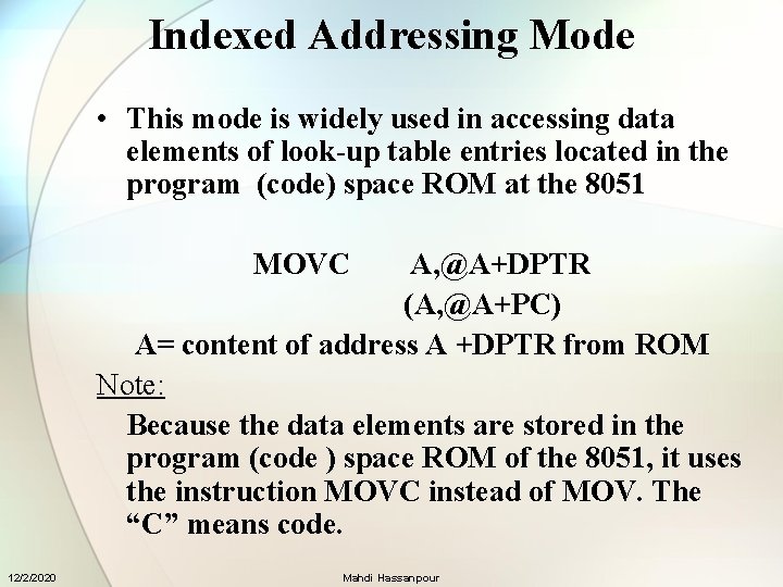
Indexed Addressing Mode • This mode is widely used in accessing data elements of look-up table entries located in the program (code) space ROM at the 8051 MOVC A, @A+DPTR (A, @A+PC) A= content of address A +DPTR from ROM Note: Because the data elements are stored in the program (code ) space ROM of the 8051, it uses the instruction MOVC instead of MOV. The “C” means code. 12/2/2020 Mahdi Hassanpour
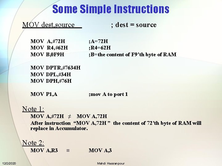
Some Simple Instructions MOV dest, source ; dest = source MOV A, #72 H MOV R 4, #62 H MOV B, 0 F 9 H ; A=72 H ; R 4=62 H ; B=the content of F 9’th byte of RAM MOV DPTR, #7634 H MOV DPL, #34 H MOV DPH, #76 H MOV P 1, A ; mov A to port 1 Note 1: MOV A, #72 H ≠ MOV A, 72 H After instruction “MOV A, 72 H ” the content of 72’th byte of RAM will replace in Accumulator. Note 2: MOV A, R 3 12/2/2020 ≡ MOV A, 3 Mahdi Hassanpour
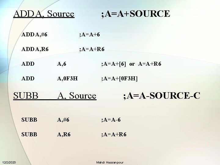
ADDA, Source ADDA, #6 ; A=A+6 ADDA, R 6 ; A=A+R 6 ADD A, 6 ; A=A+[6] or A=A+R 6 ADD A, 0 F 3 H ; A=A+[0 F 3 H] SUBB 12/2/2020 ; A=A+SOURCE A, Source ; A=A-SOURCE-C SUBB A, #6 ; A=A-6 SUBB A, R 6 ; A=A+R 6 Mahdi Hassanpour
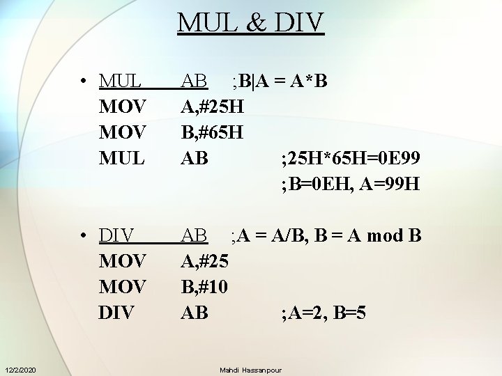
MUL & DIV 12/2/2020 • MUL MOV MUL AB ; B|A = A*B A, #25 H B, #65 H AB ; 25 H*65 H=0 E 99 ; B=0 EH, A=99 H • DIV MOV DIV AB ; A = A/B, B = A mod B A, #25 B, #10 AB ; A=2, B=5 Mahdi Hassanpour
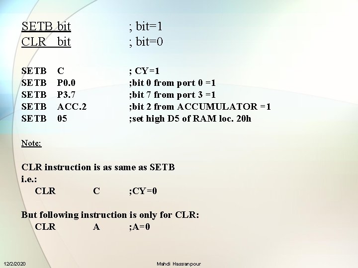
SETB bit CLR bit ; bit=1 ; bit=0 SETB SETB ; CY=1 ; bit 0 from port 0 =1 ; bit 7 from port 3 =1 ; bit 2 from ACCUMULATOR =1 ; set high D 5 of RAM loc. 20 h C P 0. 0 P 3. 7 ACC. 2 05 Note: CLR instruction is as same as SETB i. e. : CLR C ; CY=0 But following instruction is only for CLR: CLR A ; A=0 12/2/2020 Mahdi Hassanpour
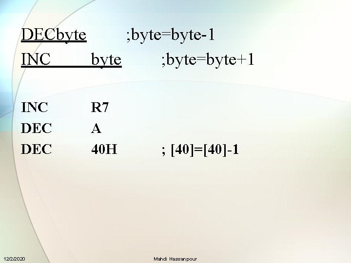
DECbyte ; byte=byte-1 INC byte ; byte=byte+1 INC DEC 12/2/2020 R 7 A 40 H ; [40]=[40]-1 Mahdi Hassanpour
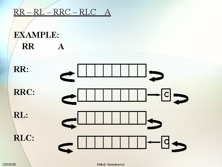
RR – RL – RRC – RLC A EXAMPLE: RR A RR: RRC: C RL: RLC: 12/2/2020 C Mahdi Hassanpour
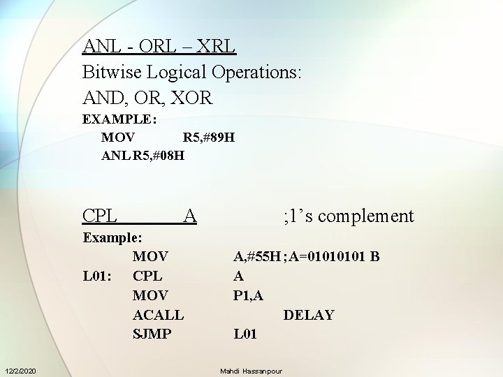
ANL - ORL – XRL Bitwise Logical Operations: AND, OR, XOR EXAMPLE: MOV R 5, #89 H ANL R 5, #08 H CPL A Example: MOV L 01: CPL MOV ACALL SJMP 12/2/2020 ; 1’s complement A, #55 H ; A=0101 B A P 1, A DELAY L 01 Mahdi Hassanpour
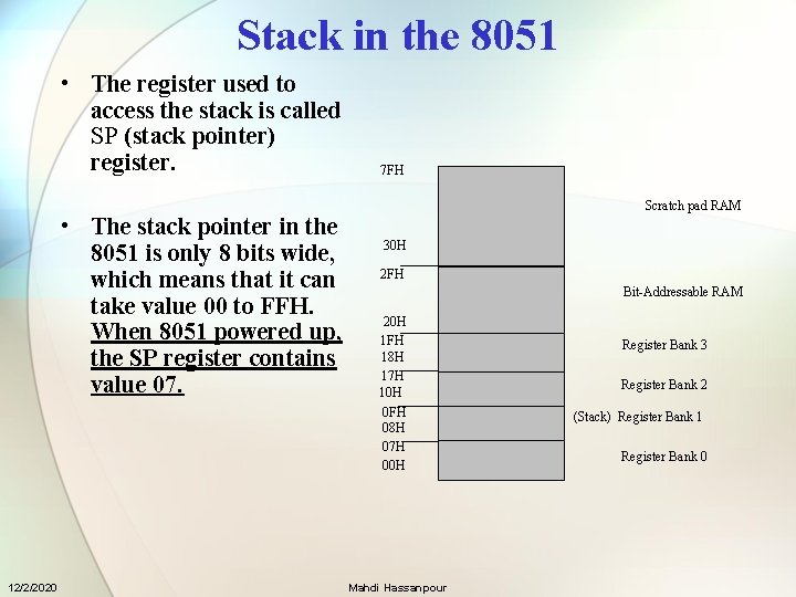
Stack in the 8051 • The register used to access the stack is called SP (stack pointer) register. 7 FH Scratch pad RAM • The stack pointer in the 8051 is only 8 bits wide, which means that it can take value 00 to FFH. When 8051 powered up, the SP register contains value 07. 12/2/2020 30 H 2 FH Bit-Addressable RAM 20 H 1 FH 18 H 17 H 10 H 0 FH 08 H 07 H 00 H Mahdi Hassanpour Register Bank 3 Register Bank 2 (Stack) Register Bank 1 Register Bank 0
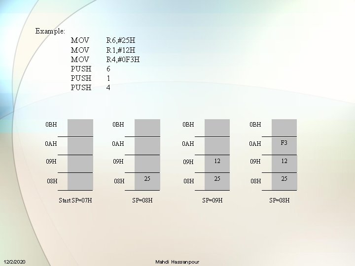
Example: MOV MOV PUSH 0 BH 0 BH 0 AH 0 AH F 3 09 H 09 H 12 08 H 08 H 25 Start SP=07 H 12/2/2020 R 6, #25 H R 1, #12 H R 4, #0 F 3 H 6 1 4 25 SP=08 H SP=09 H Mahdi Hassanpour SP=08 H
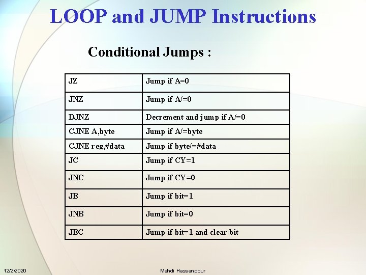
LOOP and JUMP Instructions Conditional Jumps : 12/2/2020 JZ Jump if A=0 JNZ Jump if A/=0 DJNZ Decrement and jump if A/=0 CJNE A, byte Jump if A/=byte CJNE reg, #data Jump if byte/=#data JC Jump if CY=1 JNC Jump if CY=0 JB Jump if bit=1 JNB Jump if bit=0 JBC Jump if bit=1 and clear bit Mahdi Hassanpour
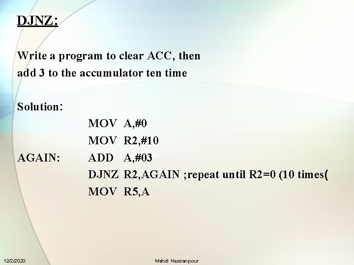
DJNZ: Write a program to clear ACC, then add 3 to the accumulator ten time Solution: AGAIN: 12/2/2020 MOV ADD DJNZ MOV A, #0 R 2, #10 A, #03 R 2, AGAIN ; repeat until R 2=0 (10 times( R 5, A Mahdi Hassanpour
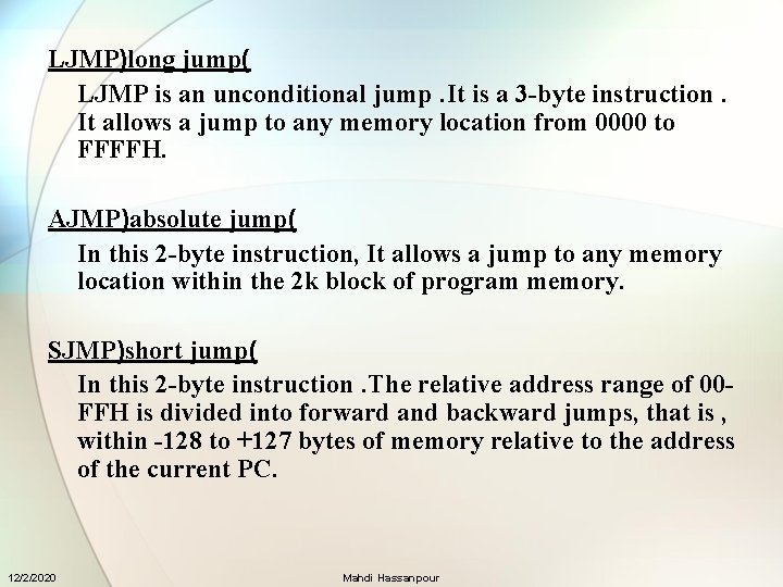
LJMP)long jump( LJMP is an unconditional jump. It is a 3 -byte instruction. It allows a jump to any memory location from 0000 to FFFFH. AJMP)absolute jump( In this 2 -byte instruction, It allows a jump to any memory location within the 2 k block of program memory. SJMP)short jump( In this 2 -byte instruction. The relative address range of 00 FFH is divided into forward and backward jumps, that is , within -128 to +127 bytes of memory relative to the address of the current PC. 12/2/2020 Mahdi Hassanpour
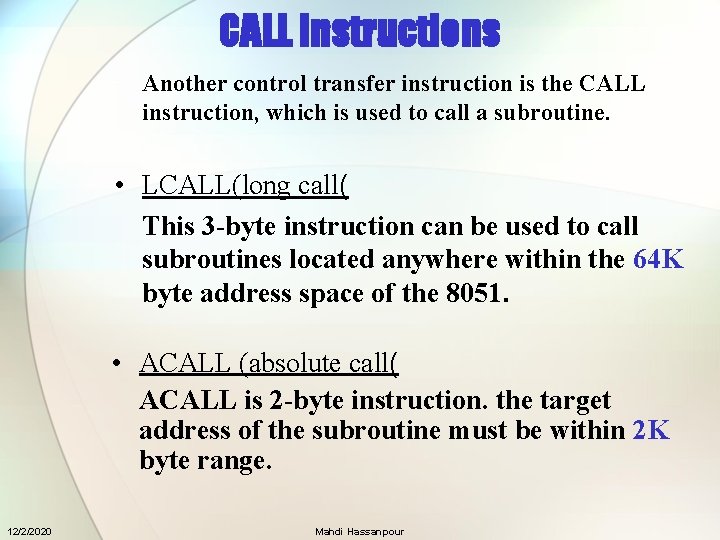
CALL Instructions Another control transfer instruction is the CALL instruction, which is used to call a subroutine. • LCALL(long call( This 3 -byte instruction can be used to call subroutines located anywhere within the 64 K byte address space of the 8051. • ACALL (absolute call( ACALL is 2 -byte instruction. the target address of the subroutine must be within 2 K byte range. 12/2/2020 Mahdi Hassanpour
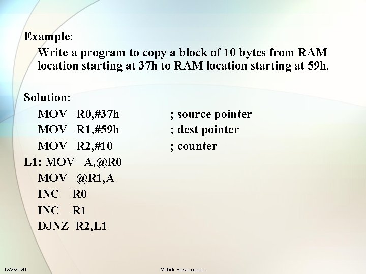
Example: Write a program to copy a block of 10 bytes from RAM location starting at 37 h to RAM location starting at 59 h. Solution: MOV R 0, #37 h MOV R 1, #59 h MOV R 2, #10 L 1: MOV A, @R 0 MOV @R 1, A INC R 0 INC R 1 DJNZ R 2, L 1 12/2/2020 ; source pointer ; dest pointer ; counter Mahdi Hassanpour
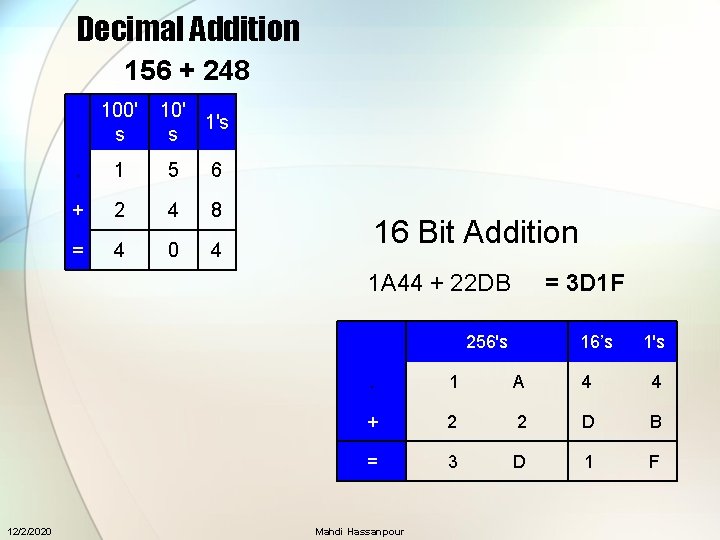
Decimal Addition 156 + 248. 100' s 10' 1's s . 1 5 6 + 2 4 8 = 4 0 4 16 Bit Addition 1 A 44 + 22 DB. 12/2/2020 = 3 D 1 F 256's 16’s 1's . 1 A 4 4 + 2 2 D B = 3 D 1 F Mahdi Hassanpour
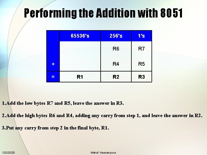
Performing the Addition with 8051. 256's 1's . R 6 R 7 + R 4 R 5 R 2 R 3 = 65536's R 1 1. Add the low bytes R 7 and R 5, leave the answer in R 3. 2. Add the high bytes R 6 and R 4, adding any carry from step 1, and leave the answer in R 2. 3. Put any carry from step 2 in the final byte, R 1. 12/2/2020 Mahdi Hassanpour
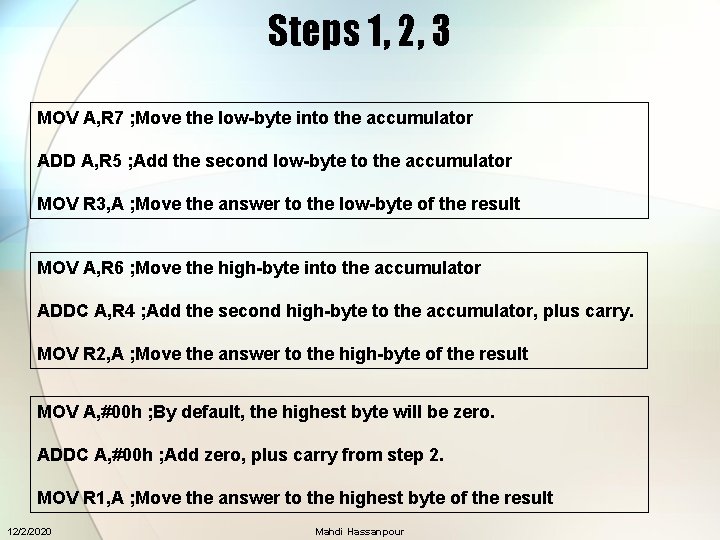
Steps 1, 2, 3 MOV A, R 7 ; Move the low-byte into the accumulator ADD A, R 5 ; Add the second low-byte to the accumulator MOV R 3, A ; Move the answer to the low-byte of the result MOV A, R 6 ; Move the high-byte into the accumulator ADDC A, R 4 ; Add the second high-byte to the accumulator, plus carry. MOV R 2, A ; Move the answer to the high-byte of the result MOV A, #00 h ; By default, the highest byte will be zero. ADDC A, #00 h ; Add zero, plus carry from step 2. MOV R 1, A ; Move the answer to the highest byte of the result 12/2/2020 Mahdi Hassanpour
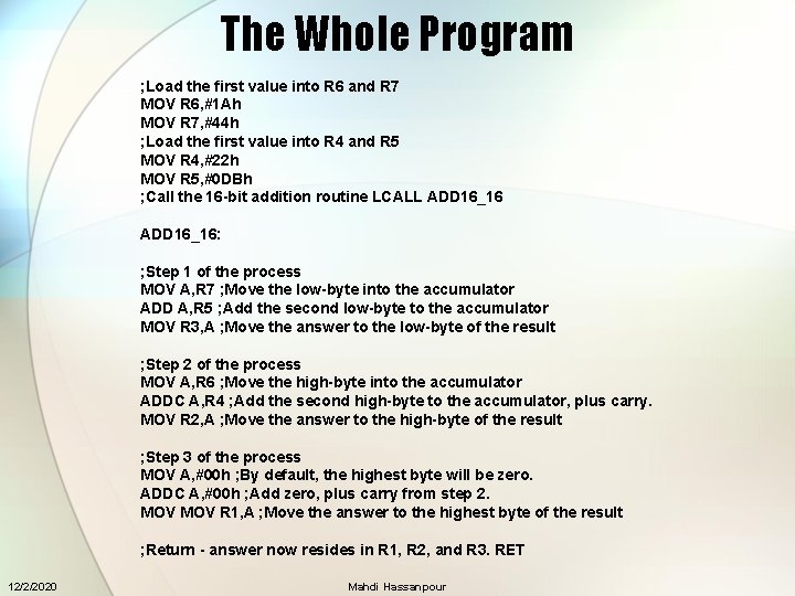
The Whole Program ; Load the first value into R 6 and R 7 MOV R 6, #1 Ah MOV R 7, #44 h ; Load the first value into R 4 and R 5 MOV R 4, #22 h MOV R 5, #0 DBh ; Call the 16 -bit addition routine LCALL ADD 16_16: ; Step 1 of the process MOV A, R 7 ; Move the low-byte into the accumulator ADD A, R 5 ; Add the second low-byte to the accumulator MOV R 3, A ; Move the answer to the low-byte of the result ; Step 2 of the process MOV A, R 6 ; Move the high-byte into the accumulator ADDC A, R 4 ; Add the second high-byte to the accumulator, plus carry. MOV R 2, A ; Move the answer to the high-byte of the result ; Step 3 of the process MOV A, #00 h ; By default, the highest byte will be zero. ADDC A, #00 h ; Add zero, plus carry from step 2. MOV R 1, A ; Move the answer to the highest byte of the result ; Return - answer now resides in R 1, R 2, and R 3. RET 12/2/2020 Mahdi Hassanpour
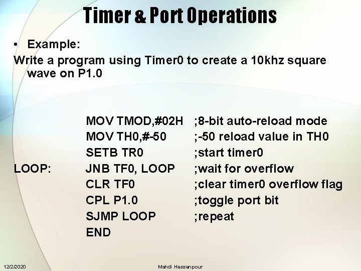
Timer & Port Operations • Example: Write a program using Timer 0 to create a 10 khz square wave on P 1. 0 LOOP: 12/2/2020 MOV TMOD, #02 H MOV TH 0, #-50 SETB TR 0 JNB TF 0, LOOP CLR TF 0 CPL P 1. 0 SJMP LOOP END ; 8 -bit auto-reload mode ; -50 reload value in TH 0 ; start timer 0 ; wait for overflow ; clear timer 0 overflow flag ; toggle port bit ; repeat Mahdi Hassanpour
Interrupts 1. Enabling and Disabling Interrupts 2. Interrupt Priority 3. Writing the ISR (Interrupt Service Routine) 12/2/2020 Mahdi Hassanpour
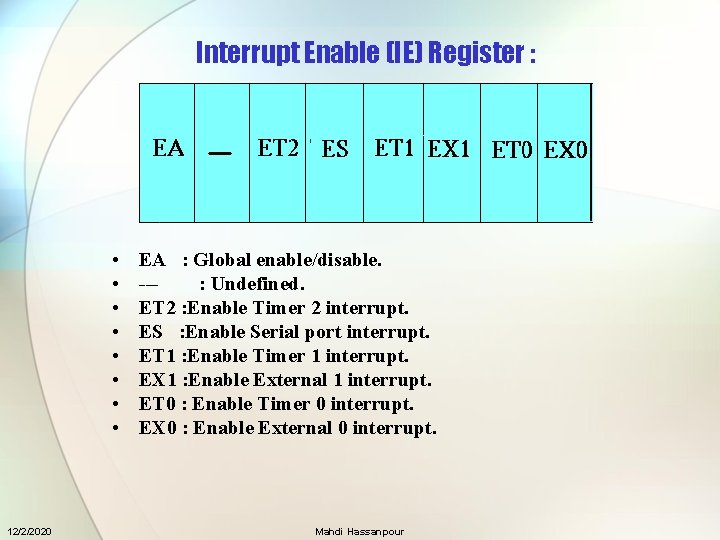
Interrupt Enable (IE) Register : • • 12/2/2020 EA : Global enable/disable. --: Undefined. ET 2 : Enable Timer 2 interrupt. ES : Enable Serial port interrupt. ET 1 : Enable Timer 1 interrupt. EX 1 : Enable External 1 interrupt. ET 0 : Enable Timer 0 interrupt. EX 0 : Enable External 0 interrupt. Mahdi Hassanpour
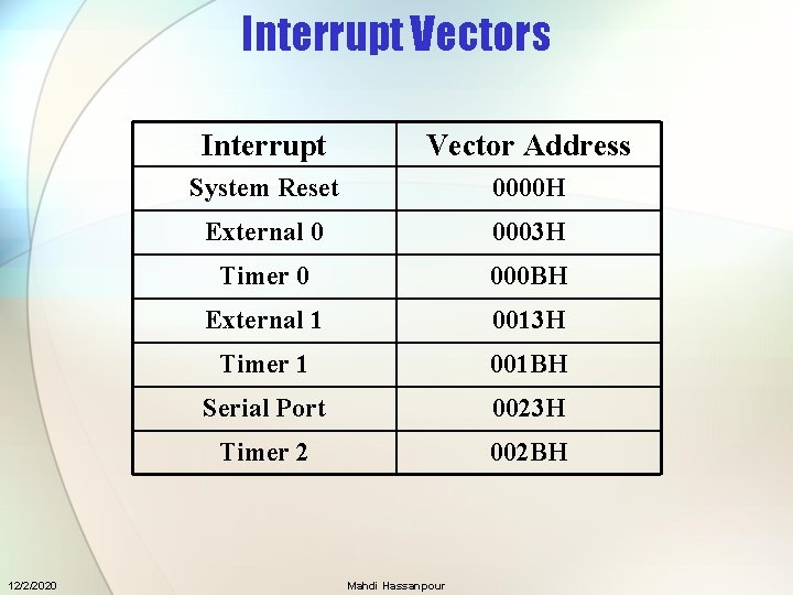
Interrupt Vectors 12/2/2020 Interrupt Vector Address System Reset 0000 H External 0 0003 H Timer 0 000 BH External 1 0013 H Timer 1 001 BH Serial Port 0023 H Timer 2 002 BH Mahdi Hassanpour
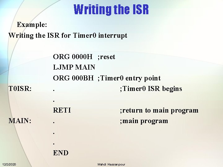
Writing the ISR Example: Writing the ISR for Timer 0 interrupt T 0 ISR: MAIN: 12/2/2020 ORG 0000 H ; reset LJMP MAIN ORG 000 BH ; Timer 0 entry point. ; Timer 0 ISR begins. RETI ; return to main program. ; main program. . END Mahdi Hassanpour
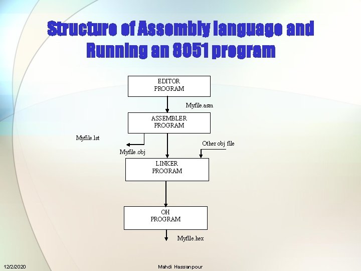
Structure of Assembly language and Running an 8051 program EDITOR PROGRAM Myfile. asm ASSEMBLER PROGRAM Myfile. lst Other obj file Myfile. obj LINKER PROGRAM OH PROGRAM Myfile. hex 12/2/2020 Mahdi Hassanpour
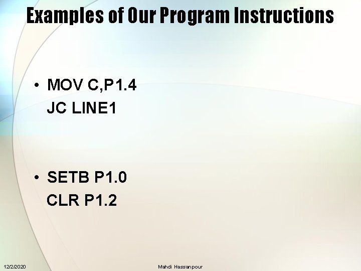
Examples of Our Program Instructions • MOV C, P 1. 4 JC LINE 1 • SETB P 1. 0 CLR P 1. 2 12/2/2020 Mahdi Hassanpour
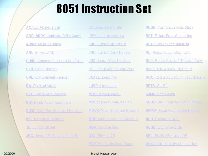
8051 Instruction Set 12/2/2020 ACALL: Absolute Call JC: Jump if Carry Set PUSH: Push Value Onto Stack ADD, ADDC: Add Acc. (With Carry) JMP: Jump to Address RET: Return From Subroutine AJMP: Absolute Jump JNB: Jump if Bit Not Set RETI: Return From Interrupt ANL: Bitwise AND JNC: Jump if Carry Not Set RL: Rotate Accumulator Left CJNE: Compare & Jump if Not Equal JNZ: Jump if Acc. Not Zero RLC: Rotate Acc. Left Through Carry CLR: Clear Register JZ: Jump if Accumulator Zero RR: Rotate Accumulator Right CPL: Complement Register LCALL: Long Call RRC: Rotate Acc. Right Through Carry DA: Decimal Adjust LJMP: Long Jump SETB: Set Bit DEC: Decrement Register MOV: Move Memory SJMP: Short Jump DIV: Divide Accumulator by B MOVC: Move Code Memory SUBB: Sub. From Acc. With Borrow DJNZ: Dec. Reg. & Jump if Not Zero MOVX: Move Extended Memory SWAP: Swap Accumulator Nibbles INC: Increment Register MUL: Multiply Accumulator by B XCH: Exchange Bytes JB: Jump if Bit Set NOP: No Operation XCHD: Exchange Digits JBC: Jump if Bit Set and Clear Bit ORL: Bitwise OR XRL: Bitwise Exclusive OR POP: Pop Value From Stack Undefined: Undefined Instruction Mahdi Hassanpour
- Slides: 40