12 TRACTIVE EFFORT AND TRACTIVE RESISTANCE NAZARIN B

12. TRACTIVE EFFORT AND TRACTIVE RESISTANCE NAZARIN B. NORDIN nazarin@icam. edu. my

What you will learn: • Tractive effort, tractive resistance, braking efficiency • Tractive resistance components: rolling/ gradient/ air resistance • Energy dissipated/ power required at constant velocity on level plane, accelerating/ braking forces applied on level plane, braking efficiency

Vehicle Dynamics CEE 320 Steve Muench

Outline 1. Resistance a. Aerodynamic b. Rolling c. Grade 2. 3. 4. 5. Tractive Effort Acceleration Braking Force Stopping Sight Distance (SSD)

Main Concepts • • • Resistance Tractive effort Vehicle acceleration Braking Stopping distance

Resistance is defined as the force impeding vehicle motion What is this force? 1. Aerodynamic resistance 2. Rolling resistance 3. Grade resistance

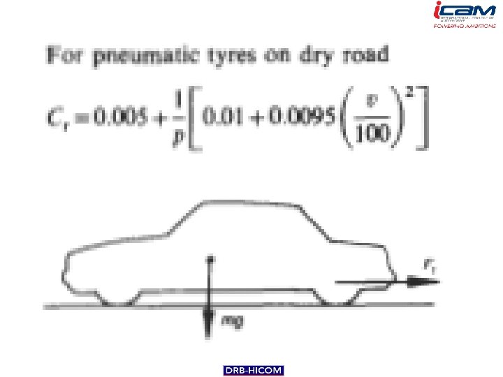
The resistance of a vehicle to motion is made up of • ‘rolling resistance’, • ‘gradient force’ and • ‘aerodynamic drag’. From the total resistance and a knowledge of the overall efficiency of the drive, the power can be calculated. Additional power is required to accelerate the vehicle. Braking torque is also dealt with.

Rolling resistance

Gradient force

Aerodynamic drag
 2.")
Aerodynamic Resistance Ra Composed of: 1. Turbulent air flow around vehicle body (85%) 2. Friction of air over vehicle body (12%) 3. Vehicle component resistance, from radiators and air vents (3%) from National Research Council Canada
 2.")
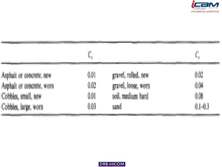
Rolling Resistance Rrl Composed primarily of 1. Resistance from tire deformation ( 90%) 2. Tire penetration and surface compression ( 4%) 3. Tire slippage and air circulation around wheel ( 6%) 4. Wide range of factors affect total rolling resistance 5. Simplifying approximation:

Grade Resistance Rg Composed of – Gravitational force acting on the vehicle θg For small angles, Rg θg W

Available Tractive Effort The minimum of: 1. Force generated by the engine, Fe 2. Maximum value that is a function of the vehicle’s weight distribution and road-tire interaction, Fmax

Tractive Effort Relationships
")
Engine-Generated Tractive Effort • Force Fe = Engine generated tractive effort reaching wheels (lb) Me = Engine torque (ft-lb) ε 0 = Gear reduction ratio ηd = Driveline efficiency r = Wheel radius (ft) • Power
 r = wheel radius (ft)")
Vehicle Speed vs. Engine Speed V = velocity (ft/s) r = wheel radius (ft) ne = crankshaft rps i = driveline slippage ε 0 = gear reduction ratio

Typical Torque-Power Curves

Maximum Tractive Effort • Front Wheel Drive Vehicle • Rear Wheel Drive Vehicle • What about 4 WD?

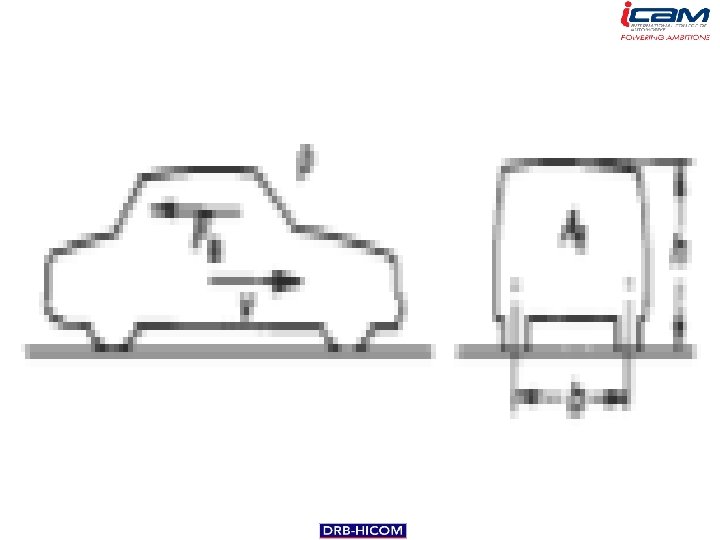
Diagram R a h ma R rlf h W f W F bf lf θg R rlr L lr W r F br θg

Vehicle Acceleration • Governing Equation • Mass Factor (accounts for inertia of vehicle’s rotating parts)

Example A 1989 Ford 5. 0 L Mustang Convertible starts on a flat grade from a dead stop as fast as possible. What’s the maximum acceleration it can achieve before spinning its wheels? μ = 0. 40 (wet, bad pavement) 1989 Ford 5. 0 L Mustang Convertible Torque 300 @ 3200 rpm Curb Weight 3640 Weight Distribution Front 57% Rear 43% Wheelbase 100. 5 in Tire Size P 225/60 R 15 Gear Reduction Ratio 3. 8 Driveline efficiency 90% Center of Gravity 20 inches high

Braking Force • Front axle • Rear axle

Braking Force • Ratio • Efficiency

Braking Distance • Theoretical – ignoring air resistance For grade = 0 • Practical • Perception
 • Worst-case conditions – Poor driver skills – Low braking")
Stopping Sight Distance (SSD) • Worst-case conditions – Poor driver skills – Low braking efficiency – Wet pavement • Perception-reaction time = 2. 5 seconds • Equation
 from ASSHTO A Policy on Geometric Design of Highways and")
Stopping Sight Distance (SSD) from ASSHTO A Policy on Geometric Design of Highways and Streets, 2001 Note: this table assumes level grade (G = 0)

SSD – Quick and Dirty 1. Acceleration due to gravity, g = 32. 2 ft/sec 2 2. There are 1. 47 ft/sec per mph 3. Assume G = 0 (flat grade) V = V 1 in mph a = deceleration, 11. 2 ft/s 2 in US customary units tp = Conservative perception / reaction time = 2. 5 seconds


Primary References • Mannering, F. L. ; Kilareski, W. P. and Washburn, S. S. (2005). Principles of Highway Engineering and Traffic Analysis, Third Edition). Chapter 2 • American Association of State Highway and Transportation Officals (AASHTO). (2001). A Policy on Geometric Design of Highways and Streets, Fourth Edition. Washington, D. C.

- Slides: 34