10 th International Ph D Workshop on Systems


 2) 3) 4) Stereo camera Stereo")
 cross viewing")


![INTRODUCTION PROBLEM RESULTS REALIZATION RESULTS (absolute distance error [%]) DISTORTED IMAGE POINTS Test object](https://slidetodoc.com/presentation_image_h2/83970f5ed1b703e7fc07977ba5196fc5/image-20.jpg "INTRODUCTION PROBLEM RESULTS REALIZATION RESULTS (absolute distance error [%]) DISTORTED IMAGE POINTS Test object")

- Slides: 21
10 th International Ph. D Workshop on Systems and Control A Young Generation Viewpoint DISTORTION IMPACT ON A STEREO DISTANCE Jernej Mrovlje Department of Systems and Control, Jožef Stefan Institute Hluboka, 25/9/09
INTRODUCTION PROBLEM REALIZATION RESULTS CONTENT ü ü ü ü stereoscopy STEDIMAT application optical aberrations (distortion) camera calibration distortion model experiment results INTRODUCTION PROBLEM REALIZATION RESULTS
INTRODUCTION PROBLEM REALIZATION RESULTS STEREOSCOPY ü ü Stereoscopy 1. a technique used for recording and presenting 3 D images 2. the viewing or appearance of objects in or as if in three dimensions Charles Wheatstone (1838): first scientist who described “stereopsis” “. . . the mind perceives an object of three dimensions my means of the two dissimilar pictures projected by it on the two ritinæ ” (C. Cheatstone) ü First stereoscopic images and stereoscope ü nowadays IMAX 3 D (Image MAXimum 3 D)
INTRODUCTION PROBLEM REALIZATION RESULTS RECORDING STEREOSCOPIC IMAGES 1) 2) 3) 4) Stereo camera Stereo attachment Camera and stereo slider* Stereo system (two single lens cameras joined together) (4) 2009 (1) (3) (2) 1947
INTRODUCTION PROBLEM REALIZATION RESULTS VEIWING STEREOSCOPIC IMAGES ü ü parallel viewing (a) cross viewing (b) (a) (b) (c) (d) anaglyph images (c) polarized images (d)
INTRODUCTION PROBLEM REALIZATION RESULTS “STEDIMAT” APPLICATION ü ü STEreo DIstance Me. Asuring Tool written in Matlab >> Matlab Compiler >> standalone application(*. exe)
INTRODUCTION PROBLEM REALIZATION RESULTS THE CALCULATION OF OBJECT’S POSITION - DISTANCE B – stereo base x 0 – horizontal image resolution φ0 – horizontal angle of view x. L – object’s position in the left image x. R – objects’ position in the right image D
INTRODUCTION PROBLEM REALIZATION RESULTS OPTICAL ABERRATIONS ü ü ü chromatic and spherical aberrations affect image quality only tangential and radial distortions affect image geometry radial distortion causes inward or outward displacement of a given image point from its ideal location ü negative radial displacement >> barrel distortion ü positive radial displacement >> pincushion distortion If the object in the image is displaced, the calculated distance is incorrect! ü inexpensive cameras with wide-angle lenses suffer barrel distortion (Canon Power. Shot A 640) ü tangential distortion is due to imperfect centering of the lens components
INTRODUCTION PROBLEM REALIZATION RESULTS DISTORTION MODEL ü distortion can be compensated mathematically: 1. 2. 3. ü ü ü applying parametric distortion model estimating distortion coefficients correcting the distortion polynomial approximation model of the radial distortion (Brown): calibration procedure was done using “Camera Calibration Toolbox for Matlab” toolbox uses Brown’s distortion model known as “Plumb Bob” RADIAL DISTORTION TANGENTIAL DISTORTION
INTRODUCTION PROBLEM REALIZATION RESULTS CALIBRATION PROCESS ü ü each camera was calibrated separately a sequence of 20 images of the calibration board was taken in different orientations in each image a set of calibration points were automatically detected using the coordinates of the distorted and undistorted calibration points, the distortion parameters kc were calculated
INTRODUCTION PROBLEM REALIZATION RESULTS CALIBRATION RESULTS left camera ü ü centre of the image: displacement < 10 px corners of the image: displacement > 100 px right camera
INTRODUCTION PROBLEM REALIZATION RESULTS CORRECTING THE DISTORTION #1 ü ü distortion model was used to build “distortion-correction function” (DCF) as a part of Stedimat for each distance DCF has to be applied twice: 1. 2. using image point of the object’s location in the left image (x. L) using image point of the object’s location in the right image (x. D) “EXPERIMENT”/equipment: ü stereoscopic system with 2 digital cameras Canon Power. Shot A 640 ü Stereo. Data Maker was used to synchronize cameras
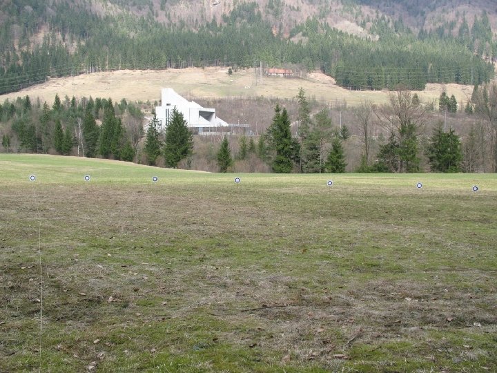
INTRODUCTION PROBLEM REALIZATION RESULTS CORRECTING THE DISTORTION #2 “EXPERIMENT”: ü 7 test objects positioned at the distance D (30, 40, 50 and 60 m) >>> four sets of stereoscopic images ü image resolution: 3648 x 2736, focal distance: 35 mm, stereo base: 0. 56 m, reference object : test object no. 4 ü distance to each test object was calculated twice: undistorted/distorted image
INTRODUCTION PROBLEM REALIZATION RESULTS CORRECTING THE DISTORTION #2 EXPERIMENT: ü 7 test objects positioned at the distance D (30, 40, 50 and 60 m) >>> four sets of stereoscopic images ü image resolution: 3648 x 2736, focal distance: 35 mm, stereo base: 0. 56 m, reference object : test object no. 4 ü distance to each test object was calculated twice: 1–distorted image points, 2 -distortion-free image points
INTRODUCTION PROBLEM RESULTS #1 REALIZATION RESULTS
INTRODUCTION PROBLEM RESULTS #2 REALIZATION RESULTS
INTRODUCTION PROBLEM RESULTS #3 REALIZATION RESULTS
INTRODUCTION PROBLEM RESULTS #4 REALIZATION RESULTS
INTRODUCTION PROBLEM RESULTS REALIZATION RESULTS (absolute distance error [%]) DISTORTED IMAGE POINTS Test object 1 2 3 4 5 6 7 Dref=30 m 4, 3 2, 9 3, 1 6, 4 11, 7 Dref=40 m Dref=50 m 3, 9 7, 0 3, 8 4, 8 0 (reference point) 6, 4 8, 1 8, 7 14, 2 16, 2 28, 9 Dref=60 m 5, 6 6, 4 17, 6 31, 5 DISTORTION-FREE IMAGE POINTS Test object 1 2 3 4 5 6 7 Dref=30 m 1, 5 3, 3 2, 2 0, 5 1, 1 5, 3 Dref=40 m Dref=50 m 0, 5 1, 9 1, 8 4, 4 2, 5 3, 0 0 (reference point) 1, 9 2, 8 1, 7 1, 1 8, 0 2, 3 Dref=60 m 0, 5 1, 6 3, 1 0, 5 1, 2 3, 4