10 1 GPIO PIN 10 2 GPIO Device


 5")
 7")
 ® Six determine whether")
 ® 앞 슬라이드에서 보았던")
 11")
 12")
 13")


")
")
")
")
")
 static")
 open() key_init() Key_read() Interruptible_sleep_on()")
 26")
 27")
 28")

")
")
")
")
![10. 2 GPIO 제어용 Device Driver ± application 만들기 static char gpio_test. Dev[] =](https://slidetodoc.com/presentation_image_h/fad8007ff4e48723f1a830f5728d291e/image-34.jpg "10. 2 GPIO 제어용 Device Driver ± application 만들기 static char gpio_test. Dev[] =")
{ int dev; char buf; if((dev =")


 1")
 #define")
 mem_addr_fnd")
 unsigned")
 main(int")

- Slides: 51
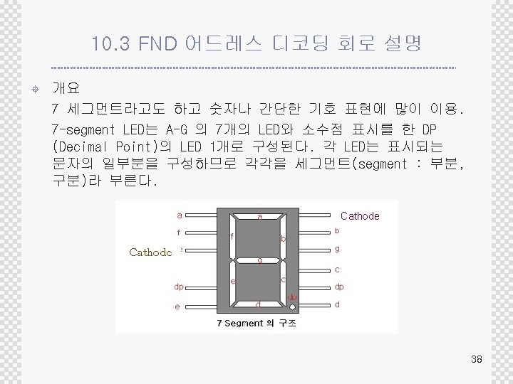
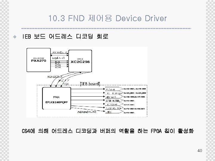
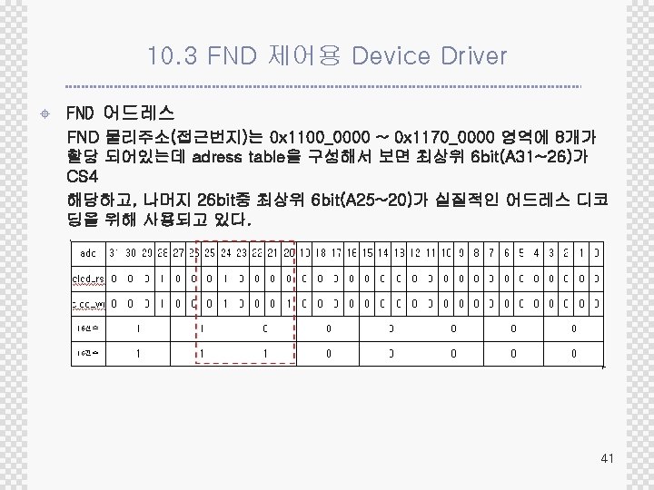
목차 10. 1 GPIO PIN 설명 10. 2 GPIO 제어용 Device Driver 10. 3 FND 어드레스 디코딩 회로 설명 11. 4 FND 제어용 Device Driver 2
10. 1. 1 GPIO ± GPIO와 Interrupt를 이용한 char device driver를 제작해보자. ® XHYPER 270 -TKU board에 GPIO test를 위한 2개의 key와 led가 있다. ® key를 눌렸을 때 interrupt발생하게 하여 interrupt service routine이 실행되면서 LED를 점등하게 한 다. ® GPIO 35, 36, 37, 41은 interrupt를 위해 입력I/O로 셋팅하고, GPIO 3, 4는 led 점등을 위한 출력 I/O 로 셋팅한다. 3
10. 1. 1 GPIO ± GPIO – LED GPIO Pin Alignment GPIO_LED 0와 GPIO_ LED 1이 GPIO 3, 4에 물려 있음. GPIO는 General-purpost I/O ports의 의미로 일반적인 목적으 로 입출력 하는 포트를 말함. PXA 270는 118개의 GPIO 포트 가 chip의 pin으로 나와 있다. 4
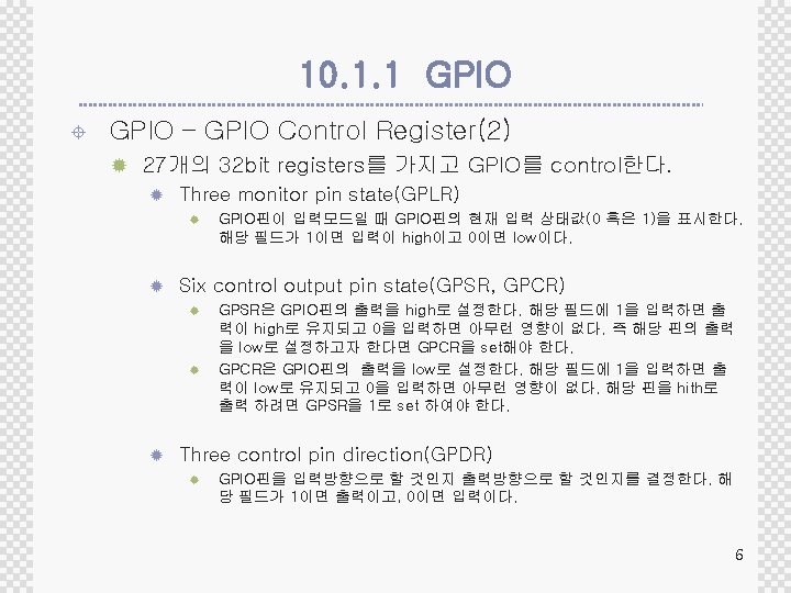
10. 1. 1 GPIO ± GPIO Control Register(1) 5
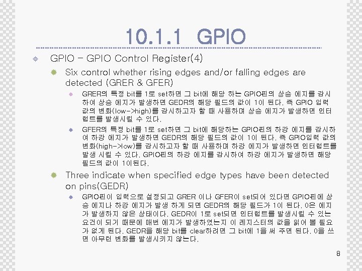
10. 1. 1 GPIO ± GPIO – GPIO Control Register(3) 7
10. 1. 1 GPIO ± GPIO – GPIO Control Register(5) ® Six determine whether a pin is used as a normal GPIO or whether it is to be taken over by one of three possible alternate functions (GAFR_L, GAFR_U) ® GPIO핀을 특정 기능을 위한 핀으로 쓸 것인지 GPIO핀으로 쓸 것인지를 결정한다. 1이면 특정 기능으로 설정하고, 0이면 GPIO로 설정한다. 9
10. 1. 1 GPIO ± GPIO – GPIO Control Register(6) ® 앞 슬라이드에서 보았던 우리가 다룰 Register Definition 10
10. 1. 1 GPIO ± GPIO – GPIO Control Register(7) 11
10. 1. 1 GPIO ± GPIO – GPIO Control Register(8) 12
10. 1. 2 Key Button ± Key Hardware – scheme(1) 13
GPIO LED Device Driver www. huins. com
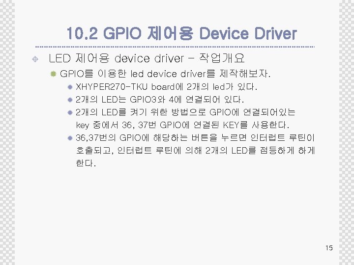
10. 2 GPIO 제어용 Device Driver ± LED 제어용 device driver ® 우리가 다룰 Register Definition(1) ® GPIO 3, 4번의 입/출력 방향을 결정한다. 16
10. 2 GPIO 제어용 Device Driver ± LED 제어용 device driver ® 우리가 다룰 Register Definition(2) 17
10. 2 GPIO 제어용 Device Driver ± LED 제어용 device driver – driver coding(1) #include <linux/module. h> //모듈에 관한 정의 #include <linux/init. h> //init_module() 과 cleanup_module() #include <asm/uaccess. h> //copy_to_user() #include <asm/io. h> #include <asm/arch/pxa-regs. h> //GPIO controller에 관한 정의 18
10. 2 GPIO 제어용 Device Driver ± LED 제어용 device driver – driver coding(2) #define …. #define GPIO_LED 1 GPIO_LED 2 GPIO_bit(3) //gpio 3번 핀 GPIO_bit(4) //gpio 4번 핀 GPIO_TEST_MAJOR GPIO_TEST_NAME 241 // 메이저 번호 "GPIO_TEST“ // 디바이스 이름 GPIO_LED 1_ON_OFF 0 x 2000 //IOCTL 매직번호 GPIO_LED 2_ON_OFF 0 x 2100 //IOCTL 매직번호 19
10. 2 GPIO 제어용 Device Driver ± LED 제어용 device driver – driver coding(3) static int gpio_test_open(struct inode *inode, struct file *filp) { printk("GPIO TEST OPENn"); GPSR 1 = (GPIO_bit(3) | GPIO_bit(4)); // LED Inital Clear if(led_usage != 0) return -EBUSY; led_usage = 1; return 0; } …. . static int gpio_test_release(struct inode *inode, struct file *filp){ led_usage = 0; return 0; } 20
10. 2 GPIO 제어용 Device Driver ± LED 제어용 device driver – driver coding(5) static struct file_operations gpio_test_fops = {. open = gpio_test_open, . read = gpio_test_read, . write = gpio_test_write, . ioctl = gpio_test_ioctl, . release = gpio_test_release, }; 21
10. 2 GPIO 제어용 Device Driver ± LED 제어용 device driver – driver coding(6) static int gpio_test_init(void){ …… // GPLED 1, GPLED 2 Setting GAFR 1_L &= ~((1<<9)|(1<<8) | (1<<7)|(1<<6)); GPDR 1 |= (GPIO_LED 1 | GPIO_LED 2); GPSR 1 = (GPIO_LED 1 | GPIO_LED 2); //켜기 GPCR 1 = (GPIO_LED 1 | GPIO_LED 2); //끄기 //GPIO 3, 4 //Output Pin 22
10. 2 GPIO 제어용 Device Driver LED 제어용 device driver – application coding(2) static void gpio_test_exit(void){ GPSR 1 = (GPIO_bit(35) | GPIO_bit(41)); // LED Clear ± GPIO 셋팅을 통해 LED쪽 드라이버 부분은 완성되었다. 이제 key입력을 위한 드라이버 코딩을 살펴보자. 23
10. 2 GPIO 제어용 Device Driver start Application start module_init() open() key_init() Key_read() Interruptible_sleep_on() key_read() 함수 call read() blocking read() waiting key interrupt key_handler() wakeup_interruptible() read() waking 25
10. 2 GPIO 제어용 Device Driver ± 우리가 다룰 Register Definition(1) 26
10. 2 GPIO 제어용 Device Driver ± 우리가 다룰 Register Definition(2) 27
10. 2 GPIO 제어용 Device Driver ± 우리가 다룰 Register Definition(2) 28
10. 2 GPIO 제어용 Device Driver ± ± ± GFER을 통하여 GPIO falling edge일때 검출 설정 GAFR을 통하여 alternate function 설정 GPDR을 통하여 GPIO 입출력 방향 설정 request_irq() 함수로 interrupt 등록 set_irq_type() 함수로 interrupt 검출 설정 29
10. 2 GPIO 제어용 Device Driver ± LED 제어용 device driver – application coding(1) …. . #define IRQ_KEY 1 IRQ_GPIO(36) #define IRQ_KEY 2 IRQ_GPIO(37) …. #define GPIO_KEY_READ 0 x 1000 //IOCTL 매직번호 …. . char key_buf; …. . DECLARE_WAIT_QUEUE_HEAD(key_queue); 30
10. 2 GPIO 제어용 Device Driver ± LED 제어용 device driver – application coding(2) static int gpio_test_init(void){ int result, ret; …. . if ((ret = request_irq(IRQ_KEY 1, &key_interrupt SA_INTERRUPT, "GPIO 36_KEY 1", NULL))), Interrupt를 등록하는 함수. { printk("failed to register IRQ KEY 1n"); Int request_irq(unsingned int irq_number, void (*handler)(int, struct pt_regs *), return ret; unsigned long irqflags, const char *devicename, void *dev_id); Key_handler는 interrupt가 걸렸을때 처리하는 함수, 등록이 성공하면 } # cat /proc/interrupts명령으로 interrupt가 등록되어 있는 것을 확인. . . set_irq_type(IRQ_KEY 1, IRQT_FALLING); // 2. 6 Kernel …. GFER 1 |= (GPIO_bit(36) | GPIO_bit(37)); // falling edge일때 인터 럽트 검출하도록 설정 31
10. 2 GPIO 제어용 Device Driver ± LED 제어용 device driver – application coding(3) static irqreturn_t key_interrupt(int irq, void *dev_id, struct pt_regs *regs){ DUMMY_DELAY; if((GEDR 1 & GPIO_bit(36))) { key_buf = 1; } if((GEDR 1 & GPIO_bit(37))) { key_buf = 2; } wake_up_interruptible(&key_queue); return IRQ_HANDLED; } 32
10. 2 GPIO 제어용 Device Driver ± LED 제어용 device driver – application coding(4) int gpio_test_ioctl(struct inode *inode, struct file *filp, unsigned int cmd, unsigned long arg){ 사용자 프로그램으로 값을 넘긴다. int data = 0; int ret = 0; /*You can add any ioctl command*/ switch (cmd) { case GPIO_KEY_READ: copy_to_user((void *)arg, &key_buf, sizeof(key_buf)); 사용자 프로그램에서 값을 받아 온다. key_buf = 0; return 0; case GPIO_LED 1_ON_OFF: copy_from_user(&data, (void *)arg, sizeof(data)); if( data == 1) GPSR 1 = GPIO_LED 1; //GPIO 35 SET LED OFF else GPCR 1 = GPIO_LED 1; //GPIO 35 CLEAR LED ON return 0; case GPIO_LED 2_ON_OFF: copy_from_user(&data, (void *)arg, sizeof(data)); if( data == 1) GPSR 1 = GPIO_LED 2; //GPIO 41 SET LED OFF else GPCR 1 = GPIO_LED 2; //GPIO 41 CLEAR LED ON return 0; default: return -EINVAL; } 33
10. 2 GPIO 제어용 Device Driver ± application 만들기 static char gpio_test. Dev[] = "/dev/GPIO_TEST"; #define GPIO_KEY_READ 0 x 1000 #define GPIO_LED 1_ON_OFF 0 x 2000 IOCTL 매직 번호 #define GPIO_LED 2_ON_OFF 0 x 2100 int ON = 0; int OFF = 1; 34
10. 2 GPIO 제어용 Device Driver int main(){ int dev; char buf; if((dev = open(gpio_test. Dev, O_RDWR )) < 0){ faile /dev/GPIO_TESTn"); exit(-1); } while(1){ read(dev , &buf, sizeof(buf)); // Key READ printf("KEY %d PUSH n", buf); switch(buf){ case 1: { ioctl(dev, GPIO_LED 1_ON_OFF, &ON); perror("open 35
10. 2 GPIO 제어용 Device Driver ± Makefile CC : = /opt/iwmmxt-1. 0. 0/bin/arm-linux-gcc. K DIR: = /PXA 270/kernel/linux-2. 6. 11 -h 270 -tku_v 1. 1 TEST_TARGET = test TEST_OBJS = $(TEST_TARGET). o TEST_SRCS = test. c obj-m : = gpio_test. o build: $(TEST_TARGET) make -C $(KDIR) SUBDIRS=`pwd` modules $(TEST_TARGET): $(TEST_OBJS) $(CC) -o $@ $(TEST_OBJS) clean: rm -rf *. 0 *. ko *. mod. c rm -f $(TEST_TARGET) 36
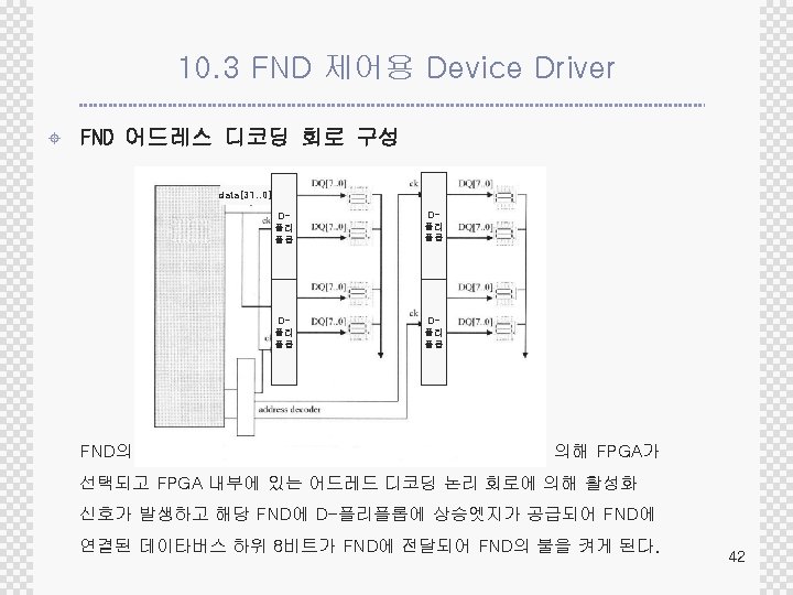
10. 3 FND 제어용 Device Driver ± FND 디바이스 물리 주소 영역 n. CS 4번 영역인 0 x 1000_0000 ~ 0 x 13 FF_FFFF 사이에 FND 존재 39
10. 3 FND 제어용 Device Driver ± FND 제어 방법(해당 비트에 데이터를 보냄) 1 : FND_CS = (0 x 01 << 0) 7 : FND_CS = (0 x 01 << 6) FND 6 : FND_CS = (0 x 01 << 5) 2 : FND_CS = (0 x 01 << 1) 3 : FND_CS = (0 x 01 << 2) 5 : FND_CS = (0 x 01 << 4) 8 : FND_CS = (0 x 01 << 7) 4 : FND_CS = (0 x 01 << 3) 43
10. 3 FND 제어용 Device Driver ± FND 드라이버 소스 설명 (fnd. c) #define #define FPGA_FND_CS 0 FPGA_FND_CS 1 FPGA_FND_CS 2 FPGA_FND_CS 3 FPGA_FND_CS 4 FPGA_FND_CS 5 FPGA_FND_CS 6 FPGA_FND_CS 7 (0 x 11000000) //FND 물리주소 (0 x 11100000) (0 x 11200000) (0 x 11300000) (0 x 11400000) (0 x 11500000) (0 x 11600000) (0 x 11700000) 46
10. 3 FND 제어용 Device Driver ± FND 드라이버 소스 설명 (fnd. c) mem_addr_fnd 0 = FPGA_FND_CS 0; …… mem_len = 0 x 1000; …. . static int fnd_init(void){ mem_fnd_cs 0 = ioremap_nocache ( mem_addr_fnd 0, mem_len); //가상주소 얻기 if( !mem_fnd_cs 0) { printk("Error mapping fnd 0 memery"); return -EBUSY; } ……. static void fnd_exit(void){ fnd_clear(); unregister_chrdev(FND_MAJOR, FND_NAME); iounmap(mem_fnd_cs 0); 47
10. 3 FND 제어용 Device Driver ± FND 응용프로그램 소스 설명 (fnd_test. c) unsigned char asc_to_fnd(int n){ unsigned char c; switch (n) { /* 여러가지 문자를 추가할수 있다 */ case 0: c = 0 x 3 f; break; case 1: c = 0 x 06; break; case 2: c = 0 x 5 b; break; case 3: c = 0 x 4 f; break; case 4: c = 0 x 66; break; case 5: c = 0 x 6 d; break; case 6: c = 0 x 7 d; break; case 7: c = 0 x 07; break; …. . } return c; } 48
10. 3 FND 제어용 Device Driver ± FND 응용프로그램 소스 설명 (fnd_test. c) main(int ac, char *av[]){ int n, count, dev; unsigned char buf[MAXFND+1]; dev = open( fnd_dev, O_RDWR); if (dev < 0) {fprintf(stderr, "cannot open FND (%d)", dev); exit(2); } memset(buf, 0, sizeof(buf)); for (n = 0 ; n <= 9; n++) { for( count = 0 ; count < MAXFND; count++){ buf[count]= asc_to_fnd(n); } write(dev, buf, MAXFND); usleep(500000); } } 49
10. 3 FND 제어용 Device Driver ± Makefile 설명 CC : = /opt/iwmmxt-1. 0. 0/bin/arm-linux-gcc KDIR : = /PXA 270/kernel/linux-2. 6. 11 -h 270 -tku_v 1. 1 TEST_TARGET = fnd_test TEST_OBJS = fnd_test. o TEST_SRCS = fnd_test. c obj-m : = fnd. o build: $(TEST_TARGET) make -C $(KDIR) SUBDIRS=`pwd` modules $(TEST_TARGET) : $(TEST_OBJS) $(CC) -o $@ $(TEST_OBJS) clean: rm -rf *. o *. ko *. mod. c rm -f $(TEST_TARGET) 50