1 Terminology A Gross Pressure Intensity q Total
 Gross Pressure Intensity (q) Total pressure at the base of footing")
 Net Safe Bearing Capacity (qns) Net Ultimate Bearing Capacity divided by FOS. qns")


 2. 1 Shallow/Open Foundations in")


 Plate Load Test (Ref. : IS: 1888 -1982) Apparatus Loading Plate - Circular")


 Based on Settlement of Plate Settlement")
 Bearing Capacity from Strength Parameters (I) Terzaghi’s Bearing Capacity Theory Zone-I : Soil")
 Modes of Failure (i) General Shear Failure • There are well defined slip")
 Punching Shear Failure • Footing sinks into soil like a punch. • The")
 Local Shear Failure • Intermediate failure mode, with characteristics of both general and")
 Provisions of IS: 6403 -1981 (i) For C – Ø Soils Net Ultimate")


 Effect of Eccentricity of Load (With respect to Centroid of Foundation)")
 For Cohesionless Soils (C = 0) (a) To decide Mode of Failure (b)")
 Based on SPT “N” Value Determine “N” values at a number of selected")
 For Cohesive Soils (Ø = 0) (a) For Homogeneous Layer Net Ultimate Bearing")

 of 6 to")

 On Coarse Grained / Non-cohesive Soils Settlement takes")
 Based on Plate Load Test Perform Plate Load Test at the proposed foundation")
 On Fine Grained Soils (Clause 6. 4. 2 of Sub-structure Code) Settlement below")
![Poed = [Ht/(1+e 0)] * Cc * log 10 [(P 0+ΔP)/P 0] Where:](https://slidetodoc.com/presentation_image_h/07938586c471713636598a291915ea66/image-36.jpg "Poed = [Ht/(1+e 0)] * Cc * log 10 [(P 0+ΔP)/P 0] Where:")
 Correction for Depth and Rigidity of Foundation Effect of Depth of Foundation The")
 Permissible Settlement Values (Table-1, IS: 1904 -1986)")


- Slides: 40
1. Terminology (A) Gross Pressure Intensity (q) Total pressure at the base of footing due to weight of superstructure, self weight of footing and weight of earth fill etc. (B) Net Pressure Intensity (qn) Excess pressure, or difference in intensities of gross pressure after the construction of structure. qn = q – σ = q – γ*D D = Depth of footing (C) Ultimate Bearing Capacity (qf) Minimum gross pressure intensity at the base of foundation at which soil fails in shear. (D) Net Ultimate Bearing Capacity (qnf) Minimum net pressure intensity at the base of foundation at which soil fails in shear. qnf = qf - σ = qf – γ*D D = Depth of footing
(E) Net Safe Bearing Capacity (qns) Net Ultimate Bearing Capacity divided by FOS. qns = qnf/F Factor of Safety (F) = 2. 5 (F) Safe Bearing Capacity (qs) Maximum pressure which the soil can carry safely without Shear failure. qs = qns + γ*D = qnf/F + γ*D (G) Safe Bearing Pressure for Specified Settlement The maximum allowable pressure to which the foundation may be subjected without producing excessive Settlement or excessive Differential Settlement of the structure. (H) Allowable Bearing Capacity Lesser of the (E) and (G).
Safe Bearing Capacity is the capacity of soil or rock, which is considered for designing the foundations. The value of safe bearing capacity for a few types of soils is indicated below : Type of Soil Safe Bearing Capacity in Tonnes/m 2 Soft clay 10 Fine Sand Silt 15 Hard Stiff Clay 25 – 40 Coarse Sand comacted 45 Soft Rock 45 Sand Stone 165 Granite 330
Methods for improving Safe Bearing Capacity In case the safe bearing capacity of available soil is poor, the same can be improved by the following methods : (i) By increasing the depth of foundation. (ii)By blending granular materials such as sand, gravel or crushed stone. (iii)By providing sand piles and (iv)By improving the drainage or lowering the water level.
2. Type of Foundations (As per IS: 1904 -2000) 2. 1 Shallow/Open Foundations in which load transfer is primarily through shear resistance of bearing strata. Normally laid up to a depth of 3 m. Spread or Pad Footing Strip Footing Raft or Mat Footing Ring and Shell Footing
2. 2 Deep Foundations Used to transmit the loads to deeper load bearing strata, when adequate bearing strata does not exist at shallow depths. Transfer of load is through end bearing resistance or skin friction or combination of both. Pile Foundation Well Foundation Caisson Foundations
3. Provisions of Sub-structure Code and elaboration related issues
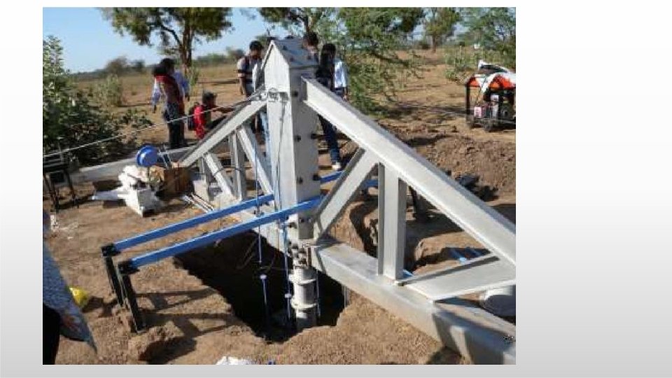
(A) Plate Load Test (Ref. : IS: 1888 -1982) Apparatus Loading Plate - Circular or Square plates of mild steel not less than 25 mm in thickness, Sizes from 300 mm to 750 mm. Loading set-up, of any of the following types : o Gravity loading o Reaction loading o Loading truss Hydraulic Jack of required capacity with properly calibrated measuring device for load measurement. Settlement recording device (dial gauges with 25 mm travel & capable of measuring settlement to an accuracy of 0. 01 mm). Datum beam or rod of sufficient strength.
Gravity Loading Platform
Reaction Loading Platform
Loading Truss
Procedure Normally the test shall be conducted at depth of proposed foundation level. Width of test pit - 5 times the width of test plate. Size of test plate - At least 4 times the maximum size of soil particles. For clayey and silty soils/loose to medium dense sandy soils with N < 15, use 450 mm square plate. For dense sandy/gravely soils (15 < N < 30) use plates of sizes 300 mm to 750 mm. Loading platform support at least 2. 5 m from test area, at more than 1 m above the bottom of pit. No support should be within 3. 5 times size of test plate from its centre. Apply seating pressure of 70 g/cm 2 and remove. Then apply load in increments of 1 kg/cm 2 or 1/5 th of estimated ultimate bearing capacity (whichever is less). Observe settlement for each increment of load after an interval of 1, 2. 25, 4, 6. 25, 9, 16 and 25 minutes and thereafter at hourly intervals, to the nearest 0. 02 mm. The test shall be continued till settlement of 25 mm in normal cases or 50 mm in special cases (such as dense gravel, gravel and sand mixture) is obtained or till failure occurs.
Ultimate Bearing Capacity from Load Settlement Curve
If Yield point not well defined – Curve A and C
Settlement of Footing (for Medium and Dense Sand) Based on Settlement of Plate Settlement of footing (Sf) Sf = Sp [{B (Bp+0. 3)}2 / {Bp (B +0. 3)}2] Where – B = Size of footing in mm. Bp = Size of test plate in mm. Sp = Settlement of test plate in mm.
(B) Bearing Capacity from Strength Parameters (I) Terzaghi’s Bearing Capacity Theory Zone-I : Soil Wedge under Footing Zone-II : Plastic (Active) Zone-III : Passive Zone
(II) Modes of Failure (i) General Shear Failure • There are well defined slip surface/failure planes from edge of footing to adjacent ground. • Footing suddenly sinks into the ground, with heave of adjacent ground. • The Load - Settlement curve shows pronounced peak & failure occurs at very small strain. • Happens mostly in dense sand stiff clays.
(ii) Punching Shear Failure • Footing sinks into soil like a punch. • The failure surface do not extend up to the ground surface. No heave is observed. • There is vertical shear around the footing perimeter and with soil on the sides of footing remaining practically uninvolved. • Large vertical strains are involved.
(iii) Local Shear Failure • Intermediate failure mode, with characteristics of both general and punching shear failure modes. • The slip lines immediately below the footing extend only a short distance into the soil mass. Then they extend gradually extend outwards, leading to ultimate failure. • The failure occurs at large vertical strain. The load settlement curve does not indicate the bearing capacity clearly. • Happens mostly in loose sand soft clay.
(III) Provisions of IS: 6403 -1981 (i) For C – Ø Soils Net Ultimate Bearing Capacity For General Shear Failure: Qd = C Nc sc dc ic + q (Nq-1) sq dq iq + 0. 50 B γ Nγ sγ dγ iγ W’ For Local Shear Failure: Q’d = 0. 67 C N’c sc dc ic + q (N’q-1) sq dq iq + 0. 50 B γ N’γ sγ dγ iγ W’ Bearing Capacity Factors: Nc Nq Nγ N’c N’q N’γ Shape Factors: sc sq sγ Depth Factors: dc dq dγ Inclination Factors: ic iq iγ o γ = Bulk unit weight of soil above foundation o q = Effective surcharge at the base of foundation = γ * Df o Df = Depth of foundation W’ = Effect of Water Table
For Local Shear Failure i. e. for getting values of N’c N’q N’γ Take Ø’ = tan-1 (0. 67 Ø) and get the value from Table Above.
Depth Factor Apply only when backfilling is done with proper compaction
Inclination Factor “α” is inclination of the load to vertical in degrees Effect of Water table • If water table is likely to permanently remain at or below a depth of (Df + B) beneath the ground level , then W’ = 1 • If water table is located at a depth of Df or likely to rise to the base of footing or above, then W’ = 0. 5 • If the water table is likely to permanently got located in between above two values, then W’ value to be obtained by linear interpolation.
(ii) Effect of Eccentricity of Load (With respect to Centroid of Foundation)
(iii) For Cohesionless Soils (C = 0) (a) To decide Mode of Failure (b) Net Ultimate Bearing Capacity For General Shear Failure: Qd = q (Nq-1) sq dq iq + 0. 50 B γ Nγ sγ dγ iγ W’ For Local Shear Failure: Q’d = q (N’q-1) sq dq iq + 0. 50 B γ N’γ sγ dγ iγ W’
(c) Based on SPT “N” Value Determine “N” values at a number of selected points at intervals of 75 cm in vertical direction or change of strata, whichever is earlier. Average “N” values for all the points from the level of base of footing and depth equal to 1. 50 to 2. 0 times “B”. In computing average, any individual “N” value, more than the 50% of the average calculated should be neglected and the average value is re-calculated. From this “N” value, get the “Ø” value. Calculate the “Net Ultimate Bearing Capacity: using the equations given earlier
(iv) For Cohesive Soils (Ø = 0) (a) For Homogeneous Layer Net Ultimate Bearing Capacity: (b) For Two Layers In case of two layered system which does not exhibit marked anisotropy, the Net Ultimate Bearing Capacity can be calculated as: Qd = C 1 Nc sc dc ic Nc value can be calculated from the Chart. Qd = C Nc sc dc ic (Where, Nc = 5. 14)
6. 4 Foundations in Cohesive Strata 6. 4. 1 Bearing Capacity: Same as for Foundations in Cohesionless Soils. 6. 5 Foundations on Rock Shall be designed taking into account nature of rock formation, dip/strike of the rock and presence of faults and fissures. Should not rest on faulted strata likely to slip. Fissured strata to be strengthened by grouting. Ultimate Bearing Capacity can be taken as 4. 5 times the Unconfined Compressive Strength, determined by testing specimen of 5 cm diameter and 10 cm height. For Allowable Bearing Pressure in Sound Homogeneous Rocks, use Factor of Safety (FOS) of 3. For other rocks, the FOS is matter of engineering judgment, depending on extent of weakness.
6. 6 Non-homogeneous and Unsound Rocks 1. Factor of Safety (FOS) of 6 to 8 on “unconfined compressive strength” should normally be adequate to cover such rock deficiencies in fixing allowable bearing pressure. 2. In case of badly disintegrated rock/very soft varieties of rock, where core recovery is found to be less than 35% and test cylinders are not available, the allowable bearing pressure may be assessed by adopting methods prescribed for soil.
4. Settlements and/or Differential Settlements
4. 1 For Shallow/Open Foundations (A) On Coarse Grained / Non-cohesive Soils Settlement takes place very quickly (Immediate or Elastic Settlement) and is over for dead loads during construction stage itself. (I) Based on SPT “N” Values Settlement per unit intensity of pressure can be obtained from the chart. If water table is at shallow depth, the settlement shall be multiplied by correction factor W’ read from the figure.
(II) Based on Plate Load Test Perform Plate Load Test at the proposed foundation level and estimate settlement of 30 cm square plate under the design intensity of loading. The settlement of proposed foundation is given by: Sf = Sp [{B (Bp+0. 3)}2 / {Bp (B +0. 3)}2] Where: B = Size of footing in mm. Bp = Size of test plate in mm. Sp = Settlement of test plate in mm.
(B) On Fine Grained Soils (Clause 6. 4. 2 of Sub-structure Code) Settlement below foundations should be computed for Dead Load only. Total Settlement P = Pi + Poed + Ps Pi = Immediate or Elastic Settlement Poed = Primary Consolidation Settlement, due to consolidation Ps = Secondary Consolidation Settlement, due to adjustment of internal structure of soil mass during consolidation Pi is calculated in the same manner as for Cohesionless Soils. For calculating Poed and PS , first calculate the initial vertical pressure for any layer of sub-strata and increase in this pressure due to load application (construction of structure) by using any suitable method (Boussinesq, Westergaard, Frohlich etc. ). This information along with parameters obtained in Oedometer/ Consolidation test are used for calculating Poed and PS for each layer. Total Poed and PS will be summation of Poed and PS for all the layers.
Poed = [Ht/(1+e 0)] * Cc * log 10 [(P 0+ΔP)/P 0] Where: P 0 = Initial vertical pressure at the Centre of layer ΔP = Increase in vertical pressure due to construction of structure Ht = Thickness of compressible layer for drainage in one direction. Half the thickness of compressible layer for drainage in two directions. e 0 = Initial Void Ratio Cc = Compression Ratio Ps = Secondary Consolidation Settlement If load increment is more than pc – p 0 If load increment is smaller than pc – p 0 Pc = Pre-consolidation Pressure
(C) Correction for Depth and Rigidity of Foundation Effect of Depth of Foundation The settlement calculated foundation at ground level. is for For foundation at other depths, apply correction factor as given in Chart. Effect of Rigidity of Foundation In case of rigid foundations (e. g. Heavy beam and slab raft or massive pier) the total settlement should be reduced by a rigidity factor equal to 0. 8
(D) Permissible Settlement Values (Table-1, IS: 1904 -1986)
4. 2 For Deep Foundations In calculation of foundation pressure, the effect of skin friction (between body of foundation and surrounding soil) below deepest scour level shall also be taken into account, except for Seismic Zone-IV & V. For Design of Deep Foundation, Dynamic Augment need not be considered. and analysis of Well Foundations, Methods described in For Design Appendix-V of “Substructure Code” may be used. Only 50% of passive earth pressure mobilised below maximum scour level shall be considered while considering stability against overturning. For estimating Settlement in Pile Foundations, the procedures given in Clause. 8 & 9 of IS: 8009 (Part-II)-1980 may be used.