1 st Law of Thermodynamics Objective State and

1 st Law of Thermodynamics

Objective State and Explain the First Law of Thermodynamics, Examine the moving boundary work or Pd. V work Develop the general energy balance, Calculate energy balance problems for closed systems, steady-flow systems and Engineering devices

THE FIRST LAW OF THERMODYNAMICS The first law of thermodynamics (the conservation of energy principle) provides a sound basis for studying the relationships among the various forms of energy and energy interactions. The first law states that energy can be neither created nor destroyed during a process; it can only change forms. The First Law: For all adiabatic processes between two specified states of a closed system, the net work done is the same regardless of the nature of the closed system and the details of the process. Energy cannot be created or destroyed; it can only change forms. The increase in the energy of a potato in an oven is equal to the amount of heat transferred to it.
 done on an adiabatic system is equal to the increase in")
The work (electrical) done on an adiabatic system is equal to the increase in the energy of the system. In the absence of any work interactions, the energy change of a system is equal to the net heat transfer. The work (shaft) done on an adiabatic system is equal to the increase in the energy of the system.
: The expansion and")
MOVING BOUNDARY WORK, Wb Moving boundary work (P d. V work): The expansion and compression work in a piston-cylinder device. 5 Wb is positive for expansion Wb is negative for compression The work associated with a moving boundary is called boundary work. A gas does a differential amount of work Wb as it forces the piston to move by a differential amount ds.
 constants Polytropic process")
Polytropic, Isothermal, and Isobaric processes Polytropic process: C, n (polytropic exponent) constants Polytropic process Polytropic and for ideal gas n≠ 1 When n = 1 (isothermal process) Constant pressure process Schematic and P -V diagram for a polytropic process. 6
 Constant volume process (V=constant) Constant temperature process (Isothermal process)")
Constant pressure process (isobaric process) Constant volume process (V=constant) Constant temperature process (Isothermal process) d. V = 0 So, boundary work: Wb = 0
 in the total energy of the")
Energy Balance The net change (increase or decrease) in the total energy of the system during a process is equal to the difference between the total energy entering and the total energy leaving the system during that process. The work (boundary) done on an adiabatic system is equal to the increase in the energy of the system. The energy change of a system during a process is equal to the net work and heat transfer between the system and its surroundings.

Energy Change of a System, Esystem OR Internal, kinetic, and potential energy changes

Mechanisms of Energy Transfer, Ein and Eout Heat transfer, Q Heat transfer to a system will increase the internal energy of the system. If Heat transfer from a systems will decrease the energy of the systems. Work transfer, W Work Transfer to a system increases the energy of the system. Work transfer from a system decrease the energy of the systems. Mass flow, m When mass enters a system, the energy of the system increases because mass carries energy with it.

The energy content of a control volume can be changed by mass flow as well as heat and work interactions.

ENERGY BALANCE FOR CLOSED SYSTEMS Energy balance for any system undergoing any process Energy balance in the rate form The total quantities are related to the quantities per unit time is Energy balance per unit mass basis Energy balance in differential form 12

Energy balance for a cycle For a cycle E = 0, thus Q = W. Various forms of the first-law relation for closed systems when sign convention is used. 13

Example 1 A rigid tank contains a hot fluid that is cooled while being stirred by a paddle wheel. Initially, the internal energy of the fluid is 800 k. J. During the cooling process, the fluid losses 500 k. J of heat and the paddle wheel does 100 k. J of work on the fluid. Determine the final internal energy of the fluid. Neglect the energy stored in the paddle wheel.

Solution The tank is stationary and thus the kinetic and potential energy changes are zero, ∆KE=∆PE=0. Therefore, ∆E=∆U and internal energy is the only form of the system’s energy that may change during this process. Applying the energy balance on the system gives: Therefore, the final internal energy of the system is 400 k. J.

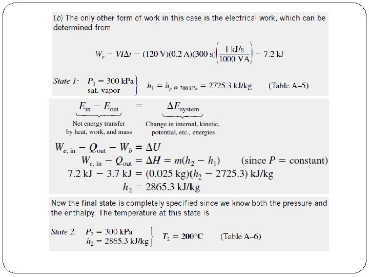
Example 2: Electric Heating of a Gas at Constant Pressure A piston-cylinder device contains 25 g of saturated water vapor that is maintained at a constant pressure of 300 k. Pa. A resistance heater within the cylinder is turned on and passes a current of 0. 2 A for 5 min from a 120 -V source. At the same time, a heat loss of 3. 7 k. J occurs. (a) Show that for a closed system the boundary work Wb and the change in internal energy U in the first-law relation can be combined into one term, H, for a constantpressure process. (b) Determine the final temperature of the steam.
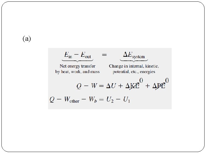

For a constant-pressure process, the boundary work is given as Wb=P 0(V 2 -V 1). Substituting this into the preceding relation gives Q-Wother- P 0(V 2 -V 1) =U 2 -U 1 However, P 0=P 2=P 1→Q-Wother=(U 2+P 2 V 2)-(U 1+P 1 V 1) Also H=U+PV, and thus Q-Wother=H 2 -H 1 (k. J) For a constant-pressure expansion or compression process:

ENERGY ANALYSIS OF STEADY-FLOW SYSTEMS Under steady-flow conditions, the mass and energy contents of a control volume remain constant. Many engineering systems such as power plants operate under steady conditions. 20 Under steady-flow conditions, the fluid properties at an inlet or exit remain constant (do not change with time).

Mass balances for a steady-flow process Mass balance A water heater in steady operation. Where; p is density, V is the average flow velocity in the flow direction. A is the cross-sectional area normal to the flow direction. 21

Energy balances for a steady-flow process Energy balance

Energy balance relations with sign conventions (i. e. , heat input and work output are positive) when kinetic and potential energy changes are negligible Some energy unit equivalents 23 Under steady operation, shaft work and electrical work are the only forms of work a simple compressible system may involve.

SOME STEADY-FLOW ENGINEERING DEVICES Many engineering devices operate essentially under the same conditions for long periods of time. The components of a steam power plant (turbines, compressors, heat exchangers, and pumps), for example, operate nonstop for months before the system is shut down for maintenance. Therefore, these devices can be conveniently analyzed as steady-flow devices. A modern land-based gas turbine used for electric power production. This is a General Electric LM 5000 turbine. It has a length of 6. 2 m, it weighs 12. 5 tons, and produces 55. 2 MW at 3600 rpm with steam injection. 24

Nozzles and Diffusers Nozzles and diffusers are commonly utilized in jet engines, rockets, spacecraft, and even garden hoses. A nozzle is a device that increases the velocity of a fluid at the expense of pressure. A diffuser is a device that increases the pressure of a fluid by slowing it down. The cross-sectional area of a nozzle decreases in the flow direction for subsonic flows and increases for supersonic flows. The reverse is true for diffusers. Nozzles and diffusers are shaped so that they cause large changes in fluid velocities and thus kinetic energies. 25 Energy balance for a nozzle or diffuser:

Turbines and Compressors Energy balance for the compressor in this figure: 26 • Turbine drives the electric generator In steam, gas, or hydroelectric power plants. • As the fluid passes through the turbine, work is done against the blades, which are attached to the shaft. As a result, the shaft rotates, and the turbine produces work. • Compressors, as well as pumps and fans, are devices used to increase the pressure of a fluid. Work is supplied to these devices from an external source through a rotating shaft. • A fan increases the pressure of a gas slightly and is mainly used to mobilize a gas. • A compressor is capable of compressing the gas to very high pressures. • Pumps work very much like compressors except that they handle liquids instead of gases.

Throttling valves are any kind of flow-restricting devices that cause a significant pressure drop in the fluid. What is the difference between a turbine and a throttling valve? The pressure drop in the fluid is often accompanied by a large drop in temperature, and for that reason throttling devices are commonly used in refrigeration and airconditioning applications. Energy balance 27 The temperature of an ideal gas does During a throttling process, the enthalpy of a fluid remains constant. But internal not change during a throttling (h = constant) process since h = h(T). and flow energies may be converted to each other.

Mixing chambers 60 C In engineering applications, the section where the mixing process takes place is commonly referred to as a mixing chamber. 140 k. Pa 10 C 43 C Energy balance for the adiabatic mixing chamber in the figure is: The T-elbow of an ordinary shower serves as the mixing chamber for the hot- and the cold-water streams. 28

Heat exchangers are devices where two moving fluid streams exchange heat without mixing. Heat exchangers are widely used in various industries, and they come in various designs. The heat transfer associated with a heat exchanger may be zero or nonzero depending on how the control volume is selected. Mass and energy balances for the adiabatic heat exchanger in the figure is: A heat exchanger can be as simple as 29 two concentric pipes.

Pipe and duct flow The transport of liquids or gases in pipes and ducts is of great importance in many engineering applications. Flow through a pipe or a duct usually satisfies the steady-flow conditions. Pipe or duct flow may involve more than one form of work at the same time. Heat losses from a hot fluid flowing through an uninsulated pipe or duct to the cooler environment may be very significant. 30 Energy balance for the pipe flow shown in the figure is

Thank You
- Slides: 31