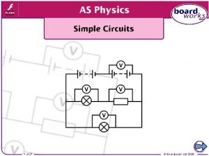
1 of 27 Boardworks Ltd 2009 2 of

1 of 27 © Boardworks Ltd 2009

2 of 27 © Boardworks Ltd 2009

Why use circuit symbols? When designing or recording results, scientists and engineers use diagrams to record their work in a simple, clear manner. Electrical circuits also require diagrams to record the relative position of different components. Circuit symbols are used, as they allow complex circuits to be drawn in a clear and precise manner, which is easily understood by anyone studying the image. 3 of 27 © Boardworks Ltd 2009

Basic circuit symbols 4 of 27 © Boardworks Ltd 2009

Specialized circuit components 5 of 27 © Boardworks Ltd 2009

6 of 27 © Boardworks Ltd 2009

Current is a measure of the amount of charge moving per second. I (A) = ΔQ (C) Δt (s) Electrons usually drift in a random direction, but there is no net movement of charge. When a potential difference is applied across a conductor a current is produced. This causes a net movement of charge in one direction, rather than a rapid flow. Electrons flow from a circuit’s negative terminal to positive terminal. However, traditionally current is drawn flowing in the opposite direction, and this is called conventional current. 7 of 27 © Boardworks Ltd 2009

Voltage, also known as potential difference, is a measure of the energy provided to the charge carriers. It can be defined as the amount of work done per unit charge. W (J) V (V) = Q (C) Voltage is measured as a difference in potential between two points. Thus a voltmeter must be connected in parallel and used to measure the difference in potential across a device. If a cell supplies 23 coulombs of charge with 776 J of energy, what is its voltage? 776 V= 23 8 of 27 = 33. 7 V © Boardworks Ltd 2009

Resistance is a measure of the opposition a material exerts against the flow of electrons. The resistance of a material can be calculated from the current and voltage passing through it. V (V) R (Ω) = I (A ) Calculate the resistance in this simple circuit. 9. 7 V 3. 2 A R= 9. 7 3. 2 = 3. 0 Ω Resistance can also be calculated from a V/I graph. 9 of 27 © Boardworks Ltd 2009

Investigating resistance 10 of 27 © Boardworks Ltd 2009

V I 5. 0 4. 5 0. 50 0. 45 4. 0 0. 40 3. 5 0. 35 3. 0 0. 30 2. 5 0. 25 2. 0 0. 20 1. 5 1. 0 0. 15 0. 10 voltage (V) Plotting the V/I graph for a resistor current (A) voltage 5 resistance = = gradient = = 10 Ω current 0. 5 As the graph is linear, R is constant. Therefore a resistor is an ohmic device. 11 of 27 © Boardworks Ltd 2009

V I 4. 5 4. 0 0. 415 3. 5 0. 410 3. 0 0. 400 2. 5 0. 370 2. 0 0. 330 1. 5 0. 270 1. 0 0. 5 0. 190 0. 090 voltage (V) Plotting the V/I graph for a bulb current (A) The graph is curved, therefore resistance is not constant. A bulb is a non-ohmic device. 12 of 27 © Boardworks Ltd 2009

The resistance of a non-ohmic device 13 of 27 © Boardworks Ltd 2009

Current, voltage and resistance summary 14 of 27 © Boardworks Ltd 2009

15 of 27 © Boardworks Ltd 2009

Kirchhoff’s first law The German physicist Gustav Kirchhoff established two laws which help us to understand the function of electric circuits. Kirchhoff’s first law states that: The sum of the currents leaving any junction is always equal to the sum of the currents that entered it. This law is based upon the idea of the conservation of charge: no charge can be lost or made in a circuit. I IN Thus the sum of the currents at a junction should be zero. IIN = I 1 + I 2 … + In ΣI = 0 16 of 27 I 1 I 3 I 2 © Boardworks Ltd 2009

Using Kirchhoff’s first law 17 of 27 © Boardworks Ltd 2009

The energy in a circuit What happens to the energy supplied to a circuit? Batteries and power supplies supply electrical energy to a circuit. Devices within the circuit transduce this energy: bulbs produce heat and light, resistors produce heat. What is the conservation of energy? Energy cannot be created or destroyed. All of the energy provided by a power supply must be used by the circuit. How does the voltage of a battery relate to the voltage measured across the devices in a circuit? Voltage is the energy transferred to the charge in a circuit. The battery’s voltage is shared between the components, which transduce this energy into different forms. 18 of 27 © Boardworks Ltd 2009

Kirchhoff’s second law is based upon the law of the conservation of energy. It states that: The total voltage across a circuit loop is equal to the sum of the voltage drops across the devices in that loop. Essentially, the energy you put into the circuit equals the energy you get out of each circuit loop. An equation can be produced for each loop in a circuit. For example: VIN = V 1 + V 2 VIN = IR 1 + IR 2 19 of 27 VIN I V 1 V 2 R 1 R 2 © Boardworks Ltd 2009

Simple uses of Kirchhoff’s second law 20 of 27 © Boardworks Ltd 2009

Further uses for Kirchhoff’s law Use Kirchhoff’s laws to find the values for each current. E = 12 V V 1 10 Ω V 2 100 Ω V 3 40 Ω As I = I 1 I 2 I 3 V R I = 1. 6 A 21 of 27 l There are 3 loops in the circuit. Each has a voltage drop equal to the input voltage according to the 2 nd law. I Therefore: E = V 1 = V 2 = V 3 l The 1 st law means that current entering each junction equals the current leaving. Therefore: I = I 1 + I 2 + I 3 I = 12 + 12 10 100 40 I 1 = 1. 2 A I = 1. 2 + 0. 12 + 0. 3 I 2 = 0. 1 A I 3 = 0. 3 A © Boardworks Ltd 2009

Using Kirchhoff’s laws 22 of 27 © Boardworks Ltd 2009

Summary: Kirchhoff’s laws 23 of 27 © Boardworks Ltd 2009

24 of 27 © Boardworks Ltd 2009

Glossary 25 of 27 © Boardworks Ltd 2009

What’s the keyword? 26 of 27 © Boardworks Ltd 2009

Multiple-choice quiz 27 of 27 © Boardworks Ltd 2009
- Slides: 27
