
1 Lecture 2 Hydraulic Pump 2 1 Basic

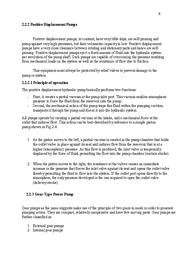
1 Lecture 2 -Hydraulic / Pump 2. 1 Basic Hydraulic Systems Regardless of its function and design, every hydraulic system has a minimum number of basic components in addition to a means through which the fluid is transmitted. A basic system consists of (as in fig. 2. 1): 1. Pump 2. Reservoir, 3. Directional valve 4. Check valve 5. Pressure relieve valve 6. Selector valve 7. Actuator 8. Filter. Figure 2. 1: Basic hydraulic system. 2. 2 Pump The function of a pump is to convert mechanical energy into hydraulic energy. It is the heart of any hydraulic system because it generates the force necessary to move the load. Mechanical energy is delivered to the pump using a prime mover such as an electric motor. The hydraulic pump takes hydraulic fluid (mostly some oil) from the storage tank and delivers it to the rest of the hydraulic circuit. Pumps can be broadly listed under two categories:
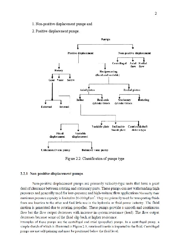
2 1. Non-positive displacement pumps and 2. Positive displacement pumps. Figure 2. 2: Classification of pumps type
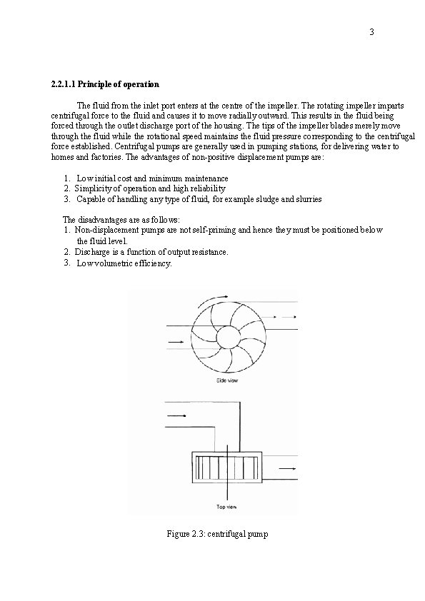
3 2. 2. 1. 1 Principle of operation The fluid from the inlet port enters at the centre of the impeller. The rotating impeller imparts centrifugal force to the fluid and causes it to move radially outward. This results in the fluid being forced through the outlet discharge port of the housing. The tips of the impeller blades merely move through the fluid while the rotational speed maintains the fluid pressure corresponding to the centrifugal force established. Centrifugal pumps are generally used in pumping stations, for delivering water to homes and factories. The advantages of non-positive displacement pumps are: 1. Low initial cost and minimum maintenance 2. Simplicity of operation and high reliability 3. Capable of handling any type of fluid, for example sludge and slurries The disadvantages are as follows: 1. Non-displacement pumps are not self-priming and hence they must be positioned below the fluid level. 2. Discharge is a function of output resistance. 3. Low volumetric efficiency. Figure 2. 3: centrifugal pump
4 2. 2. 2 Positive Displacement Pumps Positive displacement pumps, in contrast, have very little slips, are self-priming and pump against very high pressures, but their volumetric capacity is low. Positive displacement pumps have a very close clearance between rotating and stationary parts and hence are selfpriming. Positive displacement pumps eject a fixed amount of fluid into the hydraulic system per revolution of the pump shaft. Such pumps are capable of overcoming the pressure resulting from mechanical loads on the system as well as the resistance of flow due to friction. This equipment must always be protected by relief valves to prevent damage to the pump or system 2. 2. 2. 1 Principle of operation The positive displacement hydraulic pump basically performs two functions: - First, it creates a partial vacuum at the pump inlet port. This vacuum enables atmospheric pressure to force the fluid from the reservoir into the pump. Second, the mechanical action of the pump traps this fluid within the pumping cavities, transports it through the pump and forces it into the hydraulic system. All pumps operate by creating a partial vacuum at the intake, and a mechanical force at the outlet that induces flow. This action can be best described by reference to a simple piston pump shown in Fig. 2. 4. 1. As the piston moves to the left, a partial vacuum is created in the pump chamber that holds the outlet valve in place against its seat and induces flow from the reservoir that is at a higher (atmospheric) pressure. As this flow is produced, the inlet valve is temporarily displaced by the force of fluid, permitting the flow into the pump chamber (suction stroke). 2. When the piston moves to the right, the resistance at the valves causes an immediate increase in the pressure that forces the inlet valve against its seat and opens the outlet valve thereby permitting the fluid to flow into the system. If the outlet port opens directly to the atmosphere, the only pressure developed is the one required to open the outlet valve (delivery stroke). 2. 2. 3 Gear-Type Power Pump Gear pumps as the name suggests make use of the principle of two gears in mesh in order to generate pumping action. They are compact, relatively inexpensive and have few moving parts. Gear pumps are further classified as: 1. External gear pumps 2. Internal gear pumps
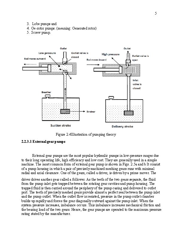
5 3. Lobe pumps and 4. Ge-rotor pumps. (meaning: Generated rotor) 5. Screw pump. Figure 2. 4 Illustration of pumping theory 2. 2. 3. 1 External gear pumps are the most popular hydraulic pumps in low-pressure ranges due to their long operating life, high efficiency and low cost. They are generally used in a simple machine. The most common form of external gear pump is shown in Figs. 2. 5 a and b It consist of a pump housing in which a pair of precisely machined meshing gears runs with minimal radial and axial clearance. One of the gears, called a driver, is driven by a prime mover. The driver drives another gear called a follower. As the teeth of the two gears separate, the fluid from the pump inlet gets trapped between the rotating gear cavities and pump housing. The trapped fluid is then carried around the periphery of the pump casing and delivered to outlet port. The teeth of precisely meshed gears provide almost a perfect seal between the pump inlet and the pump outlet. When the outlet flow is resisted, pressure in the pump outlet chamber builds up rapidly and forces the gear diagonally outward against the pump inlet. When the system pressure increases, imbalance occurs. This imbalance increases mechanical friction and the bearing load of the two gears. Hence, the gear pumps are operated to the maximum pressure rating stated by the manufacturer.
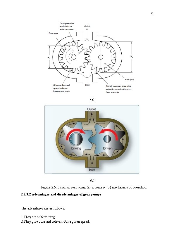
6 (a) (b) Figure 2. 5: External gear pump (a) schematic (b) mechanism of operation 2. 2. 3. 2 Advantages and disadvantages of gear pumps The advantages are as follows: 1. They are self-priming. 2. They give constant delivery for a given speed.
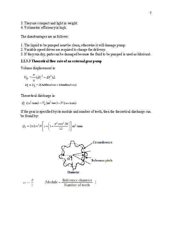
7 3. They are compact and light in weight. 4. Volumetric efficiency is high. The disadvantages are as follows: 1. The liquid to be pumped must be clean, otherwise it will damage pump. 2. Variable speed drives are required to change the delivery. 3. If they run dry, parts can be damaged because the fluid to be pumped is used as lubricant. 2. 2. 3. 3 Theoretical flow rate of an external gear pump Volume displacement is: Theoretical discharge is: If the gear is specified by its module and number of teeth, then theoretical discharge can be found by:
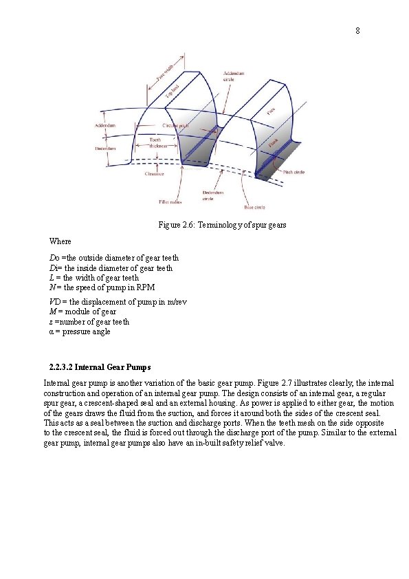
8 Figure 2. 6: Terminology of spur gears Where Do =the outside diameter of gear teeth Di= the inside diameter of gear teeth L = the width of gear teeth N = the speed of pump in RPM VD = the displacement of pump in m/rev M = module of gear z =number of gear teeth α = pressure angle 2. 2. 3. 2 Internal Gear Pumps Internal gear pump is another variation of the basic gear pump. Figure 2. 7 illustrates clearly, the internal construction and operation of an internal gear pump. The design consists of an internal gear, a regular spur gear, a crescent-shaped seal and an external housing. As power is applied to either gear, the motion of the gears draws the fluid from the suction, and forces it around both the sides of the crescent seal. This acts as a seal between the suction and discharge ports. When the teeth mesh on the side opposite to the crescent seal, the fluid is forced out through the discharge port of the pump. Similar to the external gear pump, internal gear pumps also have an in-built safety relief valve.

9 Figure 2. 7 Schematic diagram of internal gear pump operation 2. 2. 3. 3 Lobe pump The lobe pump is yet another variation of the basic gear pump. This pump operates in a fashion quite similar to that of an external gear pump, but unlike external gear pumps, the gears in these pumps are replaced with lobes which usually consist of three teeth. Figure 2. 8 shows the operation of a lobe pump. Unlike the external gear pumps, both the lobes are driven externally so that they do not actually make contact with each other. They are quieter than the other gear pumps. Due to the smaller number of mating elements, the lobe pump will show a greater amount of pulsation. However, its volumetric displacement is generally greater than other types of gear pumps. Although these pumps have a low-pressure rating, they are well-suited for applications involving shear-sensitive fluids. Figure 2. 8 Schematic diagram of Lobe pump operation 2. 2. 3. 4 Gerotor pump The gerotor internal-gear pump consists of a pair of gears which are always in sliding contact. The internal gear has one more tooth than the gerotor gear. Both gears rotate in the

10 same direction as in fig. 2. 9. Oil is drawn into the chamber where the teeth are separating, and is ejected when the teeth start to mesh again. The seal is provided by the sliding contact. Figure 2. 8 Schematic diagram of Gerotor pump operation Example 2. 1: The inlet to a hydraulic pump is 0. 6 m below the top surface of an oil reservoir. If the specific gravity of the oil used is 0. 86, determine the static pressure at the pump inlet. Example 2. 2: A hydraulic pump delivers 12 L of fluid per minute against a pressure of 200 bar. (a) Calculate the hydraulic power. (b) If the overall pump efficiency is 60%, what size of electric motor would be needed to drive the pump?
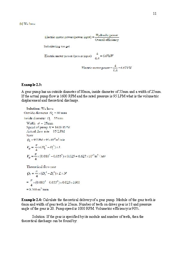
11 Example 2. 3: A gear pump has an outside diameter of 80 mm, inside diameter of 55 mm and a width of 25 mm. If the actual pump flow is 1600 RPM and the rated pressure is 95 LPM what is the volumetric displacement and theoretical discharge. Example 2. 4: Calculate theoretical delivery of a gear pump. Module of the gear teeth is 6 mm and width of gear teeth is 25 mm. Number of teeth on driver gear is 18 and pressure angle of the gear is 20. Pump speed is 1000 RPM. Volumetric efficiency is 90%. Solution: If the gear is specified by its module and number of teeth, then theoretical discharge can be found by:
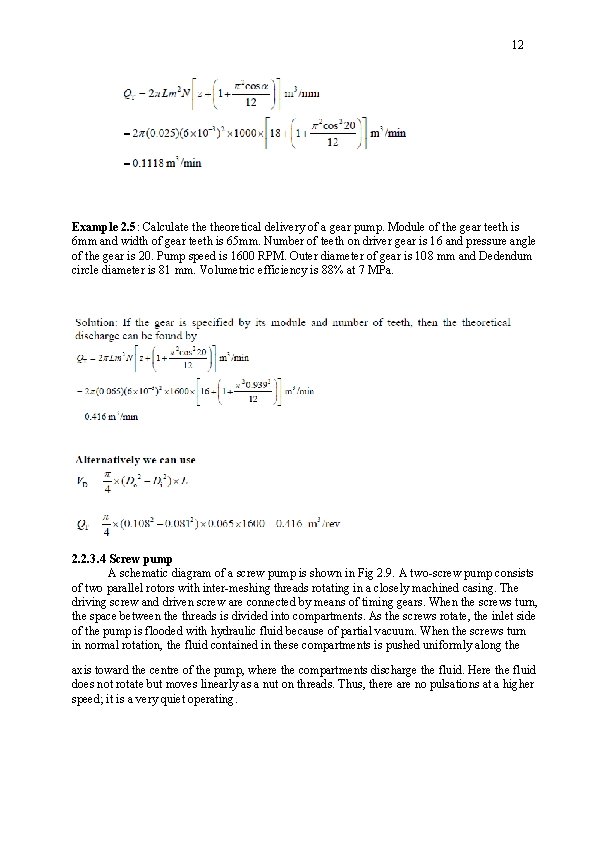
12 Example 2. 5: Calculate theoretical delivery of a gear pump. Module of the gear teeth is 6 mm and width of gear teeth is 65 mm. Number of teeth on driver gear is 16 and pressure angle of the gear is 20. Pump speed is 1600 RPM. Outer diameter of gear is 108 mm and Dedendum circle diameter is 81 mm. Volumetric efficiency is 88% at 7 MPa. 2. 2. 3. 4 Screw pump A schematic diagram of a screw pump is shown in Fig 2. 9. A two-screw pump consists of two parallel rotors with inter-meshing threads rotating in a closely machined casing. The driving screw and driven screw are connected by means of timing gears. When the screws turn, the space between the threads is divided into compartments. As the screws rotate, the inlet side of the pump is flooded with hydraulic fluid because of partial vacuum. When the screws turn in normal rotation, the fluid contained in these compartments is pushed uniformly along the axis toward the centre of the pump, where the compartments discharge the fluid. Here the fluid does not rotate but moves linearly as a nut on threads. Thus, there are no pulsations at a higher speed; it is a very quiet operating.
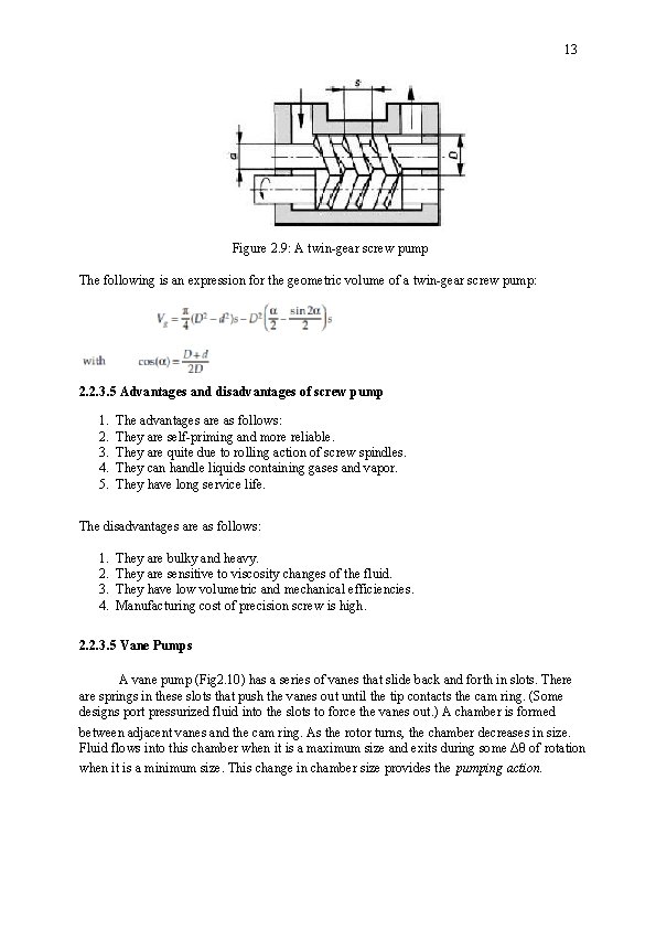
13 Figure 2. 9: A twin-gear screw pump The following is an expression for the geometric volume of a twin-gear screw pump: 2. 2. 3. 5 Advantages and disadvantages of screw pump 1. 2. 3. 4. 5. The advantages are as follows: They are self-priming and more reliable. They are quite due to rolling action of screw spindles. They can handle liquids containing gases and vapor. They have long service life. The disadvantages are as follows: 1. 2. 3. 4. They are bulky and heavy. They are sensitive to viscosity changes of the fluid. They have low volumetric and mechanical efficiencies. Manufacturing cost of precision screw is high. 2. 2. 3. 5 Vane Pumps A vane pump (Fig 2. 10) has a series of vanes that slide back and forth in slots. There are springs in these slots that push the vanes out until the tip contacts the cam ring. (Some designs port pressurized fluid into the slots to force the vanes out. ) A chamber is formed between adjacent vanes and the cam ring. As the rotor turns, the chamber decreases in size. Fluid flows into this chamber when it is a maximum size and exits during some Δθ of rotation when it is a minimum size. This change in chamber size provides the pumping action.

14 Figure 2. 10 Schematic diagram of Unbalanced vane pump Schematic diagram of variable displacement vane pump is shown in Fig. 2. 11. Variable displacement feature can be brought into vane pumps by varying eccentricity between the rotor and the cam ring. Here in this pump, the stator ring is held against a spring loaded piston. The system pressure acts directly through a hydraulic piston on the right side. This forces the cam ring against a spring-loaded piston on the left side. If the discharge pressure is large enough, it overcomes the compensated spring force and shifts the cam ring to the left. Figure 2. 11: Operation of a variable displacement vane pump The advantages of vane pumps are as follows: 1. Vane pumps are self-priming, robust and supply constant delivery at a given speed. 2. They provide uniform discharge with negligible pulsations. 3. Their vanes are self-compensating for wear and vanes can be replaced easily. 4. These pumps do not require check valves. 5. They are light in weight and compact.

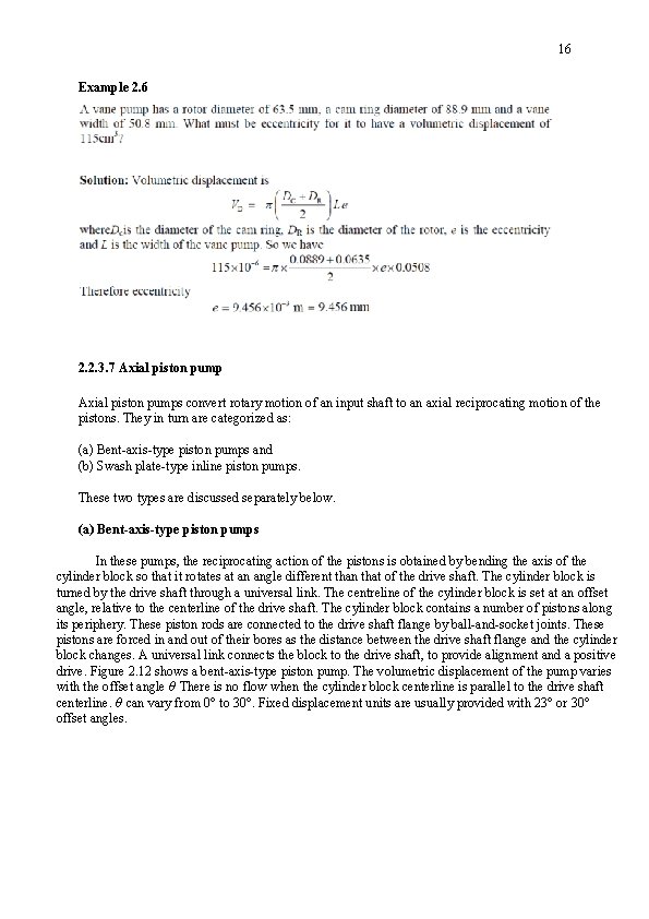
16 Example 2. 6 2. 2. 3. 7 Axial piston pumps convert rotary motion of an input shaft to an axial reciprocating motion of the pistons. They in turn are categorized as: (a) Bent-axis-type piston pumps and (b) Swash plate-type inline piston pumps. These two types are discussed separately below. (a) Bent-axis-type piston pumps In these pumps, the reciprocating action of the pistons is obtained by bending the axis of the cylinder block so that it rotates at an angle different than that of the drive shaft. The cylinder block is turned by the drive shaft through a universal link. The centreline of the cylinder block is set at an offset angle, relative to the centerline of the drive shaft. The cylinder block contains a number of pistons along its periphery. These piston rods are connected to the drive shaft flange by ball-and-socket joints. These pistons are forced in and out of their bores as the distance between the drive shaft flange and the cylinder block changes. A universal link connects the block to the drive shaft, to provide alignment and a positive drive. Figure 2. 12 shows a bent-axis-type piston pump. The volumetric displacement of the pump varies with the offset angle θ There is no flow when the cylinder block centerline is parallel to the drive shaft centerline. θ can vary from 0° to 30°. Fixed displacement units are usually provided with 23° or 30° offset angles.
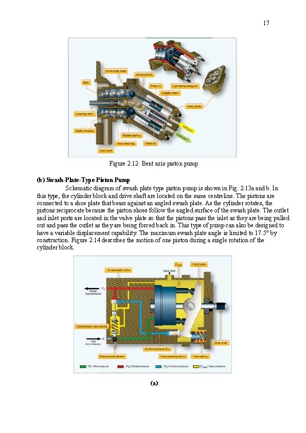
17 Figure 2. 12: Bent axis piston pump (b) Swash-Plate-Type Piston Pump Schematic diagram of swash plate type piston pump is shown in Fig. 2. 13 a and b. In this type, the cylinder block and drive shaft are located on the same centreline. The pistons are connected to a shoe plate that bears against an angled swash plate. As the cylinder rotates, the pistons reciprocate because the piston shoes follow the angled surface of the swash plate. The outlet and inlet ports are located in the valve plate so that the pistons pass the inlet as they are being pulled out and pass the outlet as they are being forced back in. This type of pump can also be designed to have a variable displacement capability. The maximum swash plate angle is limited to 17. 5° by construction. Figure 2. 14 describes the motion of one piston during a single rotation of the cylinder block. (a)
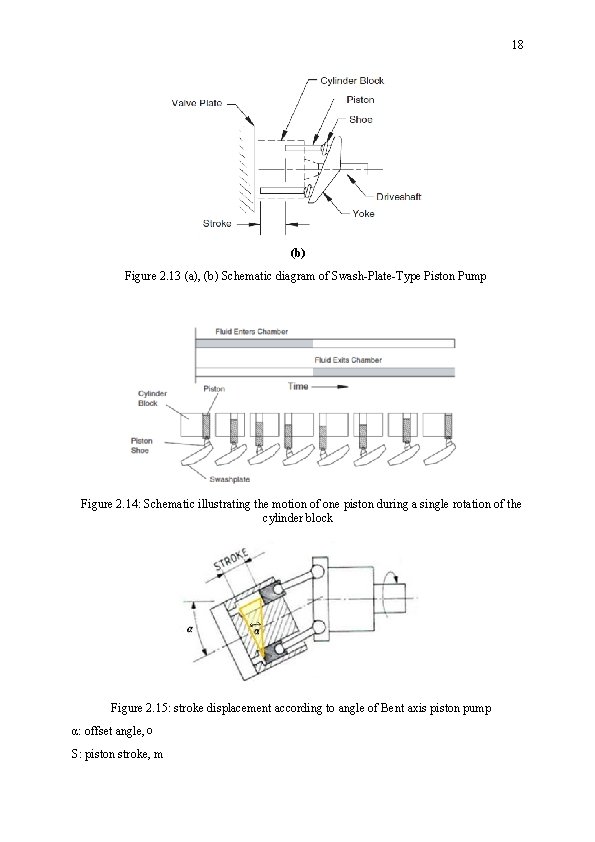
18 (b) Figure 2. 13 (a), (b) Schematic diagram of Swash-Plate-Type Piston Pump Figure 2. 14: Schematic illustrating the motion of one piston during a single rotation of the cylinder block Figure 2. 15: stroke displacement according to angle of Bent axis piston pump α: offset angle, o S: piston stroke, m


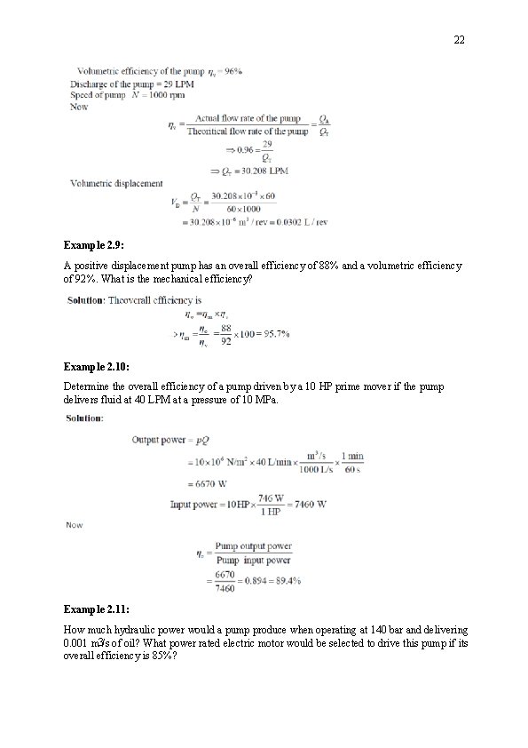
22 Example 2. 9: A positive displacement pump has an overall efficiency of 88% and a volumetric efficiency of 92%. What is the mechanical efficiency? Example 2. 10: Determine the overall efficiency of a pump driven by a 10 HP prime mover if the pump delivers fluid at 40 LPM at a pressure of 10 MPa. Example 2. 11: How much hydraulic power would a pump produce when operating at 140 bar and delivering 0. 001 m 3/s of oil? What power rated electric motor would be selected to drive this pump if its overall efficiency is 85%?
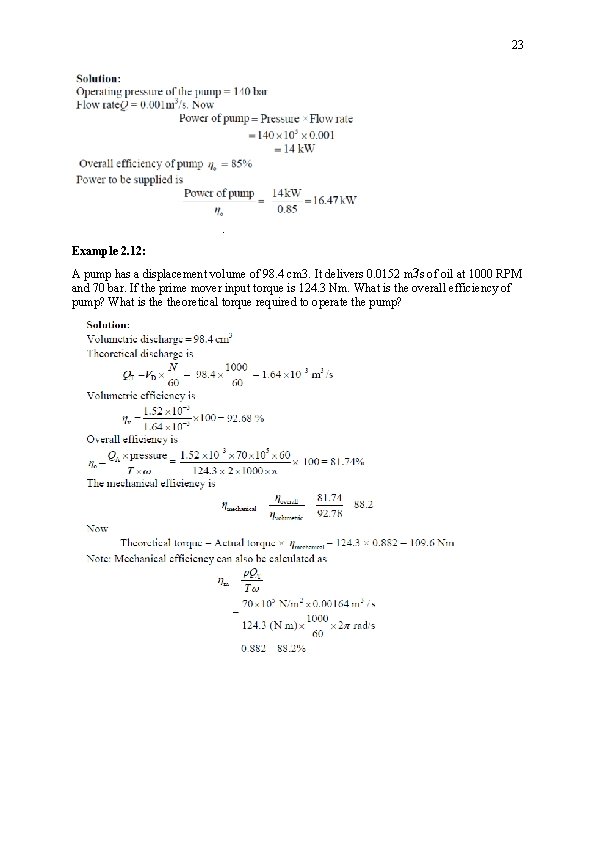
23 . Example 2. 12: A pump has a displacement volume of 98. 4 cm 3. It delivers 0. 0152 m 3/s of oil at 1000 RPM and 70 bar. If the prime mover input torque is 124. 3 Nm. What is the overall efficiency of pump? What is theoretical torque required to operate the pump?
- Slides: 23