1 June 2017 EDM BRAINSTORM KICKOFF Polarized proton

1 June 2017 EDM BRAINSTORM

KICKOFF

Polarized proton beam preparation for injection into the EDM storage ring at CERN • • • Gianluigi Arduini Alessandra Lombardi Christian Carli Jacques Lettry Themis Bowcock Anatoli Zelenski Meeting after kick-off • Full energy 232. 8 Me. V longitudinally polarized proton injection into the EDM storage ring p = 0. 7 Ge. V/c, v/c = 0. 6, KE = 233 Me. V
 BNL")
Source? • Characteristics – current, pulse duration, emittance • • Ion type (s) BNL re-use? Ballpark cost for transfer or construction Infrastructure requirements

Accelerator chain options 2 x 10¹¹ p/pulse Polarized P source 2 x 10¹¹ Polarized H- source Linac-2 50 Me. V LEIR 1 x 10¹¹ p/pulse 232. 8 Me. V EDM storage ring 11 p/pulse 1 x 10 160 Me. V 232. 8 Me. V Linac-4 Booster EDM storage ring H-/pulse Vertical polarization direction adjusted in the LEBT and maintained vertical along the accelerator chain and HEBT lines. Aligned to longitudinal just before injection into the storage ring.

Options + - Linac 2 -LEIR Dedicated linac Electron cooling Age of Linac 2 Linac 3 -LEIR Extant Electron cooling Two sources Competition with ions Linac 4 -PBS Extant Heavy competition No electron cooling Two sources for Linac 4++ H- to full energy Cost, real estate, switching Two sources for Linac 4 Green field Linac to 233 Me. V Designed for purpose Cost New linac in Linac 2 tunnel Dedicated linac Electron cooling Nice new linac Cost

Courtesy Ed Stephenson
 polarimeter, protons for")
Common • • Polarized ion source produces atomic beam for (Breit-Rabi) polarimeter, protons for beam line. Pulse is a few hundred micro-seconds long. At ke. V energies, electric field rotates proton beam without changing polarization direction. Rotate polarization into vertical direction so that it will survive LEIR. Linac provides energy (50 Me. V) for LEIR injection. After acceleration, check polarization by scattering from carbon or deuterium. Send into LEIR, electron cool for a tight bunch. Raise energy to 232. 8 Me. V. This involves crossing the Gγ=2 imperfection resonance, which should be done quickly. We should check for other machine resonances. Polarimeter after LEIR confirms that polarization has survived. This uses carbon scattering and can be the calibration measurement for the polarization. Consider thicker target with holes (50% transmitting) for “flash” calibration in single integrated pulse. Courtesy Ed Stephenson

Vertical injection into EDM ring • Bending magnet connects to both CW and CCW injection on separate fills. • Beams must be in tight bunches, or else the rotation into the horizontal plane will leave behind residual parts of the beam with unacceptably large normal components. Harmonic = 2. • RF solenoid runs at beam revolution frequency and is matched so that peak of oscillating field matches time of bunch crossing through solenoid. • Two bunches for each beam will have opposite polarization. Then each must be split to get higher harmonic for experiment with mixing with opposite polarization. Courtesy Ed Stephenson

Horizontal injection into EDM ring • Solenoid rotates polarization into horizontal plane. Fine adjustment cancels vertical components in EDM ring. • CW and CCW must be done with polarizations in the same direction, otherwise we cannot later align the two beams for frozen spin condition separately. Maintaining the same direction also sets up CCW as the time reversed experiment. • Bunch structure in EDM ring is arbitrary. Polarization cannot be reversed on single fill, so opposite polarization state requires separate fill. Courtesy Ed Stephenson

Injection of longitudinally polarized proton beam Vertically polarized 232. 8 Me. V proton beam SC solenoid rotate vertical Polarization to horizontal P ๏ 50. 2 deg. bending magnet rotate transverse polarization to longitudinal

Symmetrical beam injection Vertically polarized 232. 8 Me. V proton beam P ๏ 50. 2 deg. bending magnet rotate transverse polarization to longitudinal ๏ ๏ SC solenoid rotate vertical Polarization to horizontal Second, counter -propagating beam
 of the")
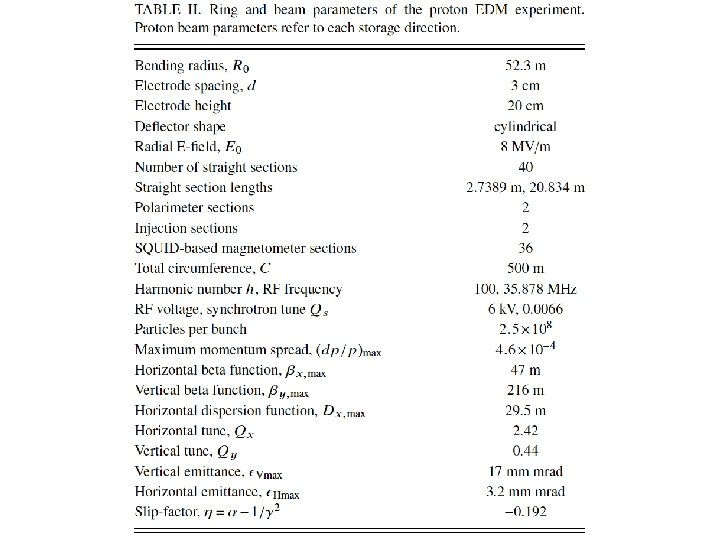
Ring – basic requirements • Given the timescale (5 – 10 years) of the experiment we do not need sophisticated ancillary buildings • There is no radiation hazard from this beam so shielding can be minimal • Consider cut-and-fill as well as pure on-surface solutions. • The vibration isolation and the temperature control are modest and the degree to which these need to be done depends largely on cost. For example the similar g-2 experiment at BNL operated with +/- 10 ˚ C. • The cross-section of the storage ring including shielding is approx. 1 m 2 – does not need huge power supplies or cryogenics. Cryo-cool but do not need super conducting magnets – access needs to be on 2 or 3 “sides” of the storage ring.

Circumference c/o Yannis, Themis 250 m 440 m 940 m

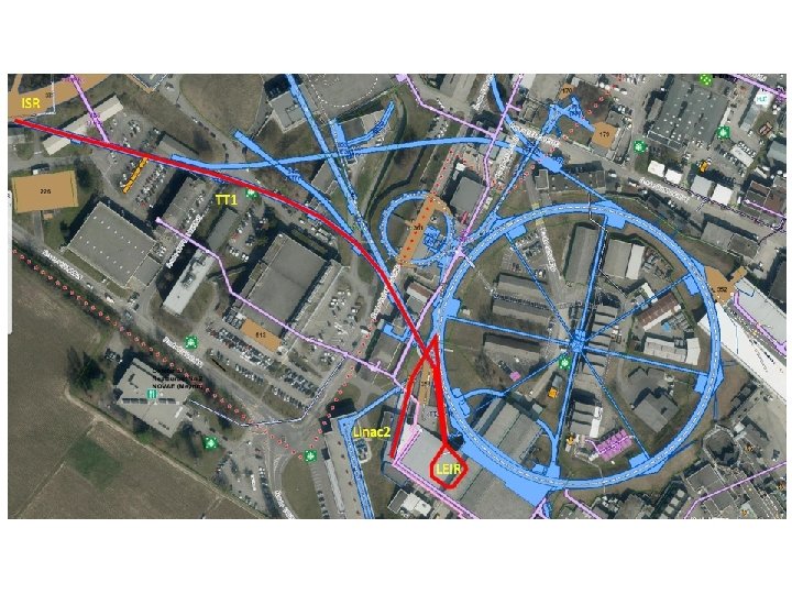
Site? • “green” field in middle of the ISR real estate – Worry about existing infrastructure – But transfer lines to ISR in place • Use existing ring – ISR, PS? – ISR - longer running time, full (!) of mildly radioactive waste • Green field site (Prevessin, say) • Any other brown-field sites at CERN?

160 m
 – Tunnel cross-section, volumes –")
CE Requirements • Need input (possibly from BNL study) – Tunnel cross-section, volumes – Required stability – Services (CV, EL, CRYO …) – Shielding (RP, EL…) – Access, safety • The best way to get the process going is to start doing some layout drawings – it looks a bit tricky though in the ISR area with all the existing technical galleries • Preliminary civil engineering study: ~50 k. CHF approved • John Osborne has asked member of CE draughting team (Raul) to have a look

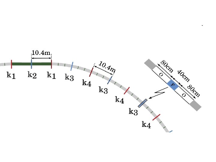
Bends + SSS 10. 471 m 40 416. 68 m LSS 20. 834 m 4 83. 336 m Total 500. 016 m • 8 MV/m • SQUIDS and electrostatic quadrupoles in SSS • Two polarimeters in LSS

How real could we get? Could we come up with a ball-park cost?
")
Electrostatic deflectors Electrostatic deflector development ongoing at RWTH Aachen (electrode materials, surface treatments…)

What’s the question for us? Could we assume the technology is mastered and ask how much would 40 2. 5 m exquisitely engineered deflectors and associated infrastructure cost What would the installation look like (HV supplies, cables etc. )? Plus quads!

Systems 1/2 Given the layout, will need to run through… requirements, sketch implementation, estimate cost… System Group Proposed contact Source ABP Jacques Lettry Acceleration ABP Christian Carli Transfer line ABP Christian Carli Injection layout ABP Christian Carli Injection system ABT Jan Borburgh? Deflectors ABT Jan Borburgh Power supplies EPC RF RF Olivier Brunner Steffen Doebert Beam instrumentation including magnetometers BI Rhodri Jones/Ray Veness Vacuum VSC Ray? Magnetic shielding Off-site for input?

Systems 2/2 System Group Contact Cryogenics CRG Cooling and ventilation CV Electrical systems EL Survey SU Integration ACE Beam intercepting devices STI Not at this stage Controls CO Not at this stage Interlocks MPE Not at this stage Radiation protection/safety HSE Not at this stage? Transport HE Not at this stage

The CSR consists of an experimental vacuum system kept below 10 K by integrated pumping units working at 2 K. Two radiation shields at 40 and 80 K house the experimental vacuum chambers. An outer vacuum system acting as a cryostat provides an insulation vacuum of 10 -6 mbar. The purely electrostatic storage ring with a circumference of 35 m is composed of four 90 o-bending corners and four field free straight sections for beam diagnostics and experimental setups.
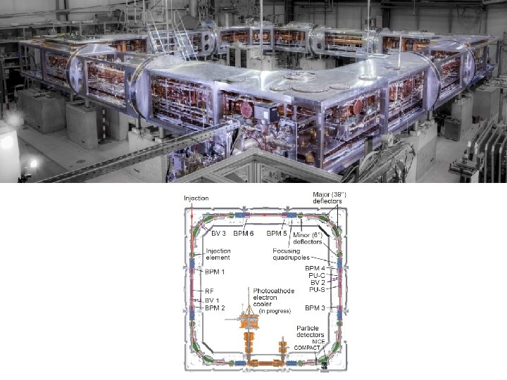

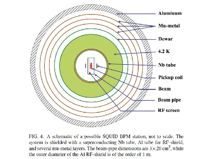
Figure 2: Photograph of electrostatic quadrupole at Heidelberg and the magnetic shielding. The cross-section is approx. 1 m 2 as proposed for p. EDM,

What next? • CE – Drawings, sketch space requirements, services… • Source, beam delivery, injection – Develop options – Explore transfer options to ISR site ring (input to CE) • Key technology – go and pick brains – what’s out there… – – – Shielding Electrostatic deflectors Beam instrumentation (BPMs, SQUIDS. . . ) • Other systems – establish hard requirements. . – RF, vacuum. .
- Slides: 31