
1 Graduation project Project Residential building 3 Introduction

1
Graduation project Project Residential building 3

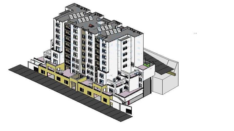
Introduction ü Rawabi building is residential building a located in Rawabi city; it consists of eight floors , with total area of 2850 m 2. Structural elements will be designed as reinforced concrete members according to strength and serviceability criteria as specified in ACI 318, for seismic design UBC-97 code will be used.
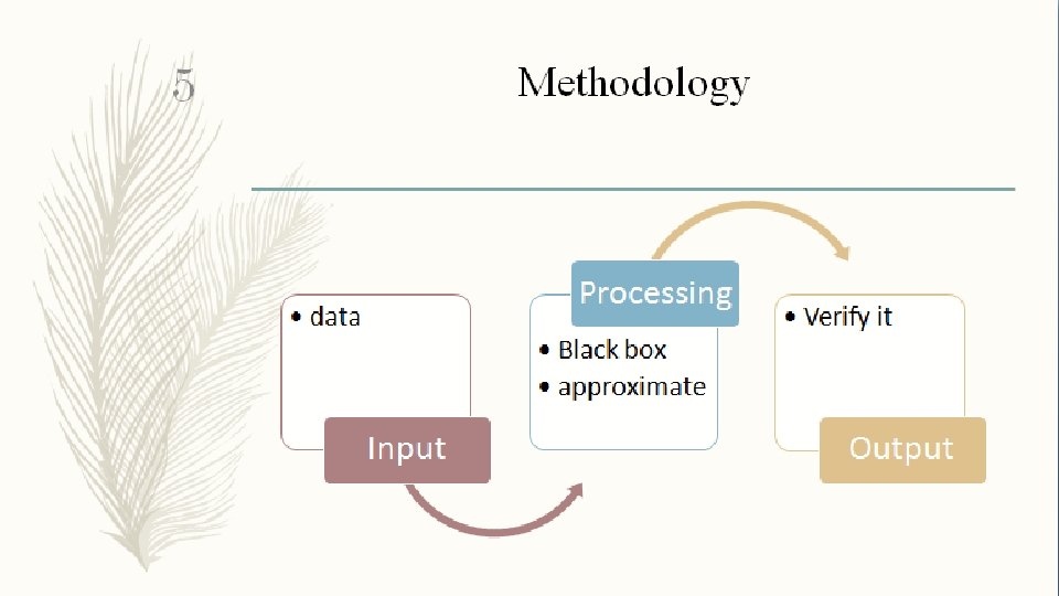
Methodology Processing • data • Black box • approximate Input 5 • Verify it Output
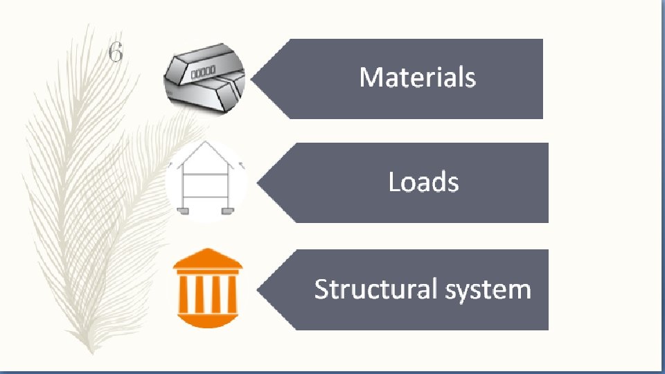
Materials Loads Structural system 6
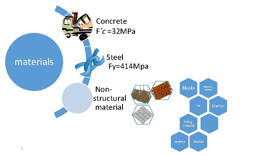
Concrete F’c =32 MPa materials Steel Fy=414 Mpa Nonstructural material Blocks masonry stones Tile Filling material insulation 7 Marble Mortar
Soil properties • From the report soil the foundation of building is rock - rock is the common foundation in Rawabi - and the allowable bearing capacity for rock is 400 k. N/m 2. 8
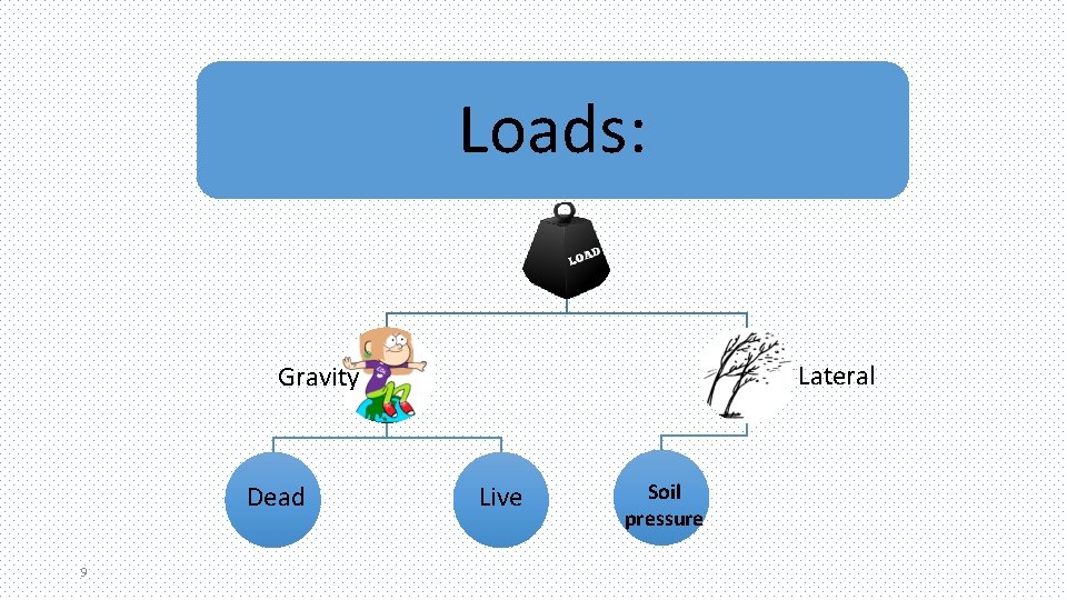
Loads: Lateral Gravity Dead 9 Live Soil pressure
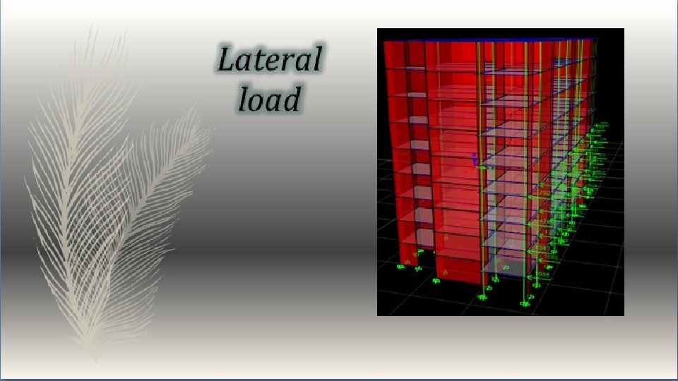
Lateral load
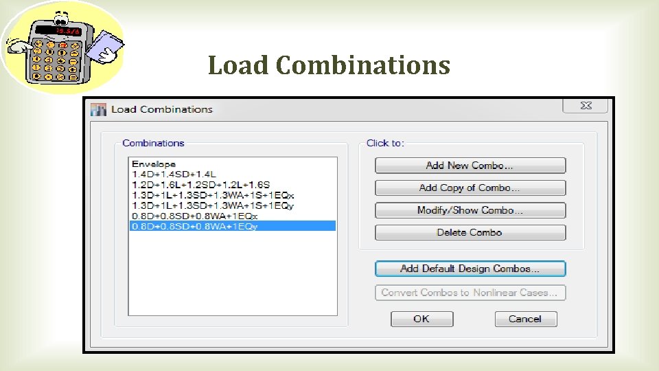
Load Combinations

Design Criteria Strength and safe Economy Serviceability

Structural System
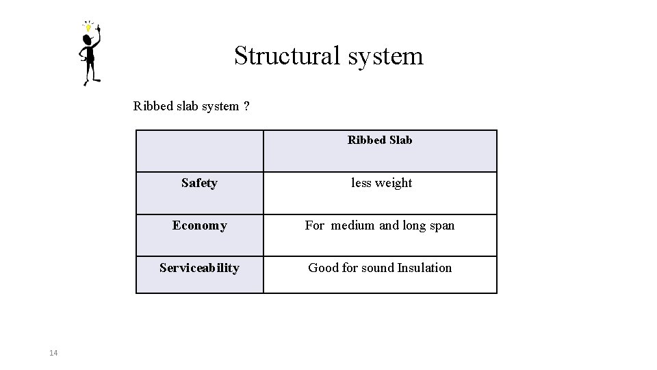
Structural system Ribbed slab system ? Ribbed Slab 14 Safety less weight Economy For medium and long span Serviceability Good for sound Insulation
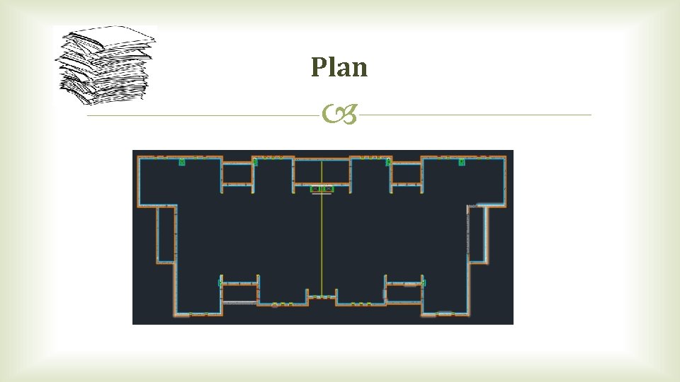
Plan
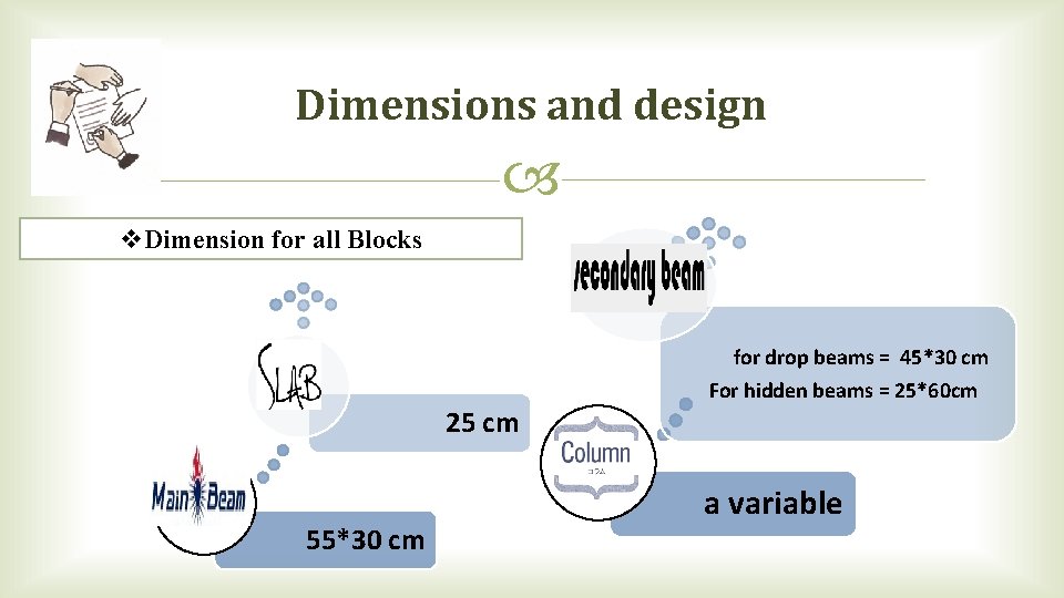
Dimensions and design v. Dimension for all Blocks for drop beams = 45*30 cm For hidden beams = 25*60 cm 25 cm 55*30 cm a variable
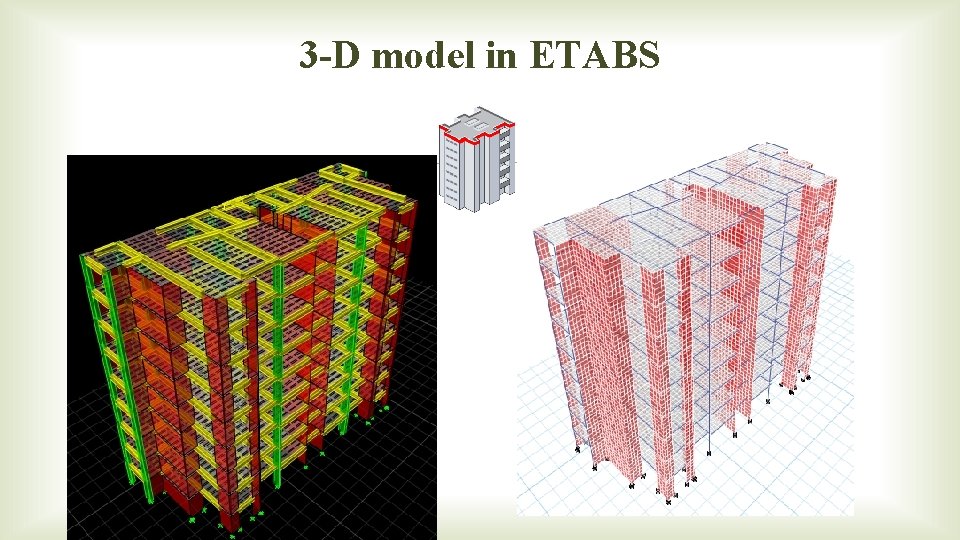
3 -D model in ETABS
Modifiers Just as a reminder: q Crack modifiers. q Fake modifiers.
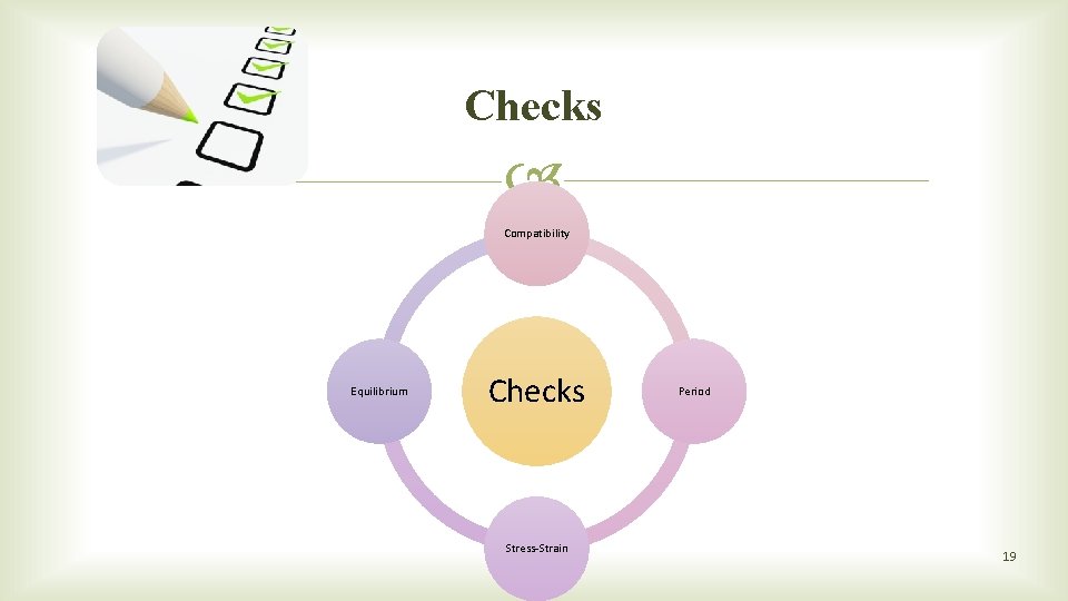
Checks Compatibility Equilibrium Checks Stress-Strain Period 19

Seismic Design Structure period ü check period by using Method A formula: T = Ct*H 3/4 Where: Ct = 0. 0731 for moment resistant concrete frames T = 0. 0731* (25. 2) ¾ T=0. 82 sec
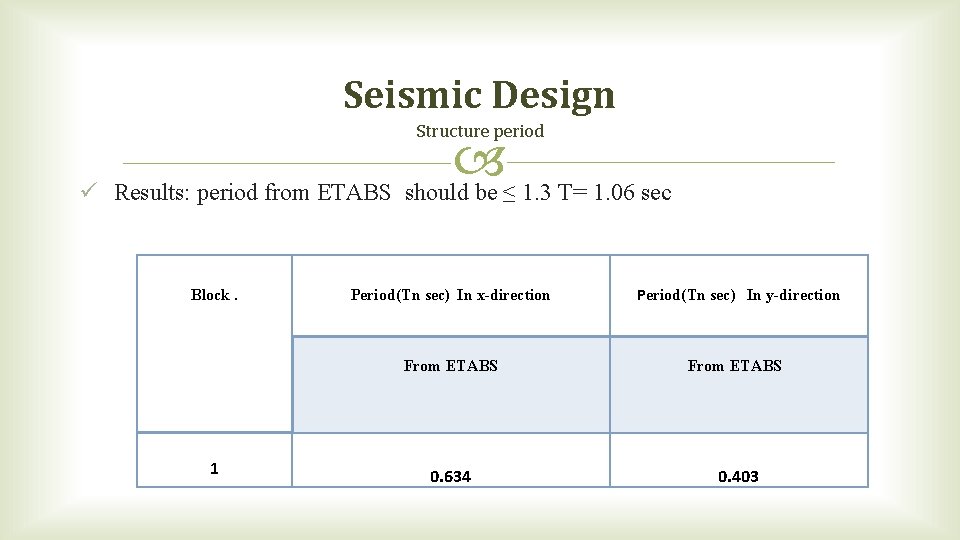
Seismic Design Structure period ü Results: period from ETABS should be ≤ 1. 3 T= 1. 06 sec Block. 1 Period(Tn sec) In x-direction Period(Tn sec) In y-direction From ETABS 0. 634 0. 403
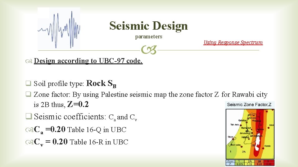
Seismic Design parameters Using Response Spectrum Design according to UBC-97 code. q Soil profile type: Rock SB q Zone factor: By using Palestine seismic map the zone factor Z for Rawabi city is 2 B thus, Z=0. 2 q Seismic coefficients: Ca and Cv Ca =0. 20 Table 16 -Q in UBC Cv = 0. 20 Table 16 -R in UBC
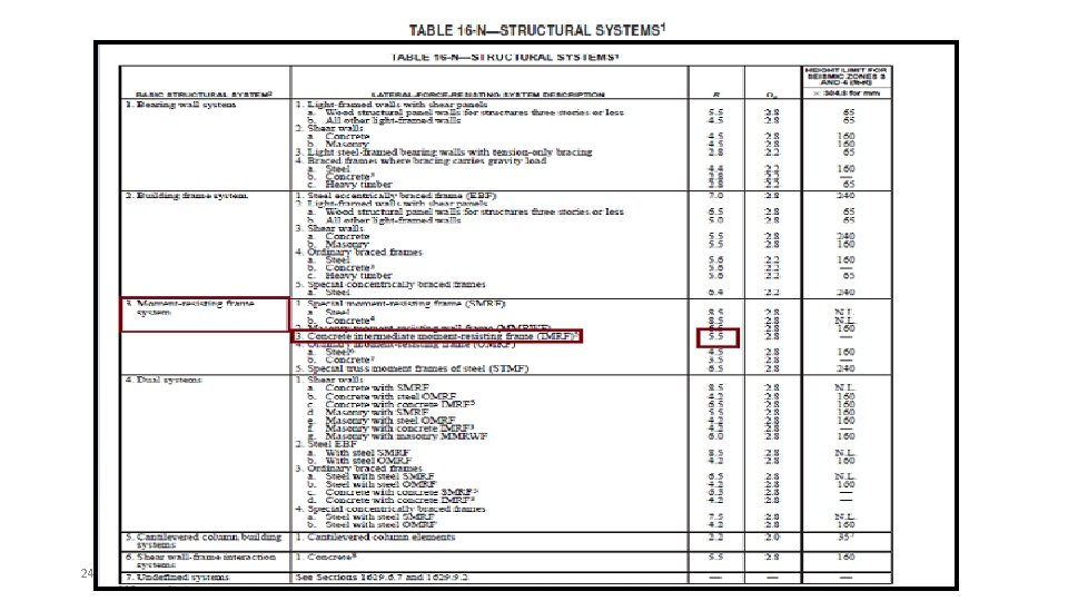
24
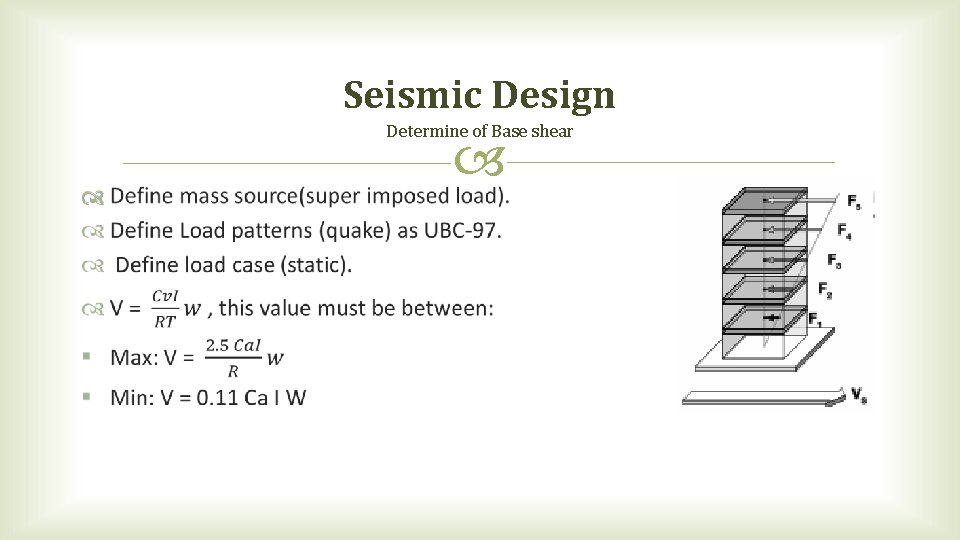
Seismic Design Determine of Base shear
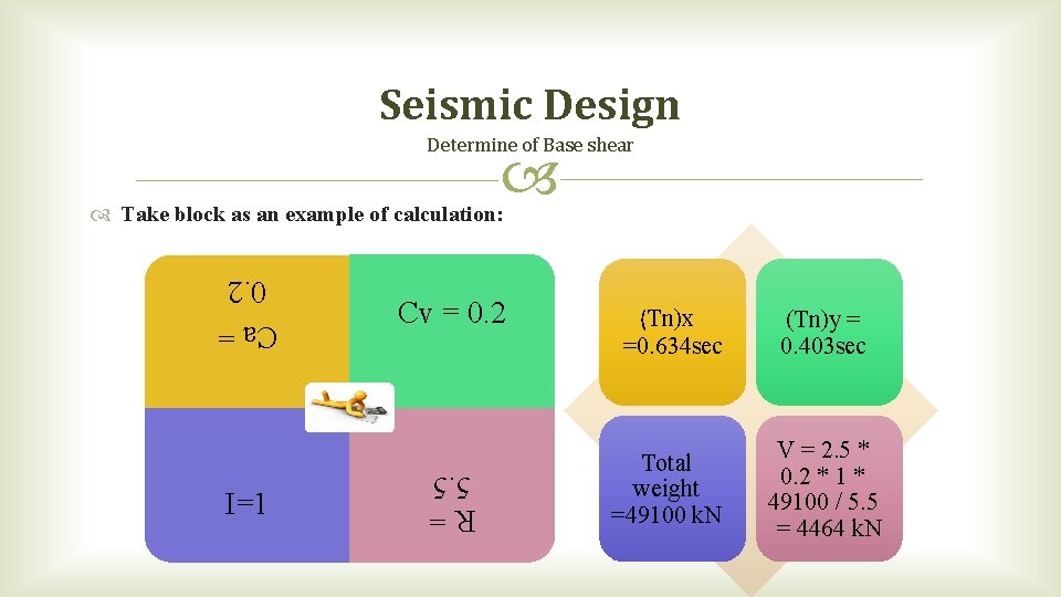
Seismic Design Determine of Base shear Take block as an example of calculation: R= 5. 5 Ca = 0. 2 I=1 Cv = 0. 2 (Tn)x =0. 634 sec (Tn)y = 0. 403 sec Total weight =49100 k. N V = 2. 5 * 0. 2 * 1 * 49100 / 5. 5 = 4464 k. N
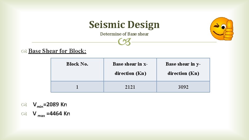
Seismic Design Determine of Base shear Base Shear for Block: Block No. 1 Vmin=2089 Kn V max =4464 Kn Base shear in x- Base shear in y- direction (Kn) 2121 3092
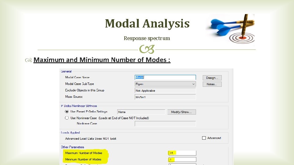
Modal Analysis Response spectrum Maximum and Minimum Number of Modes :

Modal Analysis Response Spectrum Mass Participation Ratio:
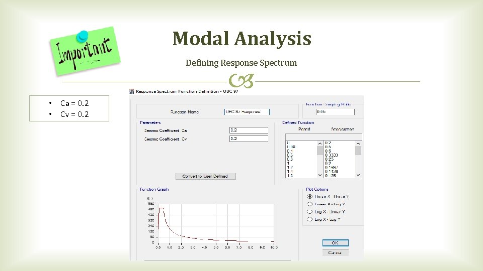
Modal Analysis Defining Response Spectrum • Ca = 0. 2 • Cv = 0. 2
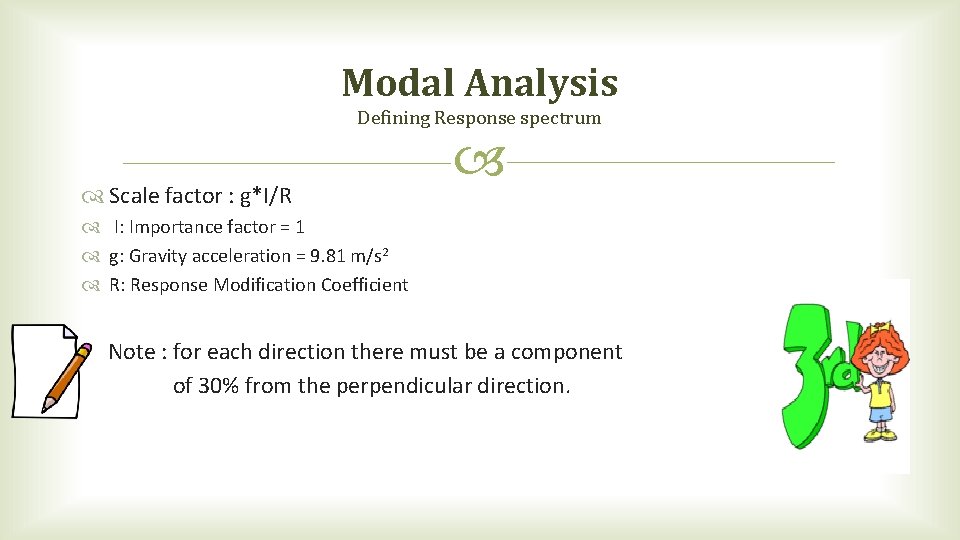
Modal Analysis Defining Response spectrum Scale factor : g*I/R I: Importance factor = 1 g: Gravity acceleration = 9. 81 m/s 2 R: Response Modification Coefficient Note : for each direction there must be a component of 30% from the perpendicular direction.

Modal Analysis Defining Response spectrum response spectrum in x-direction
Modal Analysis Base shear from Response spectrum Base shear from response differ than that in equivalent static. As a requirement from UBC-97 : response spectrum base shear is (85 - 100) percent of the base shear determined in equivalent static method. so, modify scale factor: scale factor = ((I g / R) * static base shear / response-spectrum base shear)
Modal Analysis Base shear from Response spectrum Base shear in x-direction Base shear in y-direction (k. N) Block. From static From Scale VES response factor static response factor VRS VES / VES VRS VES / VRS 1 2089 2121 1. 7 VRS 2089 3091 1. 2
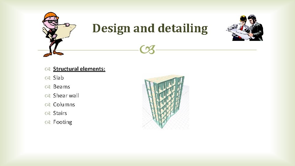
Design and detailing Structural elements: Slab Beams Shear wall Columns Stairs Footing
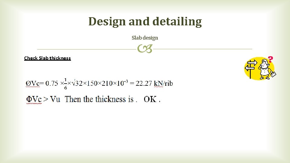
Design and detailing Slab design Check Slab thickness
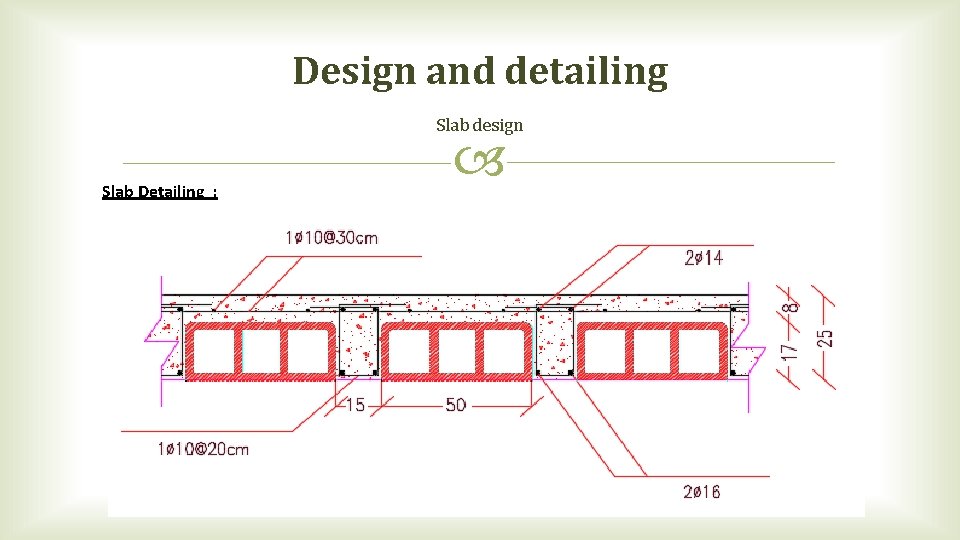
Design and detailing Slab design Slab Detailing :
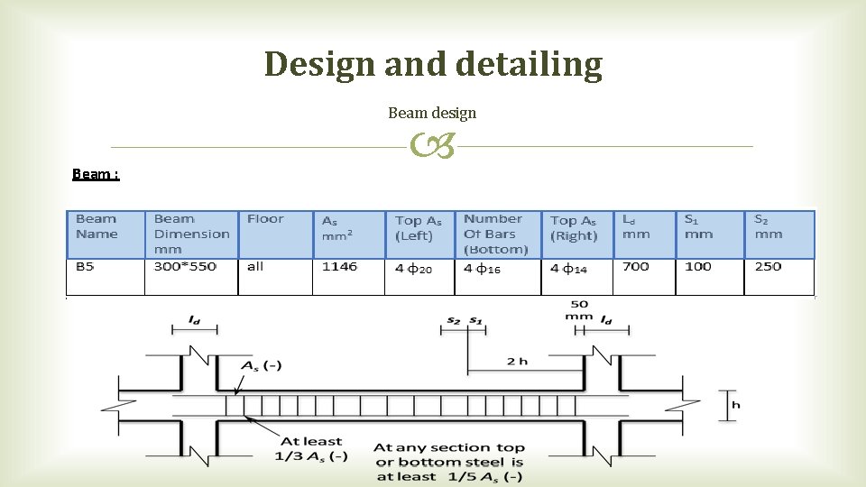
Design and detailing Beam design Beam :
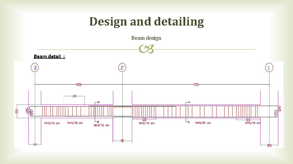
Design and detailing Beam design Beam detail :
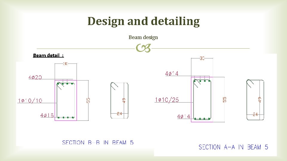
Design and detailing Beam design Beam detail :
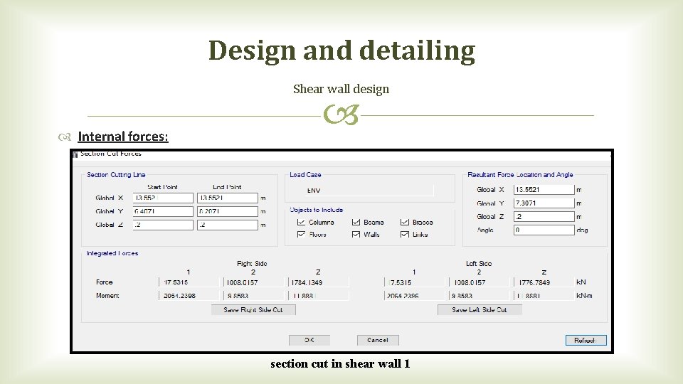
Design and detailing Shear wall design Internal forces: section cut in shear wall 1
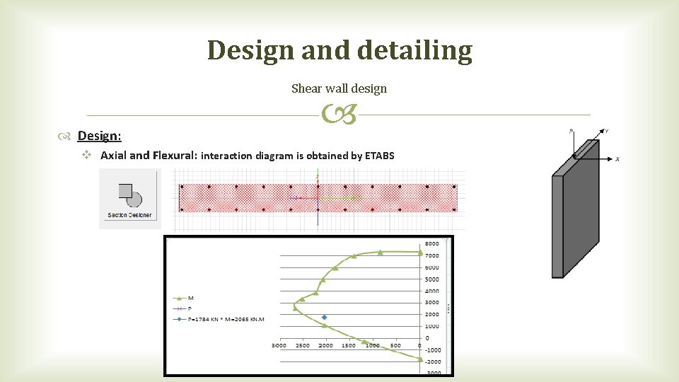
Design and detailing Shear wall design Design: v Axial and Flexural: interaction diagram is obtained by ETABS
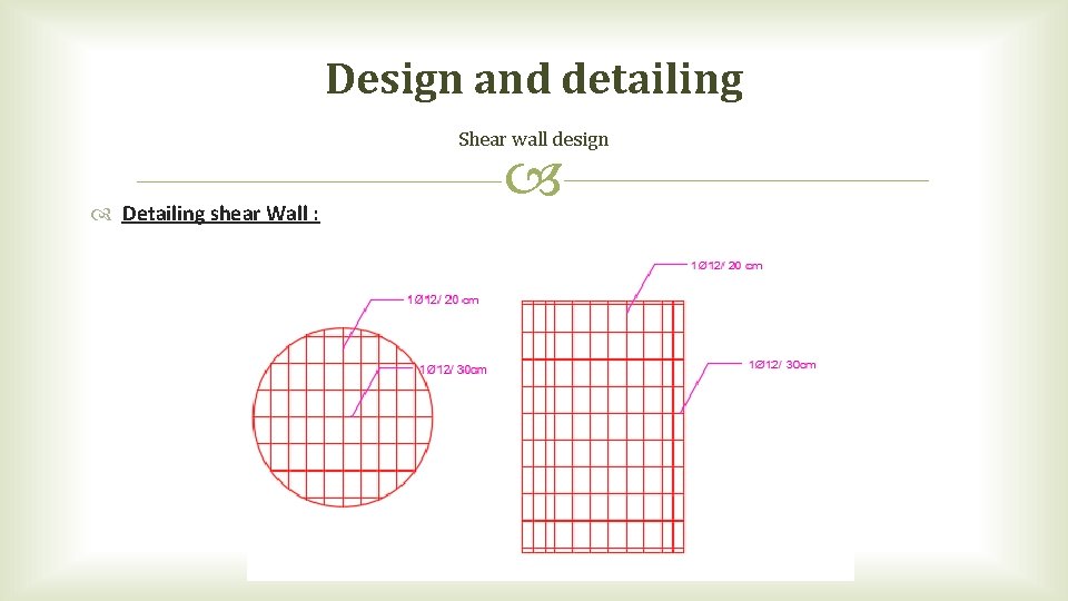
Design and detailing Shear wall design Detailing shear Wall :
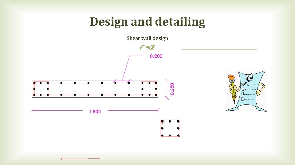
Design and detailing Shear wall design
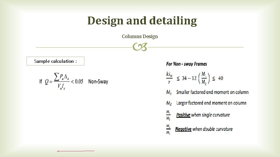
Design and detailing Columns Design Sample calculation :
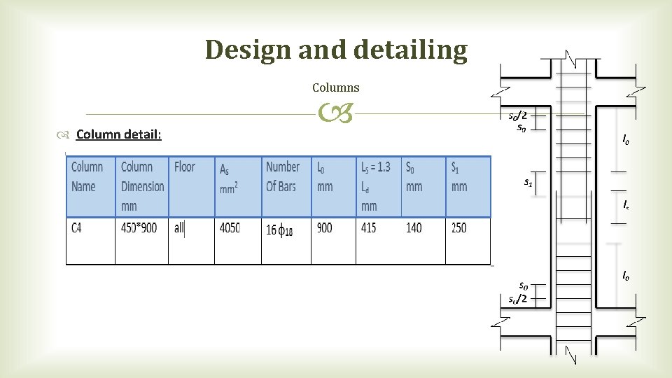
Design and detailing Columns Column detail:
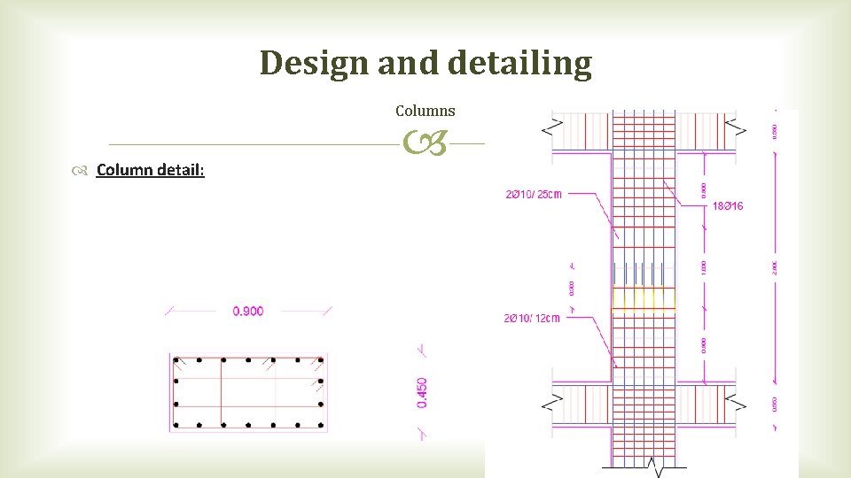
Design and detailing Columns Column detail:
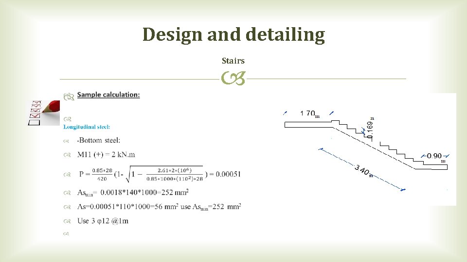
Design and detailing Stairs
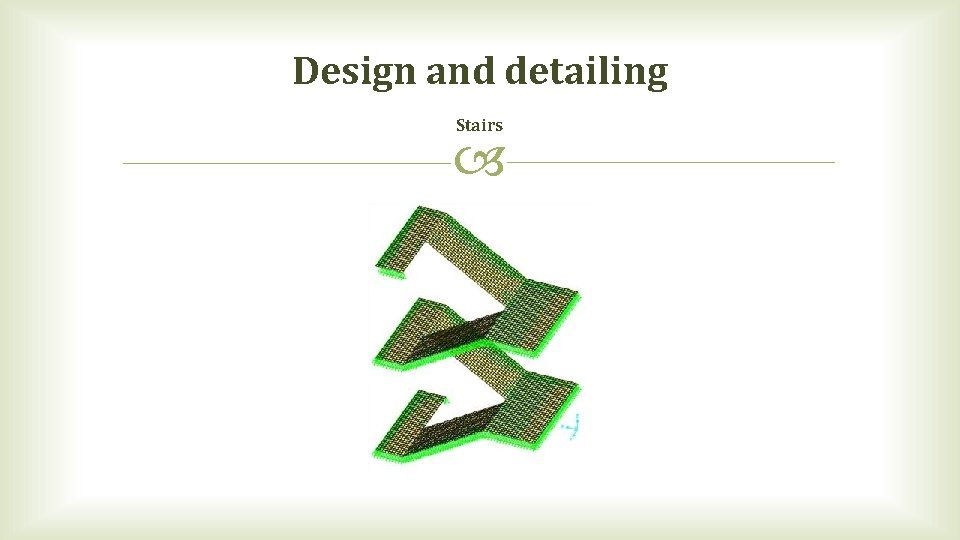
Design and detailing Stairs
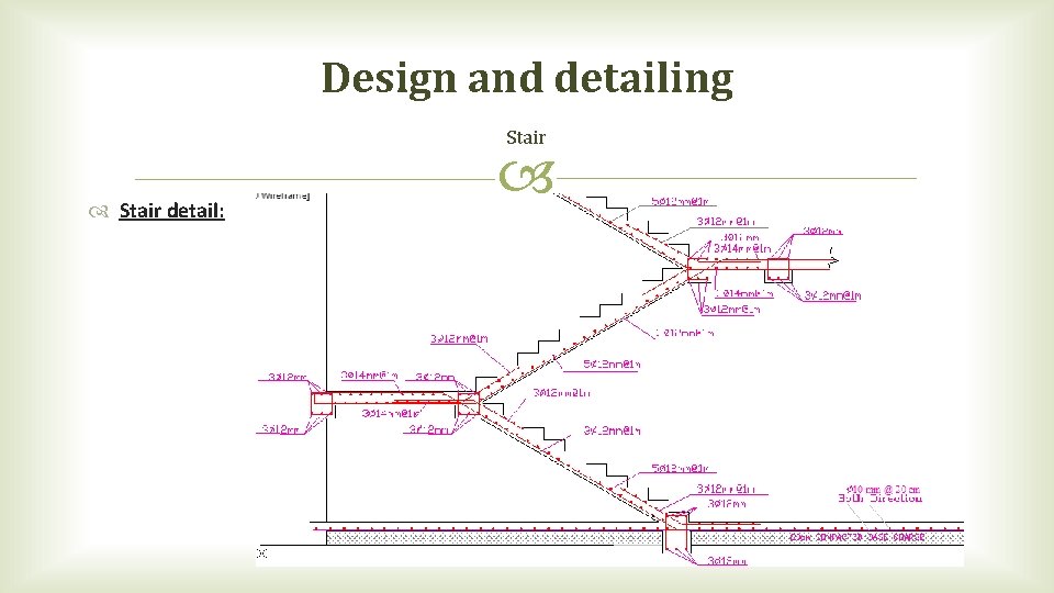
Design and detailing Stair detail:

51
- Slides: 50