1 Directional couplers EMLAB 7 4 Waveguide directional

1 Directional couplers EMLAB

7. 4 Waveguide directional coupler 2 Waveguide two-hole coupler Isolated Input Coupled Through EMLAB
 Two commonly used symbols for directional couplers, and")
3 Figure 7. 4 (p. 313) Two commonly used symbols for directional couplers, and power flow conventions. EMLAB

Application : network analyzer 4 S-Parameter Test Set Source Transfer switch Directional coupler R B A Port 2 Port 1 Fwd DUT Rev EMLAB

Waveguide multi-hole coupler 5 EMLAB

7. 5 Quadrature hybrid coupler ① ④ 6 ② ③ EMLAB

7 Even-odd mode analysis ① ① ② ② ④ ④ ③ ③ Line of symmetry I=0 V=max ① ④ ② ③ Line of anti-symmetry I = max V=0 EMLAB

8 EMLAB

9 EMLAB

10 Even mode analysis ① ④ Line of symmetry I=0 V=max ② ③ ① ② ④ ③ Open circuited stubs EMLAB

11 ① ② EMLAB

12 Odd mode analysis Line of anti-symmetry I=max V=0 Short-circuited stubs GND via EMLAB

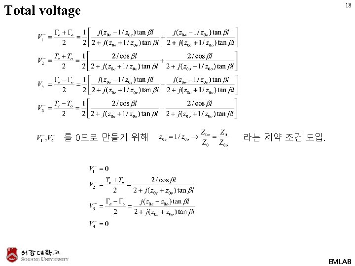
13 ① ② Total scattered voltage EMLAB

14 7. 6 Coupled line coupler Microstrip coupler Coaxial coupler EMLAB

Even-odd mode analysis 15 EMLAB

Even mode analysis 16 EMLAB

Odd mode analysis 17 EMLAB

Design of couple line coupler 19 Isolated Coupled EMLAB

Freq. response of couple line coupler 20 EMLAB

21 7. 8 180° hybrid coupler 180° phase difference Sum, difference EMLAB
 Even- and odd-mode")
7. 8 180° hybrid coupler 22 Figure 7. 44 (p. 354) Even- and odd-mode decomposition of the ring hybrid when port 1 is excited with a unit amplitude incident wave. (a) Even mode. (b) Odd mode. EMLAB

Even mode analysis 23 EMLAB

Odd mode analysis 24 EMLAB
 Even- and odd-mode decomposition of the ring hybrid")
25 Figure 7. 45 (p. 356) Even- and odd-mode decomposition of the ring hybrid when port 4 is excited with a unit amplitude incident wave. (a) Even mode. (b) Odd mode. EMLAB

Ring hybrid modulator 26 EMLAB

27 EMLAB
- Slides: 27